
Synthetic liquid fuel production from gasification
J.G. Speight CD&W Inc., Laramie, WY, USA
Abstract
Gasification can be used to convert a variety of feedstock substrates (tar sand bitumen, coal, oil shale, and biomass are used as the examples) to distillate products. This chapter provides a general description of the Fischer-Tropsch technology and the production and upgrading of synthetic crude oil. In addition, recent developments in thermal technology for synthetic fuel production are also presented. Also, for comparison, the chapter provides presentation of the means by which non–Fischer-Tropsch synthetic crude oil is converted to specification-grade fuels.
7.1 Introduction
The varying prices of crude oil, the politics of crude oil, and other variable economic factors have led to a strong interest in the production of liquid fuels from coal, natural gas, and biomass (Hu, Yu, & Lu, 2012; Speight, 2008, 2011a, 2011b). The technology to produce fuels from such sources is varied, but a tried and true technology involves the so-called indirect process in which the feedstock is first converted to gases (particularly synthesis gas) from which liquid products are generated by the Fischer-Tropsch (FT) process (Kreutz, Larson, Liu, & Williams, 2008).
Current conditions almost reprise the era of the 1970s when energy security concerns generated by oil embargoes stimulated federal spending in synthetic fuels. Despite considerable investment, federal support in many countries was withdrawn after supply concerns eased in the 1980s. The currently favored approach to producing synthetic fuels – the Fischer-Tropsch process – used synthesis gas (mixtures of carbon monoxide and hydrogen from the gasification of carbonaceous materials (fossil fuels or organically derived feedstocks) (Gary, Handwerk, & Kaiser, 2007; Hsu & Robinson, 2006; Speight, 2008, 2013a, 2013b, 2014; Speight & Ozum, 2002).
Many countries have attempted to capitalize on the gasification-with-Fischer-Tropsch method but the up-and-down prices of petroleum – especially when petroleum process are lower – tend to discourage such efforts on the basis of poor economic return. Nevertheless, several private ventures in the United States and throughout the world are now studying the feasibility of constructing FT synthetic fuel plants based on petroleum residue, coal, natural gas, and biomass. It is required that governments make the decision to support such efforts rather than react at a time when the occasion has passed and fuel shortages are endemic. Perhaps this is too much to ask – that a government will use foresight instead of hindsight, which is always 20-20.
The Fischer-Tropsch process is well suited to producing naphtha, which is the precursor to gasoline, as well as middle-distillate range fuels such as diesel fuel and jet fuel. The diesel produced is superior to conventionally refined diesel in terms of higher cetane number and low sulfur content. Overall, middle distillate fuels represent roughly a quarter of many refinery operations, which are typically driven by the demand for gasoline. In order for a synthetic fuels industry (whether coal, natural gas, or biomass based) to begin rivaling or even supplanting conventional petroleum refining, a major shift in political outlook would have to occur.
In addition, recent energy legislation promotes research on capturing and storing greenhouse gas emissions and improving vehicle fuel efficiency, among other goals. Fisher-Tropsch fuels present the paradox of high-carbon emissions associated with production versus lower-carbon emissions associated with their use.
Hence, as crude oil production decreases and its price increases, the Fischer-Tropsch technology, which enables the production of synthetic hydrocarbons from carbonaceous feedstocks, is becoming an increasingly attractive technology in the energy mix. In fact, coupled with this is the fact that FT products are ultra-clean fuels in that they contain no aromatics, no sulfur compounds, and no nitrogen compounds. In essence, compared to petroleum-derived gasoline and diesel fuel, the analogous product produced by the Fischer-Tropsch process will burn to produce considerably less polynuclear aromatic hydrocarbons (PNAs), and no sulfur oxides (SOx) and no nitrogen oxides (NOx). With global pressures to reduce greenhouse gas emissions intensifying, legislative frameworks in Europe and the United States have already been put in place to force producers of liquid transportation fuels to comply with stricter emission standards. The impact of such legislation is that dilution of petroleum-derived fuels with the cleaner FT-derived fuels is becoming an increasingly important way to achieve environmental compliance. Thus, it is not surprising that FT technology now occupies a visible place in the energy mix required for sustainable global development.
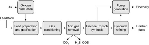
This section will provide the reader with a broad perspective of thermal decompositon pyrolysis technology as it relates to converting a variety of feedstocks substrates (tar sand bitumen, coal, oil shale, and biomass are used as the examples) to distillate products for the reader to compare with gasification technologies and Fischer-Tropsch technologies that are the focus of this book. Thus, this chapter provides a general description of the FT technology and the production and upgrading of synthetic crude oil (Figure 7.1). In addition, recent developments in thermal technology for synthetic fuel production are also presented and, for comparison, the chapter also provides presentation of the means by which non–Fischer-Tropsch synthetic crude oil is converted to specification-grade fuels.
7.2 Fischer-Tropsch synthesis
The Fischer-Tropsch process is well known and has been commercially demonstrated internationally and in pilot plant demonstration in many countries (Chadeesingh, 2011). As an abundant resource in many non-oil–producing countries, coal has long been exploited as a solid fossil fuel. As oil and natural gas supplanted coal throughout the last two centuries, technologies developed to convert coal into other fuels. Proponents of expanding the use of the FT process argue that the United States and many other countries could alleviate its dependence on imported petroleum and strained refinery capacity by converting non-petroleum feedstocks to transportation fuels.
Fischer-Tropsch synthesis, particularly the coal-based process, poses several challenges: (1) the process is criticized as inefficient and costly; (2) carbon dioxide – a greenhouse gas associated with global climate change – is a by-product of the process; (3) the use of coal and natural gas as Fischer-Tropsch feedstocks would compete with electric power generation; (4) the fuels produced, primarily diesel fuel and jet fuel, would not substitute widely for the preferred transportation fuel – gasoline; and (5) the use of biomass as feedstock would compete with cellulosic ethanol production, as it is now envisioned. Each of these items is part reality and part mythology that can be overcome by judicious planning to silence (if that is possible) the nay-sayers.
The FT process is not new. For more than 75 years, synthesis gas which, in addition to carbon monoxide and hydrogen, may also contain water, carbon dioxide, nitrogen (when air is used as the gasification oxidant), and methane, has been produced on a commercial scale.
7.2.1 Fischer-Tropsch liquids
In principle, synthesis gas (primarily consisting of carbon monoxide and hydrogen) can be produced from any carbonaceous feedstock, including natural gas, naphtha, residual oil, petroleum coke, coal, and biomass, all leading to a host of reactions and products (Wender, 1996). Today’s economic considerations dictate that the current production of liquid fuels from syngas translates into the use of coal or natural gas as the hydrocarbon source with the economics of the use of other feedstocks continuing to improve. Nevertheless, the synthesis gas production operation in a gas-to-liquids plant amounts to greater than half of the capital cost of the plant (Spath & Dayton, 2003). The choice of technology for syngas production also depends on the scale of the synthesis operation. Improving the economics of a feedstock-to-liquids plant is through (1) decreasing capital costs associated with synthesis gas production and (2) improving the thermal efficiency with better heat integration and utilization. Improved thermal efficiency can be obtained by combining the gas-to-liquids plant with a power generation plant to take advantage of the availability of low-pressure steam.
Two main characteristics of Fischer-Tropsch synthesis are the unavoidable production of a wide range of hydrocarbon products (olefins, paraffins, and oxygenated products) and the liberation of a large amount of heat from the highly exothermic synthesis reactions. Product distributions are influenced by (1) temperature, (2) feed gas composition (H2/CO), (3) pressure, (4) catalyst type, and (5) catalyst composition. Fischer-Tropsch products are produced in four main steps: synthesis gas generation, gas purification, Fischer-Tropsch synthesis, and product upgrading. Depending on the types and quantities of FT products desired, either low (200 to 240 °C, 390 to 465 °F) or high temperature (300-350 °C, 570 to 660 °F) synthesis is used with either an iron (Fe) or cobalt catalyst (Co).
The process for producing synthesis gas can be described as comprising three components (see Figure 7.1): (1) synthesis gas generation, (2) waste heat recovery, and (3) gas processing. Within each of these three listed systems are several options. For example, synthesis gas can be generated to yield a range of compositions ranging from high-purity hydrogen to high-purity carbon monoxide. Two major routes can be utilized for high purity gas production: (1) pressure swing adsorption and (2) utilization of a cold box, where separation is achieved by distillation at low temperatures. In fact, both processes can also be used in combination as well. Unfortunately, both processes require high capital expenditure. However, to address these concerns, research and development is ongoing. Successes can be measured by the demonstration and commercialization of technologies such as permeable membrane for the generation of high-purity hydrogen, which in itself can be used to adjust the H2/CO ratio of the synthesis gas produced.
Essentially, the Fischer-Tropsch synthesis is the formation of straight-chain hydrocarbons and relies on the potential for carbon monoxide to exchange oxygen with hydrogen in the presence of a catalyst (Chadeesingh, 2011). The carbonaceous feedstock is gasified in the presence of a calculated amount of oxygen (or air) to produce carbon monoxide and hydrogen. At the same time steam reacts with the carbonaceous feedstock to produce water gas, coal is burned to produce the carbon monoxide, and steam reacting with hot coal disassociates to produce hydrogen. Other gases are also produced by-products:
![]()
![]()
![]()
Then:
![]()
![]()
![]()
Unfortunately, these simple equations must suffice but they are not a true representation of the complexity of the gasification process followed by the FT synthesis. A key issue is the composition of the hydrocarbon product [H(CH2)nH], which will vary depending on (1) the configuration of the reactor, (2) the process parameter, and (3) the catalyst.
Catalysts used for the FT reaction are generally based on iron and cobalt (Khodakov, Chu, & Fongarland, 2007). Ruthenium is an active catalyst for Fischer-Tropsch but it is not economically feasible due to its high cost and insufficient reserves worldwide. Iron has been the traditional catalyst of choice for the FT reaction. It is reactive as well as the most economical catalyst for synthesis of clean fuel from the synthesis gas mixture. Compared to cobalt, iron tends to produce more olefins and also catalyzes the water-gas shift reaction. An iron-based catalyst is usually employed in high-temperature operations (300 to 350 °C, 570 to 660 °F) (Steynberg, Espinoza, Jager, & Vosloo, 1999).
Cobalt, which has higher activity for the Fischer-Tropsch reaction, is more expensive than iron. The low-temperature (200 to 240 °C; 390 to 465 °F) Fischer-Tropsch process usually employs cobalt-based catalysts due to their stability and high hydrocarbon productivity. Catalyst supports that have been utilized include silica (SiO2), alumina (Al2O3), titania (TiO2), zirconia (ZrO2), magnesia (MgO), carbon, and molecular sieves. Catalyst support, metal, and catalyst preparation contribute to the cost of Fischer-Tropsch catalyst, which represents a significant part of the overall cost for the Fischer-Tropsch technology. Various types of reactors have been installed in the FT industry, such as fixed-bed reactors, multitubular reactors, adiabatic fixed-bed reactors, slurry reactors, fluidized-bed reactors, and circulating fluid-bed reactor systems (Chadeesingh, 2011; Steynberg et al., 1999). Given that the Fischer-Tropsch reaction is highly exothermic, temperature control and heat removal constitute the two most important design factors for the Fischer-Tropsch reactors (Hu et al., 2012).
7.2.2 Upgrading Fischer-Tropsch liquids
Typically, the Fischer Tropsch process produces four streams: (1) low molecular weight gases in the raw Fischer-Tropsch product (unconverted syngas and C1–C4 gases), which are separated from the liquid fraction in a hydrocarbon recovery step; (2) naphtha – light and heavy; (3) middle distillate; and (4) wax – soft and hard. All of these are co-produced as synthetic crude oil (Table 7.1) (Chadeesingh, 2011). Fractions 2-4 form the basis of the synthetic crude oil, which is distilled to produce separate streams, and each fraction is then processed through a series of refining steps suitable to the boiling range of the fraction (Speight, 2014).
Table 7.1
Range of products from the Fischer-Tropsch process
| Product | Carbon number |
| SNG (Synthetic Natural Gas) | C1-C2 |
| LPG (Liquefied Petroleum Gas) | C3-C4 |
| Light naphtha | C5-C7 |
| Heavy naphtha | C8-C10 |
| Middle distillate | C11-C20 |
| Soft Wax | C21-C30 |
| Hard Wax | C31-C60 |
Product upgrading processes for the synthetic fuel directly originate from the refining industry and are highly optimized using appropriate catalysts (De Klerk, 2011; De Klerk & Furimsky, 2010). Thus, the naphtha stream is first hydrotreated, resulting in the production of hydrogen-saturated liquids (primarily paraffins), a portion of which are converted by isomerization from normal paraffins to iso-paraffins to boost the octane value. Another fraction of the hydrotreated naphtha is catalytically reformed to provide some aromatic content to (and further boost the octane value of) the final gasoline blending stock. The middle distillate stream is also hydrotreated, resulting directly in a finished diesel blending stock. The wax fraction is hydrocracked into a finished distillate stream, and the naphtha streams that augment the hydrotreated naphtha streams are sent for isomerization and for catalytic cracking. In some scenarios, any unconverted wax is recycled to extinction within the hydroprocessing section (Collins, Joep, Freide, & Nay, 2006).
Generally, the Fischer-Tropsch synthesis is well suited to produce synthetic naphtha and diesel fuel because FT products are free from sulfur, nitrogen, and metals (such as nickel and vanadium), and the levels of naphthenes and aromatics are very low. In fact, the Fischer-Tropsch liquids (synthetic crude oil) can be refined into end-products in current refineries or integrated refining units. The synthetic crude oil is sulfur-free, nitrogen-free, and contains little or no aromatic constituents. Possible products from the synthetic crude oil include liquefied petroleum gas, gasoline, diesel fuel, jet fuel, and kerosene. These products are fully compatible with the comparable petroleum based products and fit into the current distribution network. Furthermore, Fischer-Tropsch products are very well suited for use as vehicle fuels from an environmental point. Future market demands will determine the product emphasis.
Finally, the product distribution of hydrocarbons formed during the Fischer–Tropsch process follows an Anderson–Schulz–Flory distribution, which can be expressed as:
![]()
Where Wn is the weight fraction of hydrocarbons containing n carbon atoms, and α is the chain growth probability or the probability that a molecule will continue reacting to form a longer chain, which is dependent on the catalyst type and the process parameters.
In addition, a value of α close to unity increases production of long-chain hydrocarbons – typically waxes, which are solid at room temperature. Therefore, for production of liquid transportation fuels it will be necessary to thermally decompose (crack) these waxes. There are suggestions that the use of zeolite catalysts (or other catalysts with fixed-sized pores) can restrict the formation of hydrocarbons longer than some characteristic size (usually n < 10).
7.2.2.1 Gasoline production
From synthesis gas, the FT process produces a wide range of hydrocarbon products:
![]()
The alkanes, or saturated hydrocarbons (CnH(2n + 2)), tend to be normal, or straight-chain isomers. The mean value of n is determined by catalyst, process conditions, and residence time, which are usually selected to maximize formation of alkanes in the range C5 − C21. −. The lower boiling fraction (C5 − C12), is separated as naphtha, which may be further refined into gasoline (which typically contains aromatic and branched hydrocarbon fractions).
High-temperature circulating fluidized-bed reactors (Synthol reactors) have been developed for gasoline and light olefin production, and these reactors operate at 350 °C (660 °F) and up to 400 psi. The combined gas feed (fresh and recycled) enters at the bottom of the reactor and entrains catalyst that is flowing down the standpipe and through the slide valve. The high gas velocity carries the entrained catalyst into the reaction zone where heat is removed through heat exchangers. Product gases and catalyst are then transported into a large-diameter catalyst hopper where the catalyst settles out and the product gases exit through a cyclone. These Synthol reactors have been successfully used for many years; however, they do have limitations: They are physically very complex reactors that involve circulation of large amounts of catalyst that leads to considerable erosion in particular regions of the reactor.
The higher boiling fraction (C8 − C21), being straight-chain hydrocarbons, is suitable for direct blending into the diesel fuel pool. Higher molecular weight alkanes (waxes) may also be formed but are usually undesirable. One inescapable aspect of Fischer-Tropsch chemistry is that more water will be produced than hydrocarbons (by mass). This produced water must be considered an undesirable sink for expensive and valuable hydrogen and also an unwanted waste stream.
The naphtha fraction, which is not generally marketable, must be shipped to a refinery for further processing into gasoline blending stock. It is advisable to have a commercial Fischer-Tropsch plant associated with a refinery complexes. In fact, the composition of the naphtha gasoline fraction [H(CH2)nH, where n = approximately 5 to 12] is an issue. The FT synthesis produces primarily straight-chain paraffins, thus any gasoline produced is low in octane rating (< 85).
The naphtha fraction contains components that are equivalent to the petroleum counterparts produced in a typical refinery. Alkylate, produced from reacting C3, C4, and C5 olefins with isobutane, is the highest octane component in the gasoline. Isomerate is produced from isomerizing normal pentane and hexane. It has a moderate octane rating but is relatively volatile. The reformate, on the other hand, has a high octane rating but contains undesirable aromatic components. All of the gasoline-blending components have zero sulfur and olefins, which is of considerable benefit when manufacturing specification-grade and environmentally mandated fuels.
Modern automobile gasoline as sold to the consumer ranges in octane from 87 to 93, which is achieved by blending various petroleum streams distillates, reforming gasoline-range hydrocarbons, and ethanol or other additives increase the octane-number (Gary et al., 2007; Hsu & Robinson, 2006; Speight, 2014; Speight & Ozum, 2002). Branched paraffin series like iso-octane cannot be directly produced in Fischer-Tropsch synthesis. Consequently, when Fisher-Tropsch synthesis has been used to produce gasoline, it has been blended with conventionally refined petroleum to achieve the desired octane number.
On the other hand, the methanol-to-gasoline (MTG) process developed by Mobil Oil Corporation involves the conversion of methanol to hydrocarbons over zeolite catalysts and offers a better-quality naphtha-gasoline (Hindman, 2013).
Methanol synthesis also enjoys a long history, actually preceding the Fischer-Tropsch process. In 1923, BASF first synthesized methanol on an industrial scale, also from coal-produced synthesis gas:
![]()
The methanol-to-gasoline process occurs in two steps. First, crude methanol (containing 17% v/v water) is super-heated to 300 °C (570 °F) and partially dehydrated over an alumina catalyst at 400 psi to yield an equilibrium mixture of methanol, dimethyl ether, and water (75% of the methanol is converted). Second, this effluent is then mixed with heated recycled synthesis gas and introduced into a reactor containing ZSM-5 zeolite catalyst at 350 to 365 °C (660 to 690 °F) and 280 to 340 psi to produce hydrocarbons (44%) and water (56%) (Spath & Dayton, 2003). The overall process usually contains multiple gasoline conversion reactors in parallel because the zeolites have to be regenerated frequently to burn off the coke formed during the reaction. The reactors are then cycled so that individual reactors can be regenerated without stopping the process (Kam, Schreiner, & Yurchak, 1984). The process reactions may be summarized simply as:
![]()
![]()
![]()
The selectivity to gasoline range hydrocarbons is greater than 85%, with the remainder of the product being primarily low-boiling hydrocarbons (such as LPG constituents) (Wender, 1996). Approximately 40% of the gasoline produced from the process is aromatic hydrocarbons with the following distribution: 4% v/v benzene, 26% v/v toluene, 2% v/v ethylbenzene, 43% v/v mixed xylenes, 14% v/v trimethyl-substituted benzenes, plus 12% v/v other aromatics (Wender, 1996). The shape selectivity of the zeolite catalyst results in a relatively high durene (1,2,4,5-tetramethylbenzene) concentration, which is 3 to 5% of the gasoline produced (MacDougall, 1991).
7.2.2.2 Diesel production
The Fischer-Tropsch synthesis is well suited to producing middle-distillate range fuels such as diesel fuel and jet fuel. The diesel produced is superior to conventionally refined diesel in terms of higher cetane number and low sulfur content. Thus, the Fischer-Tropsch process is more amenable to the production of diesel fuel [H(CH2)nH, where n = approximately 7 to 24] and the various types of jet fuel [H(CH2)nH, where n = approximately 5 to 18].
Diesel produced from conventional upgrading of Fischer-Tropsch synthetic fuel consists of hydrotreated straight-run distillate blended with distillate from wax hydrocracking. Like the naphtha/gasoline, FT diesel has rather unique properties relative to petroleum-derived diesels: It it is sulfur free, almost completely paraffinic, and typically has an acceptable-to-high cetane rating.
The standard for diesel fuel rates the ease of which autoignition occurs during compression in the engine cylinder, thus eliminating the need for a spark plug. The number 100 was assigned to cetane (n-hexadecane, C16H34) to represent a straight-chain hydrocarbon in the paraffin series. This is the hydrocarbon type and molecular weight that the Fischer-Tropsch synthesis is best suited to produce. Diesel fuel cetane numbers range from 40 to 45, and as high as 55 in Europe, where high-speed diesel engines are prevalent in light-duty passenger vehicles.
Recent efforts to improve the Fischer-Tropsch process tend to focus on increasing selectivity for the diesel fraction and minimizing the naphtha fraction. With certain modifications and modest post-processing, the Fischer-Tropsch process can currently claim selectivity for the diesel fraction with the distribution of the hydrocarbon fraction as diesel (kerosene) 75% v/v, naphtha (gasoline) 20% v/v, and LPG 5% v/v (Lewis, 2013).
7.3 Sabatier-Senderens process
The synthesis of hydrocarbons from hydrogenation of carbon monoxide was discovered in 1902 by Sabatier and Senderens who produced methane by passing carbon monoxide and hydrogen over nickel-, iron-, and cobalt-containing catalysts. At about the same time, the first commercial hydrogen from synthesis gas produced from steam methane reforming was commercialized. The production of liquid hydrocarbons and oxygenates from synthesis gas conversion over iron catalysts was discovered in 1923 by Fischer and Tropsch. Variations on this synthesis pathway were soon to follow for the selective production of methanol and mixed alcohols. Another outgrowth of Fischer-Tropsch Synthesis (FTS) was the hydroformylation of olefins discovered in 1938.
The Sabatier reaction (Sabatier-Senderens process) involves the reaction of hydrogen with carbon dioxide at elevated temperatures (optimal 300 to 400 °C, 570 to 750 °F) and pressures in the presence of a nickel-based catalysts to produce methane and water:
![]()
Ruthenium on alumina (Al2O3) has been shown to be a more (aluminum oxide) makes a more efficient catalyst. The reaction is exothermic and some initial energy/heat has to be added to start the reaction.
Interest in the Sabatier reaction has increased recently because of growing concerns about global climate change and the reaction/process represents a means to reduce emissions of carbon dioxide. Considerable efforts are currently underway to develop practical and affordable ways to capture carbon dioxide from major point sources, such as gasification plants, and dispose of this carbon dioxide by means of geologic sequestration.
Common applications of the Sabatier reaction include scrubbing traces of carbon dioxide from hydrogen-containing gas. Thus, there is the potential of using the process to reduce the emissions of carbon dioxide from sources such as power plants and gasification plants. The increased urgency in addressing greenhouse gas emissions warrants further investigation of the application of carbon dioxide recycling from power plant emissions and gasification plant emissions by the Sabatier reaction.
When used in the gasification industry, this reaction will take place in a specifically designed reactor in the presence of an efficient catalyst. The flue gas containing the carbon dioxide will have to be cooled by a heat exchanger to reach the optimum reaction temperature. The water formed during the combustion of methane and the Sabatier reaction will be removed from the stream coming from the methanation reactor. This water will be used to cool the flue gas and the methanation reactor. After recovering this heat, the water will be sent to the water splitter where the generated hydrogen will be mixed with the flue gas from the reactor before it enters the methanation reactor. The methane generated will be mixed with any required make-up natural gas needed to operate the process at the desired capacity.
It will not be necessary to isolate and compress the carbon dioxide. The reaction between the carbon dioxide and hydrogen will take place in the gaseous phase and the amount of methane produced will depend on the amount of hydrogen produced by the splitting of water (Brooks, Hu, Zhu, & Kee, 2007; Du et al., 2007; Fujita, Nakamura, Doi, & Takezawa, 1993; Görke et al, 2005; Takenaka, Shimizu, & Otsuka, 2004; Zhilyaeva, Volnina, Kukuna, & Frolov, 2002). A high conversion (98% v/v) of carbon dioxide to methane has been achieved at a space velocity of more than 15,000 h− 1 and at a temperature of 350 °C (660 °F).
7.3.1 Methanol production
The first idea of using synthesis gas for producing methanol was found by Paul Sabatier in 1905. Eight years later, the first synthesis patent was given to the Badische Anilin und Soda Fabrik (BASF) (Cheng & Kung, 1994). The synthesis process developed by BASF operates at a temperature between 300 and 400 °C and a pressure between 100 and 250 bar over sulfur-resistant zinc oxide-chromia (ZnO-Cr2O3) catalyst. Ten years later, the first commercial methanol synthesis plant was built. For many years this was the only technique to produce methanol, but it was not energy-efficient. In this exothermic process, synthesis gas is converted into methanol:
![]()
In 1927, methanol was produced for the first time by using carbon dioxide instead of carbon monoxide and hydrogen, both obtained as fermentation gases:
![]()
In the same year, DuPont improved the BASF process with a more efficient zinc/copper catalyst. Both processes, with coal as a feedstock, continued to produce methanol up to 1940, when natural gas became abundant From this time on, the only reforming of natural gas was used to produce methanol, because natural gas as a feedstock was economical and more beneficial (Lee, 1990). The first real breakthrough for energy-efficient production of methanol was in 1966 by Imperial Chemical Industries (ICI, now Synetix), which developed a CU/ZnO/Al2O3 catalyst (Weissermel, 2003). This process operates at relatively low pressures (700 to 1500 psi) and lower temperatures (250 to 300 °C, 480 to 570 °F). The first time in this process, only 10 to 15% v/v of the new inlet gases convert into methanol and water; the rest remains unreacted. To achieve high conversion rates, and therefore a higher energy efficiency, ICI developed a process in which the unreacted gases were recycled and put back into the catalyst of the reactor. Another improvement was that the inlet gases and the recycled gases were preheated by a heat exchanger before they were inserted into the reactor vessel. The exothermic heat that was generated by the conversion process was recovered in the reactor vessel and used to pre-heat the feed water from the boiler. This new process of methanol synthesis was the end of the inefficient methanol production techniques developed by BASF and DuPont (Lee, 1990). A few years later, the Lurgi low-pressure process was developed; overall, it uses the same type of catalyst. The difference with the ICI process is that the temperature of the inlet gases are regulated by boiling water in the reactor instead of pre-heating the synthesis gas outside the reactor vessel.
In 2006, 60% of the commercial methanol was produced by the process of ICI and 27% by the Lurgi process (Olah, Goeppert, & Surya Prakash, 2003). The rest was generally produced by the Kellog process or in laboratories. According to the patents of the Icelandic company CRI, it is using the Lurgi methanol processes with hydrogen and carbon dioxide as feedstock. Hydrogen is produced by the electrolysis of water, and carbon dioxide is recovered from a geothermal power plant located in Svartsengi, Iceland. These two streams are compressed to approximately 50 bars and a temperature around 225 °C (435 °F). After the reactor vessel, a mixture of unreacted hydrogen, carbon dioxide, methanol, and water (by-product) flows through a heat exchanger to preheat the inlet gases. After that, this mixture flows to a pre-heater for the distillation system and then methanol is condensed in a condenser.
7.3.2 Dimethyl ether production
The synthesis of dimethyl ether (DME) from the syngas process can be carried out in the liquid phase at moderate temperature and pressure, 250 °C (480 °F) and 1000 psi. This single-stage process involves dual catalysts slurried in a liquid oil medium. The bi-functional catalyst consists of a mixture of methanol synthesis catalyst (Cu/ZnO/Al2O3) and methanol dehydration catalyst (γ-Al2O3). The process is represented by chemical equations that might belie the true more complex character of the process:
![]()
![]()
![]()
The single-stage, liquid-phase process reduces the chemical equilibrium limitation that could be encountered in methanol synthesis from synthesis gas, especially in the areas of catalyst activity, per-pass conversion, and reactor productivity.
The single-stage process offers considerable advantages over the conventional vapor-phase synthesis of methanol in the areas of heat transfer, exothermic character, and selectivity toward methanol. However, this process suffers from the drawback that the methanol synthesis reaction is a thermodynamically governed equilibrium reaction and the concentration of methanol in the liquid phase in the vicinity of the catalytic sites is quite high due to its low solubility. Thus, the productivity of the liquid-phase methanol synthesis as well as the conversion of synthesis gas could be limited by the chemical equilibrium barrier caused by high local methanol concentration in the liquid phase. One of the routes to alleviate this limitation is the in situ dehydration of methanol into dimethyl ether, which significantly improves the methanol reactor productivity. Two functionally different yet compatible catalysts are used in this dual catalytic mode of operation.
This single-step, liquid-phase synthesis of dimethyl ether from synthesis gas is extremely significant from both scientific and commercial perspectives. Several key advantages of this process over methanol synthesis include higher methanol reactor productivity, higher synthesis gas conversion, and lesser dual catalyst deactivation and crystal growth.
Furthermore, a process that can convert dimethyl ether to gasoline-range hydrocarbons or to lower olefins over zeolite catalysts has been developed (Lee, Gogate, Fullerton, & Kulik, 1995). When coupled with a single-stage process for the synthesis of dimethyl ether, this process offers a ready route to gasoline-range hydrocarbons:
![]()
Selectivity toward light olefins can be enhanced by using low acidity catalysts (high SiO2/Al2O3 ratio) and optimum operating conditions such as temperature, partial pressure, and space velocity of dimethyl ether. Zeolite catalysts (such as ZSM-5) have pores and channels of molecular dimensions that impose spatial constraints on reactants/products of the reaction. Shape selectivity is an important property in terms of product distribution as well as the catalyst activity. Zeolites exhibit product shape selectivity, which involves the limitation of diffusion of some of the hydrocarbon products out of the pores, thereby enabling a tailored product spectrum. Another important aspect of the process is the transition state shape selectivity that offers constraints toward the formation of transition states based on molecular size and orientation – the formation of high molecular weight and sterically-bulky molecular products (especially coke precursors that deactivate the catalyst) is hindered.
7.4 Thermal, catalytic, and hydrocracking processes
Thermal decomposition (pyrolysis) is practiced in a variety of processes to convert various feedstocks to liquid products, often referred to as synthetic crude oil and higher-value products (Ringer, Putsche, & Scahill, 2006; Speight, 2008, 2011b, 2013a, 2014). As such, this technology (in the form of coking technologies) has played a basic role in many refineries to expand the suite of product options available from petroleum and other feedstocks.
The intent of this section is to provide the reader with a broad perspective of thermal decompositon pyrolysis technology as it relates to converting a variety of feedstocks (tar sand bitumen, coal, oil shale, and biomass are used as the examples) substrates to distillate products for the reader to compare with the gasification and Fischer-Tropsch technologies that are the focus of this book.
Synthetic fuels are typically formed from the processes that involve either thermal cracking or catalytic cracking, or hydrocracking of fossil fuels and biomass. Once formed, the fuel product must be hydrotreated (or otherwise improved) to remove non-hydrocarbon by-products that would otherwise render the products unsuitable for sale as specification-grade fuels. In addition, synthetic fuels vary considerably in composition and properties – these being dependent on the source of the synthetic fuels and the process(es) by which they were produced.
Gaseous fuels are considered elsewhere as well as in earlier chapter of this book. In the current context, the term solid fuel refers to various types of solid material that is used as fuel to produce energy and provide heating, usually released through combustion of the fuel. Coke, the most common coal-based solid fuel, is a solid carbonaceous residue derived from low-ash, low-sulfur bituminous coal from which the volatile constituents are driven off by baking in an oven without oxygen at temperatures as high as 1,000 °C (1,832 °F) so that the fixed carbon and residual ash are fused together. Like gaseous fuels, solid fuels are not considered here but are described in detail elsewhere (Speight, 2008, 2011b, 2013a, 2013b, 2014).
In terms of refining products produced from fossil fuels such as coal and oil shale, the refinery (although appearing to be a relatively facile system) is actually a complex integrated series of operations that ultimately results in the production of high-value, salable materials from low-value feedstocks (Speight, 2014). Processes involving the use of a variety of complex and expensive catalysts are also a necessary part of any refinery. Such processes will play an important role in the processing of the products from non-petroleum fossil fuels and biomass (Speight, 2008).
For example, in the catalytic cracking process, the objective is to produce gasoline, heating oil, and the like from a heavier feedstock such as gas oil by means of an aluminosilicate base catalyst. However, the reactions that occur are varied and, especially with the heavier or more aromatic feedstocks, there is the inevitable deposition of carbon (coke) on the catalyst and the accompanying decrease in catalyst activity. In addition, hydrocracking is a process that accomplishes the same goals as catalytic cracking but the presence of hydrogen often allows much better control of the reaction and therefore results in a better distribution of products. The hydrocracker is operated at elevated pressures (several thousand psi in the case of the heavier feedstocks) and employs a bifunctional catalyst that has sites capable of promoting the hydrogenation reactions as well as the cracking reactions.
Thus, although current refinery technology may suffice to a point for the production of saleable products from refining of petroleum, there are many aspects of the operation that may need some modification when the products from the liquid products from other fossil fuels are added as refinery feedstocks. Such modification may dictate the creation and evolution of a completely new refining technology.
7.4.1 Tar sand bitumen
Tar sand bitumen (called oil sand bitumen in Canada) is a viscous non-mobile carbonaceous material that typically is less than 10° API depending on the deposit; its viscosity is very high. Conventional crude oils may have a viscosity of several poise (at 40 °C, 105 °F), but the tar sand bitumen has a viscosity of the order of 50,000 to 1,000,000 centipoises or more at deposit (formation) temperatures (approximately 0 to 10 °C, 32 to 50 °F depending on the season). This offers a formidable, but not insurmountable, obstacle to bitumen recovery.
The major commercial operations for the recovery of bitumen are located in the north-eastern region of the Province of Alberta (Canada). Once recovered by mining or in situ techniques (Speight, 2009), tar sand bitumen offers a source of liquid fuels.
7.4.1.1 Conversion to liquids
After recovery, the bitumen is transported to a limited scope refinery that typically involves application of one of two coking processes that have been applied to the production of liquids from Athabasca bitumen. Delayed coking is practiced at the Suncor (formerly Great Canadian Oil Sands) plant, whereas Syncrude employs a fluid coking process that produces less coke than the delayed coking in exchange for more liquids and gases. In each case, the bitumen is converted to distillate, coke, and low-boiling gases. The coke fraction and product gases can be used for plant fuel. The distillate (raw synthetic crude oil, raw syncrude) is a partially upgraded material and is a suitable feed for hydrodesulfurization to produce a low-sulfur synthetic crude oil as a saleable product.
7.4.1.2 Upgrading tar sand liquids
Sulfur is distributed throughout the boiling range of the delayed coker distillate, as with distillates from direct coking. Nitrogen is more heavily concentrated in the higher boiling fractions but is present in most of the distillate fractions. Raw coker naphtha contains significant quantities of olefins and di-olefins that must be saturated by downstream hydrotreating. The gas oil has a high aromatic content typical of coker gas oils.
Catalytic hydrotreating is used for secondary upgrading to remove impurities and enhance the quality of the final synthetic crude oil product. In a typical catalytic hydrotreating unit, the feedstock is mixed with hydrogen, preheated in a fired heater and then charged under high pressure to a fixed-bed catalytic reactor. Hydrotreating converts sulfur and nitrogen compounds present in the feedstock to hydrogen sulfide and ammonia. Sour gases from the hydrotreater(s) are treated for use as plant fuel. A further option is that hydrocracking may also be employed at this stage to improve product yields and quality.
Thus, the primary liquid product (synthetic crude oil) is, of necessity, hydrotreated (secondary upgrading) to remove sulfur and nitrogen (as hydrogen sulphide and ammonia, respectively) and to hydrogenate the unsaturated sites exposed by the conversion process. It may be necessary to employ separate hydrotreaters for the lower-, medium-, and high-boiling distillates. For example, the higher-boiling distillates fractions require higher hydrogen partial pressures and higher operating temperatures to achieve the desired degree of sulfur and nitrogen removal. Commercial applications have therefore been based on the separate treatment of two or three distillate fractions at the appropriate severity to achieve the required product quality and process efficiency.
The synthetic crude oil is a blend of naphtha, middles distillate, and gas oil range materials, with no residuum (1050 °F +, 565 °C + material). Canadian synthetic crude oil first became available in 1967 when Suncor started to market a blend produced by hydrotreating the naphtha, distillate, and gas oil generated in a delayed coking unit. The light, sweet synthetic crude currently marketed by Suncor is called Suncor oil sands blend A (OSA). Syncrude Canada Ltd. started production in 1978, marketing a fully hydrotreated blend utilizing fluidized-bed coking technology as the primary upgrading step. This product is referred to as Syncrude sweet blend (SSB).
7.4.2 Coal
Coal is a fossil fuel formed as an organic sediment in swamp ecosystems where plant remains were saved by water and mud from oxidization and biodegradation. It occurs worldwide as a combustible black or brownish-black organic rock and is composed primarily of carbon along with assorted other elements, including sulfur. Coal is extracted from the ground by either underground mining or open-pit mining (surface mining) (Speight, 2008, 2013a, 2013b).
7.4.2.1 Conversion to liquids
The production of liquid fuels from coal is not new. It has received considerable attention because the concept does represent alternate pathways to liquid fuels (Speight, 2008, and references cited therein). In fact, the concept is often cited as a viable option for alleviating projected shortages of liquid fuels as well as offering some measure of energy independence for those countries with vast resources of coal who are also net importers of crude oil.
There are inherent technological advantages with the conversion of coal to liquid products because coal liquefaction can produce clean liquid fuels that can be sold as transportation fuels such as gasoline and diesel. The three principal routes by which liquid fuels can be produced from solid coal are (1) direct conversion to liquids by thermal cracking, (2) hydrocracking the coal, and (3) indirect conversion to liquids using the Fischer-Tropsch technology. The third route involves gasification of coal to mixtures of carbon monoxide and hydrogen (synthesis gas) followed by application of the Fischer-Tropsch process in which the syngas is converted to hydrocarbons under catalytic conditions of temperature and pressure. This section will focus on the conversion of coal to liquids by direct liquefaction technologies.
The direct liquefaction of coal by the Bergius process (liquefaction by hydrogenation) is also available. In the process, coal is finely ground and mixed with heavy oil recycled from the process. Catalyst is typically added to the mixture and the mixture is pumped into a reactor. The reaction occurs at between 400 to 500 °C and 20 to 70 MPa hydrogen pressure. The reaction produces heavy oil, middle oil, gasoline, and gas:
![]()
A number of catalysts have been developed over the years, including catalysts containing tungsten, molybdenum, tin, or nickel.
Another process to manufacture liquid hydrocarbons from coal is low-temperature carbonization (LTC) (referred to as the Karrick process). Coal is coked at temperatures between 450 and 700 °C (840 and 1290 °F) compared to 800 to 1000 °C (1830 °F) for metallurgical coke. The lower temperatures optimize the production of coal tar that is richer in lighter hydrocarbons than high-temperature coal tar. The coal tar is then further processed into fuels. Several other direct liquefaction processes have been developed over the last four decades with varying degrees of success (Speight, 2013a).
The thermal decomposition of coal on a commercial scale is often more commonly referred to as carbonization and is more usually achieved by the use of temperatures up to 1500 °C (2730 °F). The degradation of the coal is quite severe at these temperatures and produces (in addition to the desired coke) substantial amounts of gaseous products. However, carbonization is essentially a process for the production of a carbonaceous residue by thermal decomposition (with simultaneous removal of distillate) of organic substances.
![]()
The process is a complex sequence of events that can be described in terms of several important physicochemical changes, such as the tendency of the coal to soften and flow when heated (plastic properties or the relationship to carbon-type in the coal). In fact, some coals become quite fluid at temperatures on the order of 400 to 500 °C (750 to 930 °F), and there is a considerable variation in the degree of the temperature of maximum plasticity, as well as the plasticity temperature range for various types of coal. The yields of tar and low molecular weight liquids are, to some extent, variable but are greatly dependent on the process parameters, especially temperature, as well as the type of coal.
7.4.2.2 Upgrading coal liquids
Liquid products from coal are generally different from those produced by petroleum refining, particularly as they can contain substantial amounts of phenols. In fact and in spite of the interest in coal liquefaction processes that emerged during the 1970s and the 1980s, petroleum prices always remained sufficiently low to ensure that the initiation of a synthetic fuels industry based on non-petroleum sources would not become a commercial reality.
The different fractions are not suitable for immediate use as a fuel but must be sent to a refinery for further processing to yield a synthetic fuel or a fuel blending stock of the desired quality. It has been reported that as much as 97% of the coal carbon can be converted to synthetic fuel, but this greatly depends on the coal type, the reactor configuration, and the process parameters.
Typically, the liquids need to be hydrotreated, and the manner by which hydrogenation can occur varies from process to process and may even occur as part of the process by the use of a hydrogen atmosphere and a solvent capable of donating hydrogen to the system and the type of catalyst employed (Speight, 2013a, 2014). Nevertheless, in the more general sense, at some stage of the operation, the liquid products need to be stabilized (i.e., freed from unsaturated materials as well as nitrogen, oxygen, and sulfur species) by what may be simply referred to as a hydrotreating operation.
For the most part, current concepts for refining the products of coal liquefaction processes rely on the already existing petroleum refineries, although it must be recognized that the acidity (i.e., phenol content) of the coal liquids and the potential incompatibility of the coal liquids with conventional petroleum (or even heavy oil) feedstocks may pose severe problems within the refinery system. Thus, the first essential step in refining coal liquids is severe catalytic hydrogenation to remove most of the nitrogen, sulfur, and oxygen and to convert at least part of the high-boiling material to lower-boiling distillates that might be further refined. This is analogous to the hydrodesulfurization of heavy oils using a preliminary cracking technique so that after product separation (by distillation) the most suitable choice of process conditions can be made (Ancheyta & Speight, 2007; Speight, 2000).
However, a major limiting factor in refining coal liquids is due to the high aromatics content and to the condensed nature of many of the aromatic ring systems (Speight, 2013a). Thus, to produce liquid fuels of the types currently in demand, each condensed aromatic ring would have to be hydrogenated (saturated) and cracked to produce the lower-boiling distillate material. The hydrogen demand for such conversions and the effect of these polynuclear aromatic systems (especially those which contain nitrogen and other heteroatoms) systems on catalysts is a very worthy hurdle to overcome! Nevertheless, it is a hurdle that can be surpassed, and by a variety of process conditions.
7.4.3 Oil shale
Just like the term oil sand (tar sand in the United States), the term oil shale is a misnomer, as the mineral does not contain oil nor is it always shale (Speight, 2008). The organic material is chiefly kerogen and the shale is usually a relatively hard rock called marl. Properly processed, kerogen can be converted into a substance somewhat similar to petroleum, which is often better than the lowest grade of oil produced from conventional oil reservoirs but of lower quality than conventional light oil.
7.4.3.1 Conversion to liquids
Retorting at high temperature (approximately 500 °C, 930 °F) is the process of heating oil shale in order to recover the organic material, predominantly as a liquid (shale oil). A retort is simply a vessel (a rock formation for in situ retorting or a manufacture reactor of surface retorting) in which the oil shale is heated so that the product gases and vapors can escape to a collector.
Retorting involves the destructive distillation (pyrolysis) of oil shale in the absence of oxygen. At temperatures above 500 °C, 930 °F, pyrolisis thermally decomposes or breaks down (cracks) the kerogen (the organic constituent of oil shale) to release the hydrocarbons and then cracks the hydrocarbons into lower-weight hydrocarbon molecules.
The active devolatilization of oil shale begins at about 350 to 400 °C, with the peak rate of oil evolution at about 425 °C, and with devolatilization essentially complete in the range of 470 to 500 °C (Speight, 2008). At temperatures of approximately 500 °C (930 °F), mineral matter, consisting mainly of calcium, magnesium and calcium carbonates, begins to decompose, yielding carbon dioxide as the principal product. The properties of crude shale oil are dependent on the retorting temperature, but more importantly on the temperature-time history because of the secondary reactions accompanying the evolution of the liquid and gaseous products. The produced shale oil is dark brown, is odoriferous, and tends toward waxy oil.
Oil derived from shale has been referred to as a synthetic crude oil and thus is closely associated with synthetic fuel production. However, the process of retorting shale oil bears more similarities to conventional refining processes, such as the delayed coking process, than to synthetic fuel processes. For the purpose of this chapter, the term oil-shale distillate is used to refer to middle-distillate range hydrocarbons produced by retorting oil shale. Disposal of spent shale is also a problem that must be solved in economic fashion for the large-scale development of oil shale to proceed. Retorted shale contains carbon as a kind of char, representing more than half of the original carbon values in the shale. The char is potentially pyrophoric and can burn if dumped into the open air while hot. The heating process results in a solid that occupies more volume than the fresh shale because of the problems of packing random particles.
A preferred method for thermally treating oil shale involves using a moving bed reactor followed by a fractionation step to divide the wide boiling-range crude oil produced from the shale oil into two separate fractions. The lighter fraction is hydrotreated for the removal of residual metals, sulfur, and nitrogen, whereas the heavier fraction is cracked in a second fixed bed reactor normally operated under high-severity conditions.
Also, the fluidized-bed hydroretort process eliminates the retorting stage of conventional shale upgrading, by directly subjecting crushed oil shale to a hydroretorting treatment in an upflow fluidized-bed reactor, such as that used for the hydrocracking of heavy petroleum residues. This process is a single-stage retorting and upgrading process. Therefore, the process involves (1) crushing oil shale; (2) mixing the crushed oil shale with a hydrocarbon liquid to provide a pumpable slurry; (3) introducing the slurry along with a hydrogen-containing gas into an upflow, fluidized-bed reactor at a superficial fluid velocity sufficient to move the mixture upwardly through the reactor; (4) hydroretorting the oil shale; (5) removing the reaction mixture from the reactor; and (6) separating the reactor effluent into several components.
7.4.3.2 Upgrading refining shale oil
Shale retorting processes produce oil with almost no heavy residual (high-boiling) fraction. With upgrading, shale oil is a light boiling premium product more valuable than most crude oils. However, the properties of shale oil vary as a function of the production (retorting) process. Fine mineral matter carried over from the retorting process and the high viscosity and instability of shale oil produced by present retorting processes have necessitated upgrading of the shale oil before transport to a refinery.
Shale oil contains a wide variety of hydrocarbon compounds, but it also has high nitrogen content compared to a nitrogen content of 0.2 to 0.3 wt. % for a typical petroleum. In addition, shale oil also has a high olefin and di-olefin content. It is the presence of these olefins and diolefins, in conjunction with high nitrogen content, that gives shale oil the characteristic difficulty in refining and the tendency to form insoluble sediment. Crude shale oil also contains appreciable amounts of arsenic, iron, and nickel that interfere with refining.
To improve the qualities of crude shale oil, upgrading, or partial refining, may be carried out using different options, after removal of the inorganic fines. Hydrotreating is the option of choice to produce a stable product that is comparable to benchmark crude oils. In terms of refining and catalyst activity, the nitrogen content of shale oil is a disadvantage. But, in terms of the use of shale oil residue as a modifier for asphalt, the nitrogen content is beneficial, as nitrogen species can enhance binding with the inorganic aggregate. If not removed, the arsenic and iron in shale oil would poison and foul the supported catalysts used in hydrotreating.
Blending refined shale oil products with corresponding crude oil products, and using shale oil fractions obtained from a very mildly hydrogen treated shale oil, yields kerosene and diesel fuel of satisfactory properties. Hydroprocessing shale oil products, either alone or in a blend with the corresponding crude oil fractions, is therefore necessary. The severity of the hydroprocessing has to be adjusted according to the particular properties of the feed and the required level of the stability of the product.
Gasoline from shale oil usually contains a high percentage of aromatic and naphthenic compounds that are not affected by the various treatment processes. The olefin content, although reduced in most cases by refining processes, will still remain significant. It is assumed that di-olefins and the higher unsaturated constituents will be removed from the gasoline product by appropriate treatment processes. The same should be true, although to a lesser extent, for nitrogen- and sulfur-containing constituents.
The sulfur content of raw shale oil gasoline may be rather high due to the high sulfur content of the shale oil itself and the frequently even distribution of the sulfur compounds in the various shale oil fractions. Not only the concentration but also the type of the sulfur compounds are important when studying the effect on gum formation tendency of the gasoline containing them.
Catalytic hydrodesulfurization processes are not a good solution for the removal of sulfur constituents from gasoline when high proportions of unsaturated constituents are present. A significant amount of the hydrogen would be used for hydrogenation of the unsaturated components. However, when hydrogenation of the unsaturated hydrocarbons is desirable, catalytic hydrogenation processes would be effective.
The naphtha fraction (the gasoline precursor fraction) derived from shale oil contains varying amounts of oxygen compounds. The presence of oxygen in a product, in which free radicals form easily, is a cause for concern. Free hydroxyl radicals are generated and the polymerization chain reaction is quickly brought to its propagation stage. Unless effective means are provided for the termination of the polymerization process, the propagation stage may well lead to an uncontrollable generation of oxygen bearing free radicals leading to gum and other polymeric products.
Diesel fuel derived from oil shale is also subject to the degree of unsaturation, the effect of di-olefins, the effect of aromatics, and the effect of nitrogen and sulfur compounds. In addition, jet fuel produced from shale oil would have to be subjected to suitable refining treatments and special processes. The resulting product must be identical in its properties to corresponding products obtained from conventional crude oil. This can be achieved by subjecting the shale oil product to a severe catalytic hydrogenation process with a subsequent addition of additives to ensure resistance to oxidation.
Thus, like coal liquids, shale oil is different to conventional crude oils, and several refining technologies have been developed to deal with this. The primary problems identified in the past were arsenic, nitrogen, and the waxy nature of the raw synthetic crude oil. Nitrogen and wax problems were solved using hydroprocessing approaches, essentially classical hydrocracking and the production of high-quality lube stocks, which require that waxy materials be removed or isomerized. However, the arsenic problem remains.
In general, oil-shale distillates have a much higher concentration of high boiling-point compounds that would favor production of middle-distillates (such as diesel and jet fuels) rather than naphtha. Oil-shale distillates also have a higher content of olefins, oxygen, and nitrogen than crude oil, as well as higher pour points and viscosities. Above-ground retorting processes tended to yield a lower API gravity oil than the in situ processes (a 25° API gravity was the highest produced). Additional processing equivalent to hydrocracking would be required to convert oil-shale distillates to a lighter range hydrocarbon (gasoline). Removal of sulfur and nitrogen would, however, require hydrotreating.
Arsenic removed from the shale oil by hydrotreating remains on the catalyst, generating a material that is a carcinogen, an acute poison, and a chronic poison. The catalyst must be removed and replaced when its capacity to hold arsenic is reached.
7.4.4 Biomass
Biomass refers to (1) energy crops grown specifically to be used as fuel, such as fast-growing trees or switch grass; (2) agricultural residues and by-products, such as straw, sugarane fiber, and rice hulls; and (3) residues from forestry, construction, and other wood-processing industries (Speight, 2008, 2011b).
In fact, biomass is a term used to describe any material of recent biological origin, including plant materials such as trees, grasses, agricultural crops, and even animal manure. Other biomass components, which are generally present in minor amounts, include triglycerides, sterols, alkaloids, resins, terpenes, terpenoids, and waxes. This includes everything from primary sources of crops and residues harvested/collected directly from the land, to secondary sources such as sawmill residuals, to tertiary sources of post-consumer residuals that often end up in landfills.
Biomass feedstocks and fuels exhibit a wide range of physical, chemical, and agricultural/process engineering properties. Thus, biomass forms a carbonaceous feedstock that offers a ready path to synthetic fuels, albeit of different types because of the varying nature of biomass.
7.4.4.1 Conversion to liquids
Biomass (other than by fermentation to alcohol fuels) is typically converted to liquids by fast pyrolysis – a process in which organic materials are rapidly heated to 450 to 600 °C (840 to 1110 °F) in the absence of air. Under these conditions, organic vapors, pyrolysis gases, and charcoal are produced – the vapors are condensed to bio-oil. Depending on the biomass feedstock, a 50 to 70% w/w yield of liquid can be expected. However, fast pyrolysis is a non-equilibrium process and bio-oil properties are a function of temperature, pressure, residence time, reactor configuration, and quench method.
In fast pyrolysis, biomass decomposes quickly to generate mostly vapors and aerosols and some charcoal and gas. After cooling and condensation, a dark brown homogeneous mobile liquid is formed that has a heating value about half that of conventional fuel oil. In a particular example, biomass particles are fed near the bottom of the fluidized-bed reactor (analogous to a fluid-bed catalytic cracking unit (Speight, 2008, 2011b, 2014) together with an excess flow of hot heat carrier material such as sand. The pyrolysis reactor is integrated in a circulating sand system composed of a riser, a fluidized-bed char combustor, the pyrolysis reactor, and a down-comer. The bio-oil is treated (typically in a cyclone) to remove particulate matter before entering the condenser, in which the volatile products are quenched by recirculated bio-oil. Any char that is produced is burned with air to provide the heat required for the pyrolysis process, and non-condensable pyrolysis gases are combusted to generate additional steam as well as heat for drying the biomass feedstock.
However, due to the presence of oxygenated constituents, bio-oil is polar and does not mix readily with hydrocarbons. The degradation products from the biomass constituents include organic acids – such as formic acid (HCO2H) and acetic acid (CH3CO2H) – that give the oil a low pH and hydrophilic character. Typically, hydrophilic bio-oils have water content on the order of 15 to 35% w/w, and phase separation does occur when the water content is higher than about 30 to 45% w/w.
7.4.4.2 Upgrading bio-oil
The high acidity and chemical instability of bio-oils impose severe limitations on the extent to which they might be processed in a refinery. One way to address this is by treating the bio-oil with a low-cost alcohol (e.g., methanol, ethanol, or butanol) in the presence of an acid catalyst, converting the carboxyl and carbonyl groups to esters and acetals or ketals, respectively. As esterification and acetylation reactions are equilibrium reactions, increasing concentrations of esters, acetals, and water will tend to shift equilibrium back toward the original reactants. A solution to this problem is to remove the reaction products as they are formed by azeotropic water removal or reactive distillation (Moens, Black, Myers, & Czernik, 2009).
Pyrolysis oils from biomass pyrolysis are free-flowing liquids, usually dark brown in color, often with an odor of smoke. Liquid yields and properties depend on biomass type, temperature, hot vapor residence time, char separation, and mineral matter content of the biomass feedstock. The last two factors have a catalytic effect on vapor cracking (Bertero, de la Puente, & Sedran, 2012; Bridgwater, 2012; Lédé et al., 2007; Zheng & Wei, 2011).
However, high oxygen content, storage instability, particulate matter, and corrosiveness contribute to downstream upgrading difficulties for bio-oil. In fact, the most important properties affecting bio-oil fuel quality are incompatibility with conventional fuels from the high oxygen content of the bio-oil, high solids content, high viscosity, and chemical instability. Mitigating these effects involves understanding or achieving (1) reduced oxygen content; (2) effective particulate matter removal; (3) sulfur, nitrogen, and other contaminant species distribution among the gas, liquid, and char; and (4) reduction of corrosion potential. Furthermore, bio-oils can be emulsified with conventional fuel with the aid of surfactants. The main drawback of this approach is the cost of surfactants, the high energy required for emulsion and the significantly higher levels of corrosion/erosion in engine applications (Baglioni et al., 2003).
Hydrotreating removes oxygen as well as nitrogen and sulfur. It can also saturate olefins and aromatics, and will completely deoxygenate phenolic constituents depending on the severity of the operation. In fact, upgrading fast pyrolysis oil to stable hydrocarbon oil occurs in two steps. The first reactor step uses mild hydrotreating conditions to remove some of the oxygen and prevent secondary reactions (such as polymerization) that lead to catalyst deactivation. The second reactor operates at greater severity than the first; it uses higher temperatures and/or lower space velocities to achieve low levels of oxygen (< 1% w/w).
The process is typically high pressure and moderate temperature (up to 400 °C, 750 °F) and produces a naphtha-like product that requires orthodox refining to derive conventional transport fuel. Typical catalysts are sulfided CoMo or NiMo supported on alumina or aluminosilicates. Ketones and aldehydes can be hydrogenated to alcohols under mild conditions over Raney nickel catalyst. In the presence of the reduced Mo-10 Ni/γ-alumina,hydrotreatment as well as the esterification have happened in the bio-oil during the upgrading process. The optimal conditions for hydroprocessing of bio-oil are quite different from those for petroleum-derived products. A two-step hydroprocessing scheme comprising a mild stabilization step and a more intensive upgrading step are necessary.
Catalytic cracking accomplishes deoxygenating through simultaneous dehydration, decarboxylation, and decarbonylation reactions occurring in the presence of zeolite catalysts. Bio-oils are generally best upgraded by HZSM-5 or ZSM-5, as these zeolite catalysts promote high yields of liquid products and propylene (Alonso, Bond, & Dumesic, 2010). There is also an increasing interest in improving the quality of bio-oils by integrated catalytic pyrolysis – pyrolysis of biomass in the presence of ZSM-5 to produce naphtha and kerosene, heating oil, and renewable chemicals, including benzene, toluene, and xylenes, has been claimed (Williams & Nugranad, 2000).
7.5 Product quality
The quality of synthetic crude oil is difficult to describe and has several different meanings because quality depends largely on the source of the synthetic fuel. Furthermore, the composition of the synthetic fuel also plays a major role in define quality. Acceptable quality in one scenario might be unacceptable quality in another scenario.
More generally, the term synthetic crude has come to mean a blend of naphtha, distillate, and gas oil range materials, but there are no residues (1050 °F +, 565 °C + material). Typically, synthetic crude oil from various sources can contain contaminants that often prevent the synthesis crude being sold directly as a fuel. Additional refining (usually hydrotreating for purification or contaminant removal) is required to convert the synthetic crude oil to specification-grade products.
The distillate products from the thermal decompositon of fossil fuels and biomass are greatly dependent on the fossil fuel/biomass and the process. On the other hand, the products from the gasification/Fischer-Tropsch process are free of contaminants such as nitrogen, oxygen, sulfur, and metals. In addition, it is important that the Fischer-Tropsch naphtha show a workable octane number that can be upgraded by the use of blending and additives. However, the naphtha fraction, the diesel fraction, and the higher-boiling fractions may require hydrotreating before blending into saleable product streams. A possible alternate product is the stable hydrocarbon synthetic crude oil, which could be sold as a fuel oil substitute.
The primary characteristic that distinguishes one synthetic fuel from another stems from (1) the type of feedstock and (2) the physical processes needed to convert the raw feedstock to a specification-grade fuel that meets air pollution regulations. In general, the higher-quality raw fuels (such as Fischer-Tropsch liquids) are worth more because they typically decrease refining and environmental costs. The reduction in production costs may more than offset higher delivered prices for the better fuel. Hence, the cost of generating a synthetic fuel is a function of the quality of the feedstock as well as the price of the commodity.
However, the choice will vary depending on the country in which the synthetic fuel is produced and the available resource to refine the raw fuel into a specification-grade fuel. In fact, a protocol (or protocols) is needed for the acceptance of synthetic fuels from a variety of feedstocks; each protocol may have to be feedstock specific. Generally, the synthetic fuel must meet the desired requirements of a purchaser or regulation and the producer of the synthetic fuel must demonstrate that the fuel has defined properties and characteristics that fall within the range of experience with conventional, petroleum-derived fuel.
7.6 Conclusions
As energy demands continue to increase, so does concern over the future availability of conventional fuels. There is a growing need to find alternative fuel options, such as synthetic fuels. Conventional transport fuels are products of crude oil refining, but synthetic fuels can be produced from various fossil fuels and biomass. In fact, synthetic fuels derived from various sources are already available and the supplies are due to increase over the next few years.
Furthermore, many countries could eliminate the need for crude oil by using a combination of coal, natural gas, oil shale, non-food crops to make synthetic fuel, as well as waste carbonaceous materials. Synthetic fuels would be an easy fit for the transportation system because they could be used directly in automobile engines and are almost identical to fuels refined from crude oil. That sets them apart from currently available biofuels, such as ethanol, which have to be mixed with gas or require special engines.
A realistic approach would call for a gradual implementation of synthetic fuel technology, and it would take 30 to 40 years for the United States to fully adopt synthetic fuel production in a way that it could supplement petroleum supplies (Speight, 2008, 2011a, 2011b). The economics of synthetic fuel production is often quoted favorably and unfavorably, but more realistically and even including the capital costs, synthetic fuels can still approach profitability depending on the feedstock and the processes required. It would take decisions by typically indecisive governments to support country-wide synthetic fuels industries when those same politicians might have to inform their constituents that gasoline/diesel process will increase. It is the perennial question: What is a country willing to pay for energy independence?
Over the years, the original Fischer-Tropsch method has been tweaked and improved to increase efficiency and acceptability (Table 7.2). The hydrocarbon product mixture leaving the Fischer-Tropsch reactor is frequently referred to as synthetic crude oil. This already illustrates that the standard product upgrading techniques that are used in refineries are also suitable for the upgrading of the Fischer-Tropsch wax (Marano, 2007).
Table 7.2
Benefits of Fischer-Tropsch synthetic fuels
Composition: Sulfur-free:
Low aromatics content
Odorless
Colorless
Local emissions:
Allow significant reduction of regulated and non-regulated vehicle pollutant emissions (NOx, SOx, PM, VOC, CO, CO2)
CO2 separation during synthesis gas production makes capture feasible.
Diversification of energy supply:
Contributes to petroleum substitution
Diversification and security of energy supply
Distribution infrastructure:
Can be used in existing fuel infrastructure
Compatibility with existing engines:
Can be used in existing automobile and diesel engines
Produces ultra-low sulfur, high-cetane diesel
Produces low-octane gasoline that can be improved
Potential for future engines:
Enable the development of new generation of internal combustion engine technologies
Lead to improved engine efficiency
Further reduction of vehicle pollutant emissions
Impact on bio-sphere:
Readily biodegradable
Non-toxic
Not harmful to aquatic organisms
Thus, advantages of producing fuels by means of gasification followed by the Fischer-Tropsch process include (1) Fischer-Tropsch–based fuels are compatible with current diesel- and gasoline-powered vehicles and fuel distribution infrastructure – these fuels do not require new or modified pipelines, storage tanks, or retail station pumps; (2) there is reduced reliance on imported petroleum and increase energy security; and (3) little or no particulate emissions exist because Fischer-Tropsch fuels have no sulfur and aromatics content, and there are fewer hydrocarbon and carbon monoxide emissions (Table 7.2) (Chadeesingh, 2011; Speight, 2008, 2013a).
In fact, in many ways, synthetic fuels from Fischer-Tropsch liquids are cleaner than fuels produced thermally from fossil fuel and biomass. The heavy metal and sulfur contaminants of fossil fuels can be captured in the synthetic plants before the fuel is shipped out. Fischer-Tropsch fuels also can be used in gasoline and diesel engines with no (or little) need for modifications. These fuels do not have to compete with conventional petroleum-based fuels but can act as a valuable less environmentally objectionable blend stock that would allow carbon reduction with the fleet of cars currently on the road.
However, it must never be forgotten that the production of synthetic fuel from the Fischer-Tropsch process alone has a head-start insofar as the process commences with a clean (non-contaminated) feedstock – the gases have to be free of contaminants or the catalysts will be contaminated and rendered inefficient – to produce the clean (sulfur-free, nitrogen-free, metals-free) synthetic fuel.