
1
Overview of Current Development and Research Trends in Energy Storage Technologies
O. Apata
Department of Electrical Engineering, Independent Institute of Education, IIEMSA, Roodepoort, South Africa
Abstract
The role of energy storage in ensuring grid flexibility and security of energy supply cannot be over-emphasized. Energy storage technologies harvest the available intermittent power from renewable energy sources in times of excess to be redistributed during scarcity by decoupling energy supply and demand, therefore improving grid flexibility, resiliency, and reliability. Different types of energy storage technologies have been proposed for grid integration of renewable energy sources. This chapter presents an overview of the various storage technologies, providing a comparative analysis of the different energy technologies and their application to smart grids, paying attention to the pros and cons of each of these technologies. This chapter also presents discussions around current developments and trends in this ever-evolving research area. It is important to state that environmental benefits can be provided indirectly by energy storage technologies. It is therefore pertinent to also understand the net environmental impact of the different energy storage technologies.
Keywords: Energy storage, renewable energy sources, smart grid, micro-grid
1.1 Introduction
Over the last decade, there has been a rapid growth in population and urbanization which has led to a corresponding exponential demand for energy. The exponential demand for energy across the globe has also raised concerns about greenhouse gas (GHG) emissions and their impact on climate change. To address the rising concern of climate change and greenhouse gas emissions, the United Nations through its climate action plan came up with a strategy in 2015, known as the Paris Agreement [1, 2]. This action plan seeks to substantially reduce GHG, especially from fossil fuels. Governments all over the world are therefore embracing renewable energy solutions as alternatives to conventional fossil fuel plants to meet the rising energy demand. In its 2021 report, the International Energy Agency (IEA), indicated global installations of new renewable energy power increased to 290 GW compared to 280 GW in 2020, representing a 3% growth in renewable energy installations globally [3]. Figure 1.1 below shows the growth in the use of renewable energy sources in the last eight years.
However, a significant concern of renewable energy sources, wind and solar, for energy generation is the intermittency of these renewable energy sources and power fluctuations, increasing the complexities associated with planning and operation of the grid. This has been the focal point of argument for those who are against a transition to alternative/ renewable energy sources. However, the concerns of energy intermittency from renewable energy sources can be solved by different solutions such as load shifting by demand management, electric energy storage, interconnection with external grids, and a few others. Energy storage systems (ESS) have been identified as a promising approach to the challenges associated with different renewable energy sources. ESS can help in the mitigation of power variations, enabling the storage and dispatch of electrical energy generated from renewable energy sources and ultimately improving the system flexibility.
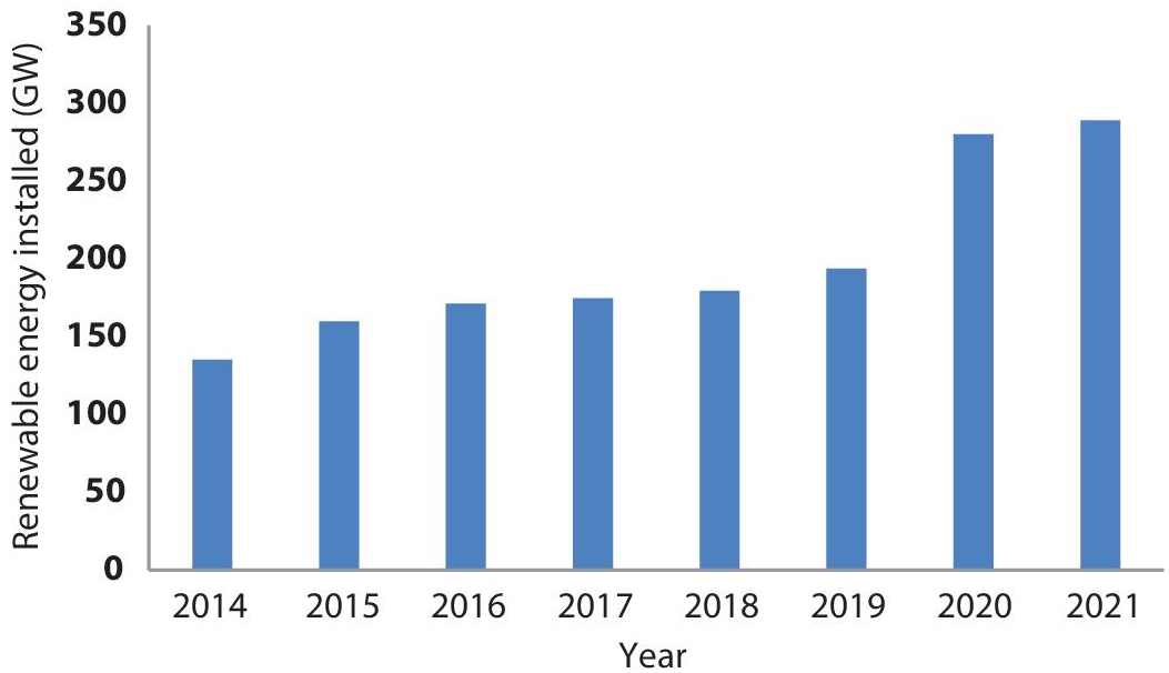
Figure 1.1 Global installed renewable energy capacity.
Electric energy storage entails converting electrical energy into a storable form, and reserving it in different mediums, converting the stored energy back into electrical energy when needed. The integration of ESS into renewable energy systems not only helps to alleviate the intermittency of the renewable source but also reduces energy import during periods of peak demand and provides time-varying energy management. The concept of energy storage for bulk power supply has been in existence as far back as the 1930s when batteries were used in stabilizing and providing support to the power system in different German cities, especially at night [4]. The Electric storage batteries at that time provided the energy needs and emergency capacity during the peak periods when the dynamos, which generated direct current, were out of service.
The International Energy Agency (IEA) in its 2021 report [5] projected a 56% expansion in the global installed energy storage capacity in the next five years, reaching over 270 GW in 2026 with utility-scale batteries projected to experience significant growth in energy storage capacity worldwide. In the study carried out in [6], the report projected that by the end of 2030, the total cumulative installed energy storage capacity would be 741 GWh representing an exponential 31% compound annual growth rate (CAGR) of globally installed energy storage capacity. This is a pointer to the importance of EES to the modern-day power system. The rapid scaling up of energy storage systems is therefore of great importance to address the variability of renewable energy sources as their share of generation increases on the road to a net-zero carbon emission by 2050.
The different services which can be obtained from the integration of ESS include but are not limited to customer energy management services, ancillary services, bulk energy services, transmission infrastructure services and off-grid applications. The integration of EES in both isolated and grid-connected scenarios has multiple advantages ranging from the improvement of power quality to off-grid services such as electric vehicles (EV) and micro-grid stability. With ESS, an opportunity is presented for peak load demand shaving and demand-side management (DSM) ultimately reducing the burden associated with the installation of new generation capacity. EVs are mobile EES and complement the storage capacity of the grid while plug-in-electric (PEV) and smart electric parks have the potential to reduce the peak-to-average ratio and the overall electricity cost in real-time pricing by participation in energy trading of DSM.
The rest of this chapter discusses the different aspects of electric energy storage.
1.2 The Technology of Energy Storage
An ideal energy storage technology should be cost-effective and have a short start-up time, have high roundtrip efficiency, be able to operate at the level of the electric grid with a minimal power rating, and must have an appropriate capacity over power ratio for load shifting. It is important to note that none of the currently existing technologies for ESS has all of the above-mentioned characteristics at once, therefore a trade-off is required depending on need. The choice of storage technology adopted is dependent on factors such as storage duration, end application, the type of energy production, charging and discharging rate, and the depth of the chosen system [7].
Figure 1.2 presents a classification of the different energy storage technologies based on energy usage in a specific form. Each system has its distinguishable characteristic in wattage rating, life cycle, energy density, discharge time, and discharge loss. These characteristics are important to determine the suitability of each storage technology in providing the different services described in Section 1.1.
A. Mechanical energy storage
This storage technology is advantageous because of the flexibility it provides in converting between mechanical and electrical energy forms. Using the principle of potential and kinetic energy, and in some instances, pressurized gas, during off-peak periods electric energy is converted into mechanical energy when energy demand is low and converted back into electrical energy during peak demand for electrical energy. The most commonly available mechanical energy storage are: gravity energy storage systems, compressed air energy storage, flywheel energy storage system, and pumped hydro storage.
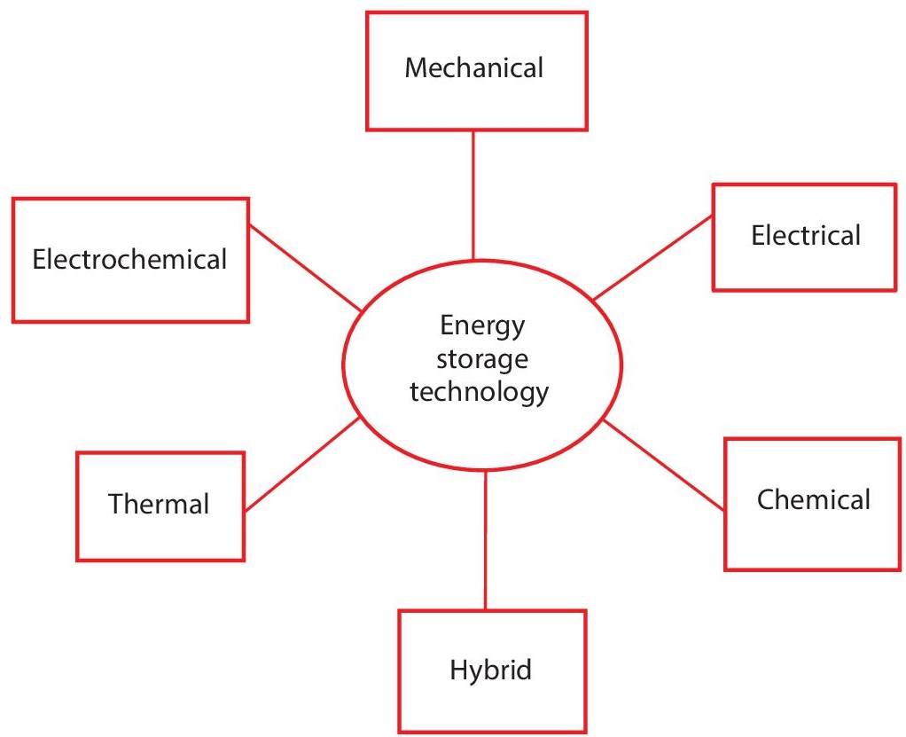
Figure 1.2 Classification of energy storage technologies.
1. Compressed air energy storage (CAES)
The CAES operates on the principle of operation of gas turbine systems. In this energy storage system, energy is stored either as mechanical energy or a combination of thermal and mechanical energy. By compressing air and storing it in an underground space such as a cavern underground, the storage of energy is achieved. Electricity is produced when there is an expansion of the modified gas to rotate the turbine. During off-peak power demand, by utilizing the available excess power, a generator unit or reversible motor is driven. This in turn injects air into the storage unit by running a chain of compressors. The compressed air is released and heated by a heat source during low power generation for load demand before being transferred to the turbine where a recuperation unit recycles the waste heat energy.
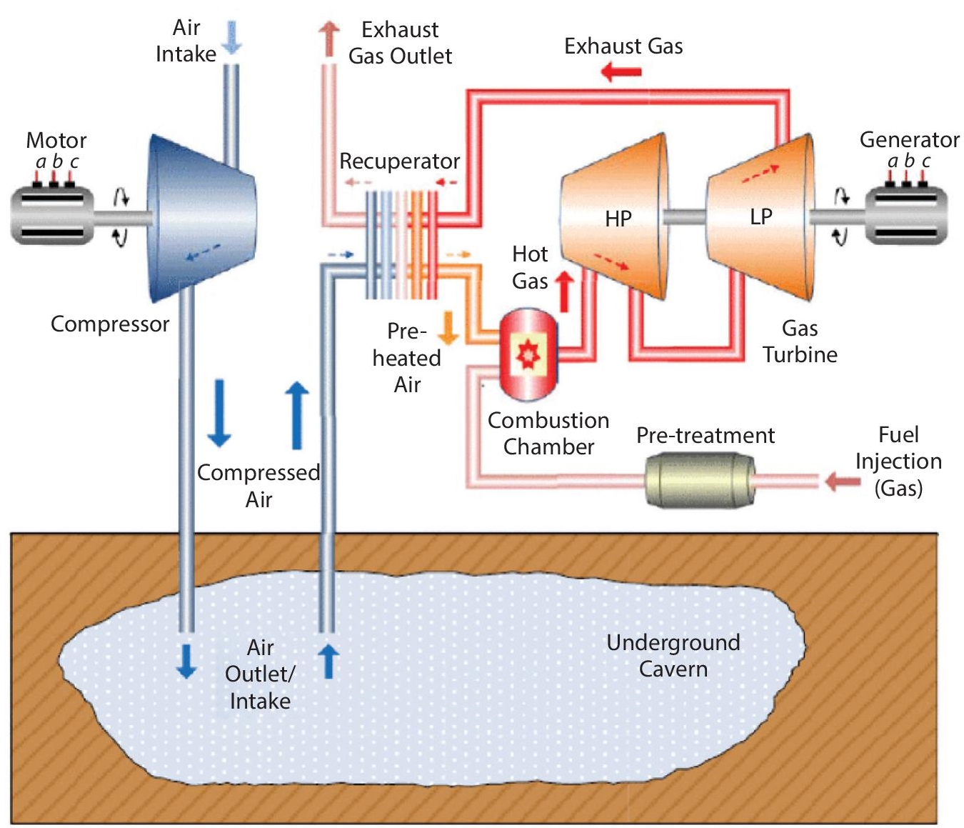
Figure 1.3 Schematic of a large-scale diabatic in-ground cavern CAES system [10].
CAES systems are ideal for small- to large-scale power capacity; however, they can be deployed for large-scale applications involving peak shaving, voltage control, frequency control, and load shifting [8]. CAES can be further classified into diabatic, adiabatic, and isothermal storage [9] based on endothermic and exothermic processes that take place in the compression and expansion of air and heat exchange. System flexibility and high power density are two important characteristics of the Diabatic CAES system that make them the most commercially implemented CAES system. The CAES system can maintain the required system temperature by using external power sources in the heating and cooling of the air as shown in Figure 1.3; this makes them highly efficient. Adiabatic and isothermal CAES systems are well positioned for systems requiring small power density.
CAES systems are highly efficient thermodynamic systems due to the continuous subtraction and addition of heat during compression and expansion, respectively, keeping the air at ambient values. In addition to the ability to smoothen the power output of renewable energy plants, CAES has a high response time. However, a major challenge associated with CAES systems is the selection of a suitable geographical location for such a project.
2. Gravity energy storage (GES) systems
This is an emerging field in energy storage systems that has become a popular alternative to CAES and pumped hydro systems for large-scale power systems. The basic structure of a GES is represented in Figure 1.4. This is a closed system consisting of a piston, generator, reversible turbine/pump, and a container with a returned pipe.
When energy demand is high, water is pushed to flow into the container by the piston to drive the pump/turbine. The kinetic energy of water is then converted into mechanical energy by the turbine, spinning the generator to drive the turbine to produce electricity. A reverse mechanism is initiated during off-peak demand by supplying the excess energy to the motor. The piston is driven to the top of the container by the generated kinetic energy, and the mechanical energy is stored. The GES storage system overcomes the geographical limitation associated with the CAES system.
3. Pumped hydro storage (PHS)
The principle of operation of the PHS is based on storing electrical energy as a form of potential energy by pumping water from the lower side of a reservoir to its higher side when energy demand is lower and vice versa during high energy demand. The performance of a PHS system is generally dependent on the volume and height of available water. Energy storage using PHS is achieved by pumping water uphill using off-peak electricity and then allowing the water to flow downhill, driving the generator to produce electricity for the power grid when the need arises. It is mostly applied in storing and generating electricity using two water reservoirs at different elevations, recompensing high-peak demand. PHS is a commercially available technology representing about 99% of installed EES capacity.

Figure 1.4 Basic structure of a GES [11].
A typical PHS system consists of a generator, upper reservoir, lower reservoir, an inlet valve, penstock valve, motor, and pump. Energy storage time in the PHS is prolonged since the application process is subdivided into a 24-hour scale. The power rating of a PHS varies between 1 MW to 3000 MW at an operating efficiency of 76-85% with practically unlimited life cycles and an operating life span of about 50 years. PHS can be subdivided into three major classifications:
- Open PHS system: This is a pump back system that allows water to continuously flow through the upper and lower reservoir.
- Semi-open PHS: This is made up of one modified lake with continuous through flow and one modified or artificial reservoir.
- Closed loop PHS: This system comprises two non-connected reservoirs and is split by a vertical span.
A significant advantage of the PHS is its remarkable fast response time, which is typically less than a minute, enabling the PHS system to become an important component controlling electrical network frequency in the provision of reserve generation. PHS can act as a stabilizer for power systems consisting of renewable energy sources through its flexible control. The main drawback of the PHS is the constraint of geographical availability.
4. Flywheel energy storage (FES) system
This energy storage system is made of a large cylinder fixed on a stator by magnetic glide bearings that serve as the main component of the FES systems as shown in Figure 1.5. The storage of energy in the FES is a mechanically executed process because the kinetic energy of the rotor mass spins at very high speeds. Through torque control, the energy stored in the flywheel can be reused by reducing the speed of the flywheel while the kinetic energy returns to the electrical motor, functioning as an electric generator. The energy produced by the FES is dependent on the moment of inertia of the rotor and the speed at which it is rotated along its tensile strength and stress restrictions.
FES can be generally classified into low- and high-speed FES systems. Low-speed FES are generally used in power quality applications requiring high power for short durations with a high number of charge-discharge cycles. The high-speed FES system on the other hand has a high energy density in the range of 200 Wh/kg with a high-power density. In contrast to the low-speed FES, which is cheap and commercialized, the high-speed FES is not economical because of the high cost associated with high-speed composite materials, making their use limited to specific longer storage systems.
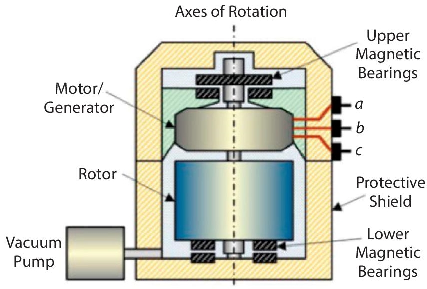
Figure 1.5 Components of a flywheel storage system [12].
Some merits of the FES include a performance rate of about 90% and a longer cycle life (some FES have a capability of over 100 000 full discharge cycle depth), operating at varying temperature conditions with the ability to sustain high power levels. However, a major drawback of the FES is the “flywheel explosion”. This is a scenario where the flywheel tensile strength is exceeded causing the flywheel to shatter, and consequently releasing all of its stored energy at one go.
B. Electrical energy storage (EES) systems
These storage systems can store electrical energy for the production of electric energy and supply the same to the load for use when required. By modifying the magnetic or electric fields using superconducting magnets or capacitors, energy is stored. Since power systems face numerous challenges in the integration of renewable energy sources into the transmission and distribution systems, EES systems have been proposed as an appropriate technology to mitigate these challenges due to its different operating features such as the ability to support micro-grids, reduction of electrical energy import during peak demand period, load balancing and improving power quality. An ultra-capacitor also referred to as a super-capacitor and the super magnetic energy storage are typical examples of an EES.
An ultra-capacitor (UC) stores electrical energy between two conducting electrodes, as shown in Figure 1.6. An advantage of this technology is the absence of any chemical reactions, making it an alternative to the typical capacitor used in general batteries and different electronic applications. The UC operates with a large surface area and molecule thin layer of electrolyte. The UC also has a high peak power output with a high-power density. In comparison to a conventional battery, the UC has a longer calendar life cycle. In power systems applications, there is a possibility of having pulse load, causing severe thermal and power disturbances in the power system and also in micro-grid applications. The UC, because of its fast response to power balancing and leveling with an appropriate control system in place, can help in overcoming these challenges. A major drawback of the UC is its high self-discharge rate and cost.
The operation of the super magnetic energy storage (SMES) is based on the principle of electrodynamics. By circulating current in the superconducting coil while in charging mode, energy is stored in the magnetic field of the SMES device, therefore reducing the superconductivity at low temperatures. The superconducting material present in the SMES is cryogenically cooled. The implication of this is that stored energy can be released back to the network by discharging the coil (discharging mode). A major concern of this storage technology is heat generated by ohmic losses thereby causing thermal instability. The high cost of installation is also a drawback of this technology.
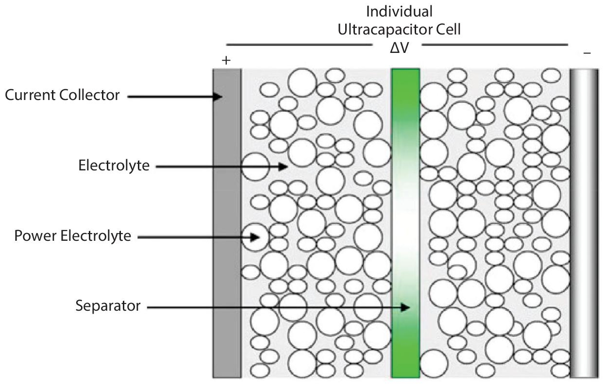
Figure 1.6 Doubled layer supercapacitor [13].
C. Thermal storage systems
The thermal energy storage (TES) systems store energy as either heat or ice, which can be released later when needed. It is an alternative technology to replacing the usage of fossil fuels and meeting the demand for sustainable energy regulations. TES can also be used for applications such as heating or cooling systems in industrial and residential sectors, power generation, and load shifting.
TES consists of a thermal storage tank, a heat transfer medium, and a containment control system. Using distinctive technology, heat is stored and kept in an insulated reservoir. Figure 1.7 depicts a diagrammatic representation of a thermal energy storage system. Stored heat energy is initially transferred and then transformed into electricity using a heat engine cycle [15]. The containment control system is required for the general operation of the reservoir and to monitor the heat transfer medium. It is important to note that TES systems have a very low cycle efficiency in the range of 30-30%; however, this storage technology has a high daily self-discharge and energy rate, environmental friendliness, and the low-cost initial capital, which are some of the advantages of the TES. The schematic of a TES is shown in Figure 1.8 below.

Figure 1.7 Schematic of a SMES [14].
TES systems are broadly classified into two groups based on operating temperature. These are low-temperature TES and high-temperature TES. Low-temperature TES systems are made of cryogenic energy storage and auriferous low-temperature storage typically operating at temperatures below 200 degrees Celsius and find their applications in water heating and solar cooking [17]. The high-temperature TES can be further subdivided into three categories, namely: latent heat system (LHS), absorption and adsorption system (AAS), and sensible heat (SHS). The schematic of a TES is shown in Figure 1.8.
Latent heat storage systems (LHS) cannot be sensed by a change in temperature. An important feature of the LHS is thermal conductivity, improved with metal fillers, metal matrix structures, aluminium shavings, and paraffin. The enthalpy and density of the system is a determinant factor of its storage capacity while the medium of storage can be organic, inorganic, or bio-based.
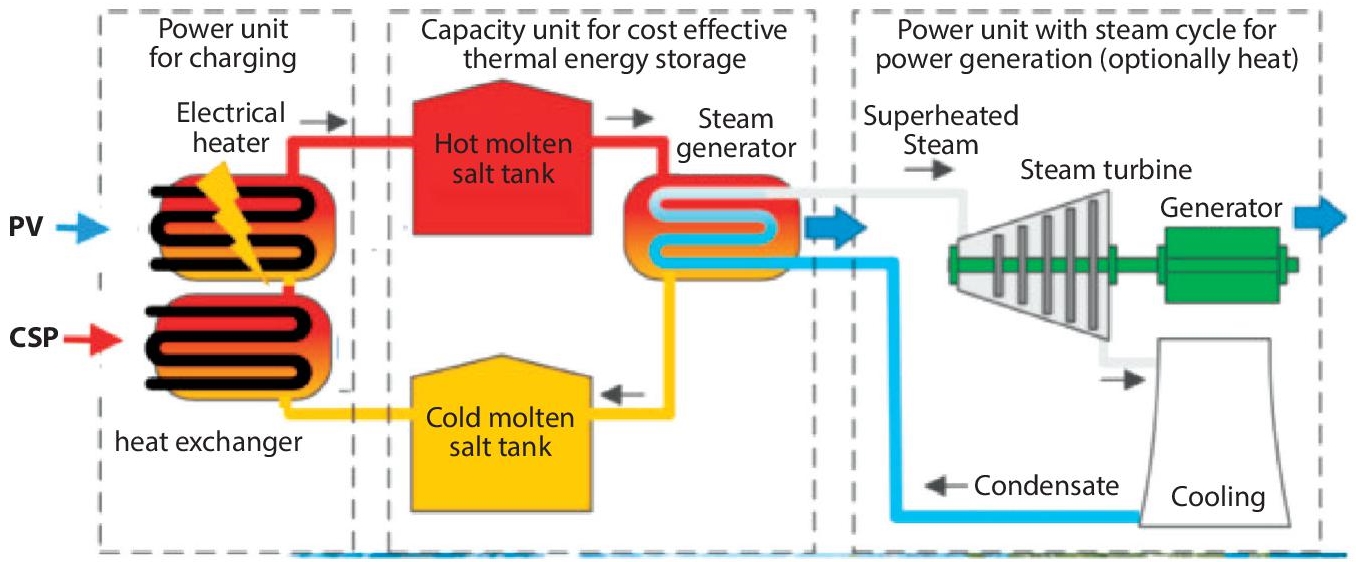
Figure 1.8 Schematic of a TES [16].
The absorption and adsorption system (AAS) is based on a physico-chemical process. This is also referred to as a thermo-chemical storage system. With this storage technology, heat is not stored directly. High energy density is the main advantage of the AAS.
The sensible heat (SHS) can regulate the mass medium and specific heat capacity used for determining the capacity of the storage system during the storage operation processes. The medium of storage used for SHS can be categorized into different forms such as liquid (thermal oil, molten salt, and water), liquid with solid filter material (stone/molten salt), and solid (concrete, metal, and ground). A main drawback of the SHS is the size requirement.
D. Chemical energy storage (CES)
This energy storage system is suitable for storing significant amounts of energy for long periods. In this system, the energy is stored in the chemical bonds between molecules and atoms that are released through the transfer of electrons to directly produce electricity. The most popular sources of chemical fuels for generating electricity and energy transportation systems are coal, ethanol, propane, hydrogen, gasoline, diesel, and liquefied petroleum gas (LPG). The focus of the CES system is hydrogen technology because of its remarkable ability to act as fuel and also store large amounts of electrical energy.
Hydrogen fuel cell (HFC) is a promising alternative for emission-free electricity generation, and its application can be extended to distributed generation and the automobile industry. In comparison to other hydrocarbon fuels, it releases only water vapor into the environment when burned, though it burns faster and contains considerable chemical energy per mass. Its high energy density by weight and low energy density by volume as well as the environmental friendliness of hydrogen has made it become a focus for an energy storage solution. HFC as a medium of energy storage is also very cost-effective considering that hydrogen is readily available.
The application of hydrogen to energy storage systems can be divided into four categories, namely: hydrogen liquefaction, hydrogen adsorption on carbon nanofibers, metal hydrides absorption, and hydrogen pressurization. The pressurization of hydrogen is dependent on the high permeability of materials. A pressure of about 200-250 bars can be stored in a steel tank. However, this is only possible when the ratio of stored hydrogen per unit weight is low since the storage efficiency depends on the increase in temperature. Metal hydride energy storage systems are dependent on the properties of hydrogen absorption of the chemical compounds present. The advantages of this storage system include compatibility and low pressure since most hydrides have higher rates of absorption equivalent to the volume of hydrogen stored to the volume of metal used.
Hydrogen storage technology is preferred for load-shifting applications; however, this technique is costly and its efficiency is the most critical criterion to develop this technology [18].
E. Electrochemical energy storage
In electrochemical storage systems, chemical energy is converted into electrical energy. The process of energy conversion is completed by chemical reactions, while the energy is stored as an electric current for a specific voltage and time. Electrochemical energy storage solutions are the largest group of energy storage devices available. Conventional flow and rechargeable batteries are two technologies for storing energy in electrochemical form. Though there is minimal maintenance needed for batteries, the life expectancy and energy are reduced as a result of a chemical reaction.
Electrochemical storage devices have the advantage of being readily available in different sizes. Examples of the different electrochemical storage devices include lithium-ion, sodium-sulphur, nickel-cadmium, Lead-acid, and flow batteries.
F. Hybrid energy storage
As the name implies, a hybrid energy storage system integrates two or more energy storage technologies, capitalizing on the advantages each of them provides to obtain an excellent solution for a particular application. Since it is practically impossible for single storage technology to have all the advantages, hybrid energy storage is becoming more appealing for modern-day applications such as in micro-grids.
Fast response at high rates for a short duration can be obtained by implementing high-power ESS, while slow response applications for an extended time are achieved with high-energy devices. Micro-grids and power systems need an energy storage solution that can combine the characteristics of a high power and high energy storage system to reduce the problems associated with power quality and improve the stability of the power system. Hybrid energy storage solutions have more complicated control structures than those of single energy storage systems. Some of the possible configurations for hybrid energy storage solutions include the following:
- CAES + SMES
- CAES + FES
- CAES + UC
- CAES + Battery
- Pumped hydro + battery
- Pumped hydro + UC
- Pumped hydro + SMES
- Battery + SMES
- Battery + UC
1.3 Energy Storage and Smart Grids
With the ever-increasing growth in the global population comes a corresponding incremental demand for electrical energy. This has become a challenge not only for the generation of electrical energy but also for its distribution. The growing demand for electrical energy has increased the complexities associated with power grids by increasing the requirements for greater reliability, security, efficiency, and environmental and energy sustainability concerns.
Renewable energy sources (RES) have been proposed as suitable alternatives to conventional fossil power plants in meeting the rising demand for electrical energy. The integration of RES into the power grid has been a source of concern for system operators. This is because of the intermittent nature of such RES and their impact on grid flexibility and balance.
Grid flexibility is the ability of the power system to quickly respond to conditions of unpredicted variations. With conventional power plants, this requirement is made possible by managing the power plant output by rapidly ramping up and down to match the variable and non-predictable electric load. However, with grid integration of RES, the unpredictability of the power system has shifted from the demand side to the generation side and in response to adjustment, flexibility agents have conversely migrated to the demand side. Nevertheless, the current power systems can still make room for flexibility by managing the output of the power plants; with RES this translates into curtailment, therefore, losing clean energy.
To improve power systems and grid flexibility, especially with the grid integration of RES, the concept of smart grids has been introduced. A smart grid is simply a grid that uses modern communication technologies to integrate various elements of an energy system, such as generation and demand, thereby ensuring a balance on both sides. Smart grids ensure that RES can be adequately and optimally fed into the grid. Such a grid can digitally gather, distribute and use provided information on all participants such as suppliers and consumers to improve the reliability, efficiency, and economics of the electricity services [19].
The development of a smart grid comes with the difficult challenge of ensuring a balance between the various variables in connection with dynamic load control powered by the ever-increasing penetration of RES. Installing energy storage solutions can help in achieving the balance between these variables. Energy storage is a very important component of a smart grid and the different ESS available have been well documented in Section 1.2 of this chapter. The choice of ESS for a smart grid is dependent on the number of charging/discharging cycles and the duration of such operations.
ESS plays a complementary role in meeting the goals of an efficient smart grid. The benefits of a smart grid to the power system include less costly interruptions, improved reliability of the power system, an increase in efficiency of power delivery with lower losses in distribution as well as deferred capital expenditure on transmission and generation assets. Energy storage helps the smart grid actualize these merits by negating the need for extra peaking generation by deferring load transmission and distribution upgrades, reducing the transmission congestion fees in deregulated markets by the addition of energy storage to distribution substations, and provision of load capabilities that can help in improving the intermittency of renewable energy sources.
ESS incorporated into the smart grid can also bring cost-saving benefits to the residential consumer from cost savings from peak load management and energy efficiency. On the other hand, the smart grid also provides an opportunity for dispatch of storage units and load control, making RES more valuable to the grid.
A major advantage of a smart grid is the allowance for a wider range of technologies. The use of a fast response ESS such as a flywheel in a smart grid can potentially improve the overall power quality and reliability of the grid by quickly responding to intermittency issues.
Though ESS can facilitate improving power quality and the overall reliability of the grid, it is practically impossible for the ESS to deliver these advantages at every given time. Therefore, the smart grid makes a “smart decision” on the most technical benefit to the grid at any given time, co-optimizing between revenue streams such as ancillary markets and arbitrage [20].
1.4 Energy Storage and Micro-Grids
Micro-grids (MG) are symbols of controllable electric entities containing different loads of distributed energy sources. All typical micro-grids produce electricity from two or more sources, and at least one of such sources is a renewable energy source. Micro-grids are also susceptible to stability and power balance, hence the integration of ESS with a micro-grid is of great benefit to the micro-grid, operating either in an islanded mode or grid-connected mode.
An ESS can be added at various positions in the MG depending on the purpose. The ESS can undertake peak shifting and load leveling functions while acting as a load, supporting peak demand. With the integration of RES, fluctuation mitigation can be performed by the ESS. For an MG with solar photovoltaic and wind power generation, the ESS can enhance the low voltage ride-through capability. It is important to note that the configuration of an ESS in a MG is dependent on the application. For MGs with renewable energy penetration, the ESS can be configured as a distributed ESS or an aggregated ESS.
1. Distributed ESS
In the distributed ESS configuration, the ESS units are coupled directly to the individual distributed generators with different interfaces. Distributed ESS for micro-grids can be further configured to be positioned either on the generator side or the load side of the MG. The ESS positioned on the generator side helps in the generation of smooth output power while on the load side, it helps in the reduction of load variation and energy management. For the generator side distributed ESS, it is usually connected to the DC link of the renewable energy generation unit. A major advantage of the distributed ESS is easy maintenance, optimized cost, and efficiency.
For the load-side distributed ESS, these are usually connected to the local load as the name implies. Variations in load configuration can have a significant impact on the operation of a MG. Therefore, the distributed generators need to be able to follow load change when there is a rapid change in load. If the loads cannot be matched, then the MG becomes unstable. Load following is not very energy efficient since the distributed generators cannot always operate at rated conditions. Therefore, the deployment of distributed ESS can help in smoothing load variation.
2. Aggregated ESS
The aggregated ESS configuration is popular with a lot of MG projects. This is usually a big energy storage facility that offers dedicated housing in the micro-grid. In the aggregated ESS configuration, all the ESS are connected to the terminal of the MG as one aggregated ESS. With the aggregated ESS, there is a large capacity to store a vast amount of energy. Such a storage system may consist of several storage units. Examples of an aggregated ESS is a battery energy storage system (BESS) comprising several battery packages, or a FES made up of several flywheel units. In comparison to the distributed ESS, the aggregated ESS is a better option for suppressing power fluctuations in the MG [21] since the aggregated ESS can stabilize the entire MG, unlike the distributed ESS which works specifically with its own distributed generator.
1.5 Energy Storage Policy Recommendations
Investment tax credits (ITCs) are a very effective way to reduce capital costs and limit exposure to technological and capital risk. This can be applied to energy storage solutions. The implementation of short-term tax policies can help in addressing the high capital cost associated with different energy storage options. ITCs can promote a rapid increase in the storage capacity for services such as frequency regulation. It can also promote the widespread use of technology by boosting market demand and promoting the cost-competitiveness of new technologies against conventional ones. Also, the renewable energy markets have clearly shown the importance of giving tax break incentives, including ITC regimes [22].
ITC, if effectively implemented, can promote the expansion of energy storage in the short run while simultaneously accelerating the reduction of capital costs in the long run. To reach the full potential of an effective smart grid, the importance of an energy storage market characterized by low costs and stable supply cannot be over-emphasized. However, it is important that any ITC program introduced should be able to prevent market volatility in the long term.
Technology risks can be an obstacle to energy storage technologies, and different technically viable energy storage technologies have experienced a delay in deployment because of reluctant developers who are not willing to be the first to carry out such project systems. Pilot and demonstration projects are therefore very important to showcase the practicality of new storage technologies, and successful demonstrations of such technology can help in obtaining private investor funding for the large-scale development of such energy storage systems. It is therefore important for governments across the globe to invest in research and development projects to encourage the development of low-cost effective energy storage solutions. Research and development can reduce the relatively high capital costs of ESS by enhancing the possibility of revenue streams from ESS through increased applications and showing how viable the next generation of energy storage technologies can be.
Also, market formation and support for energy storage solutions are important for the growth of this sector. The various government regulatory agencies in charge of energy should be encouraged to support the deregulation of the energy and power markets, taking necessary steps to ensure stability and market development. Various rules and policies can be developed that monitor storage operations, and evaluate and provide ancillary storage services by providing cost of service rates to owners of storage assets to secure revenue streams and access to capital.
Regional transmission organizations and utilities should be encouraged to participate in the wholesale market, providing access to storage owners by the creation of interconnection standards and compensation schemes for the owners of small-scale storage units. This will in turn boost market competition. By deregulating utilities, and energy markets and supporting greater regulatory market structures, storage owners will have access to the energy markets. This will help in the diversification of the energy markets concerning the services available for exchange and eligible participants.
1.6 Energy Storage: Challenges and Opportunities
Energy storage systems are vital in the ever-increasing demand for energy and large-scale penetration of renewable energy sources in the march towards utilization of low carbon energy sources. However, the large-scale deployment of energy storage technologies still faces technical and economic as well as regulatory challenges.
Currently, policy and regulatory uncertainties, high technological costs, and the energy market structures are some of the challenges facing the large-scale deployment of ESS [23]. The pricing of energy storage is dependent on the energy market structures. By making the storage market competitive, profits can be maximized by storing energy at low prices and releasing it when prices are higher. A competitive energy market inclusive of storage will eliminate investment distortions, thereby encouraging investments in storage capacity. It is also vital to propose clarifications for energy storage systems with active participation from all classes of users to support a dynamic market structure. Governments should aim to facilitate and provide incentives in the energy storage sector considering the regulatory and economic context.
The development of ESS requires innovative and cutting-edge breakthrough research focused on developing more affordable technologies, low cost, longer life span, capacity, and high security for energy storage solutions [24]. Such research should be focused on the simulation of energy storage and operation optimization for multiple applications that can support the application of such storage technologies from a theoretical point of view. The development of demonstration projects that can promote the commercialization and industrialization of such energy storage technologies should be encouraged. There is also the need to encourage collaboration between various research groups focusing on ESS and industry counterparts.
Batteries represent a significant portion of ESS; therefore there is a need to develop strict recycling regulations for batteries aimed at materials recovery. There are lots of inherent opportunities in the local recycling and repurposing of batteries. However, there is a need for research on this to improve the economics of it [5].
1.7 Practical Implementations of Energy Storage Technologies
Energy storage remains an important component of the electricity network, especially for micro-grids and renewable energy sources. Storage systems play the same role across all applications: absorbing generated energy and discharging it later. Energy storage applications include:
- Spinning reserve
- Frequency regulation
- Peak shaving
- Voltage support
- Power quality and
- Capacity firming.
It is important to stress that no two energy storage applications are the same. Different companies offer different technologies for energy storage in live grids across the globe. It is estimated that the global installed storage capacity will expand by at least 56% over the next five years, reaching over 270 GW at the end of 2026 [5]. The bulk of energy storage technologies will be in the form of utility-scale batteries. According to the International Energy Agency (IEA), pumped storage hydro is expected to provide about 42% of global electricity storage capacity with over 40 GW of expansion in the next five years [5].
There are a few examples of practical implementation of energy storage solutions globally. The Golden Valley Electric Association (GVEA) in Alaska uses a nickel-cadmium battery system to supply 27 MW of power for 15 minutes or 46 MW for 5 minutes, allowing ample time for local generation to come online while the Swedish utility company, Falbygdens, utilizes a battery energy storage system to locally produce energy from wind turbine by creating a storage capacity of 75 kilowatts in cycles that last up to 60 minutes. This helps in providing stability to the grid and balancing peak loads during the day. The energy storage market in Germany is growing at a remarkably fast pace. The German utility and automation company, Steag, has inaugurated a 90 MW energy storage system. This project consists of six 15 MW Nidec ASI storage systems, with an investment of USD 100 million. In February 2018, Enel signed an agreement with the German wind energy company, Enertrag AG, and Swiss energy storage solutions company, Leclanché SA, to build and manage a 22 MW lithium-ion battery storage plant in Cremzow in the German state of Brandenburg. With Germany’s ambitious aim of 65% renewable energy deployment by 2030, it is expected that the demand for energy storage will increase at a considerable rate during the forecast period.
1.8 Conclusions
This chapter has discussed the operating principle and characteristics of different energy storage technologies suitable for different power systems applications. Energy storage remains a very important component of the power system with the large-scale penetration of renewable energy into the grid to meet the rising energy demand. The choice of energy storage solution is application specific. ESS also plays a very important role in smart grids. Though ESS can facilitate improving power quality and the overall reliability of the grid, it is practically impossible for the ESS to deliver these advantages at every given time. Therefore, the smart grid makes a “smart decision” on the most technical benefit to the grid at any given time, co-optimizing between revenue streams such as ancillary markets and arbitrage. Though the numerous advantages of ESS have been listed, there are still technical and economic challenges mitigating against the large-scale deployment of ESS.
References
- 1. Salawitch, Ross J., Timothy P. Canty, Austin P. Hope, Walter R. Tribett, and Brian F. Bennett. Paris climate agreement: Beacon of hope. Springer Nature, 2017.
- 2. DeConto, R.M., Pollard, D., Alley, R.B., Velicogna, I., Gasson, E., Gomez, N., Sadai, S., Condron, A., Gilford, D.M., Ashe, E.L. and Kopp, R.E., 2021. The Paris Climate Agreement and future sea-level rise from Antarctica. Nature, 593(7857), pp.83-89.
- 3. IEA (2021), Renewables 2021, IEA, Paris, https://www.iea.org/reports/renewables-2021.htm, 2021.
- 4. Handschin, Edmund, ed. Power system applications of the modern battery storage. Univ., 2004.
- 5. IEA (2021), “How rapidly will the global electricity storage market grow by 2026?” IEA, Paris, https://www.iea.org/articles/how-rapidly-will-the-global-electricity-storage-market-grow-by-2026
- 6. Seferlis, Panos, Petar Sabev Varbanov, Athanasios I. Papadopoulos, Hon Huin Chin, and Jiří Jaromír Klemeš. “Sustainable design, integration, and operation for energy high-performance process systems.” Energy 224 (2021): 120158.
- 7. Choi, Wooyoung, et al. “Reviews on grid-connected inverter, utility-scaled battery energy storage system, and vehicle-to-grid application-challenges and opportunities.” 2017 IEEE Transportation Electrification Conference and Expo (ITEC). IEEE, 2017.
- 8. Luo, Xing, et al. “Overview of current development in electrical energy storage technologies and the application potential in power system operation.” Applied Energy 137 (2015): 511-536.
- 9. Cheng, Jie, and F. Fred Choobineh. “A comparative study of the storage assisted wind power conversion systems.” 2017 6th International Conference on Clean Electrical Power (ICCEP). IEEE, 2017.
- 10. Molina, Marcelo G. “Energy storage and power electronics technologies: A strong combination to empower the transformation to the smart grid.” Proceedings of the IEEE 105.11 (2017): 2191-2219.
- 11. Berrada, Asmae, Khalid Loudiyi, and Izeddine Zorkani. “System design and economic performance of gravity energy storage.” Journal of Cleaner Production 156 (2017): 317-326.
- 12. Hadjipaschalis, Ioannis, Andreas Poullikkas, and Venizelos Efthimiou. “Overview of current and future energy storage technologies for electric power applications.” Renewable and Sustainable Energy Reviews 13.6-7 (2009): 1513-1522.
- 13. Wang, Guoping, Lei Zhang, and Jiujun Zhang. “A review of electrode materials for electrochemical supercapacitors.” Chemical Society Reviews 41.2 (2012): 797-828.
- 14. Molina, Marcelo G. “Distributed energy storage systems for applications in future smart grids.” 2012 Sixth IEEE/PES Transmission and Distribution: Latin America Conference and Exposition (T&D-LA). IEEE, 2012.
- 15. Chen, Haisheng, et al. “Progress in electrical energy storage system: A critical review.” Progress in Natural Science 19.3 (2009): 291-312.
- 16. Kramer, Susan. “Morocco Pioneers PV with Thermal Storage at 800 MW Midelt CSP Project.” SolarPACES, April 25 (2020).
- 17. Gil, Antoni, et al. “State of the art on high-temperature thermal energy storage for power generation. Part 1—Concepts, materials, and modelization.” Renewable and Sustainable Energy Reviews 14.1 (2010): 31-55.
- 18. Kousksou, Tarik, et al. “Energy storage: Applications and challenges.” Solar Energy Materials and Solar Cells 120 (2014): 59-80.
- 19. U.S. Department of Energy, 2012. Smart Grid/Department of Energy.
- 20. Roberts, Bradford P., and Chet Sandberg. “The role of energy storage in development of smart grids.” Proceedings of the IEEE 99.6 (2011): 1139-1144.
- 21. Wei L, Joos G. Performance comparison of aggregated and distributed energy storage systems in a wind farm for wind power fluctuation suppression. In: Power engineering society general meeting. IEEE. Tampa, FL, USA: 2007.
- 22. Sawin, Janet, and Christoper Flavin. “Policy lessons for the advancement & diffusion of renewable energy technologies around the world.” trabajo presentado en la International Conference for Renewable Energies, Bonn. 2004.
- 23. Bhatnagar, Dhruv, et al. Market and policy barriers to energy storage deployment. No. SAND2013-7606. Sandia National Lab. (SNL-NM), Albuquerque, NM (United States); United States., Washington, DC, 2013.
- 24. S. Dhundhara, Y. P. Verma, and A. Williams, “Techno-economic analysis of the lithium-ion and lead-acid battery in microgrid systems,” Energy Convers. Manag., vol. 177, pp. 122–142, 2018.
Note
- Email: [email protected]