
4
Energy Storage Units for Frequency Management in Nuclear Generators-Based Power System
Boopathi D.1*, Jagatheesan K.1, Sourav Samanta2, Anand B.3 and Satheeshkumar R.1
1Paavai Engineering College, Tamil Nadu, India
2University Institute of Technology, University of Burdwan, West Bengal, India
3Hindusthan College of Engineering and Technology, Tamil Nadu, India
Abstract
In this chapter, the Load Frequency Management (LFM) of an interconnected nuclear power network with an energy storage unit (ESU) is explained. The impact of the ESU in the proposed power system during emergency loading is analyzed in detail. A Proportional Integral Derivative (PID) controller is designed and implemented as a secondary controller for the LFM of the proposed power network. The Ant colony optimization (ACO) technique is utilized to optimize the gain parameters of the proposed controller. The impact of various ESUs such as battery energy storage system (BESS), fuel cell (FC), redox flow battery (RFB), ultra-capacitor (UC), proton exchange membrane (PMC) based FC, and supercapacitor energy system (SCES) is analyzed in detail. The proposed optimization technique-based controller is performed well and regulates the stability of the system frequency, in terms of quick settling time, minimal peak over, and undershoots.
Keywords: Energy storage units, load frequency management, ant colony optimization, interconnected power system, frequency deviation
4.1 Introduction
In recent years the development of industries and modernization of domestic life has created more power requirements. To balance the difference between power requirement and power generation, countries are moving towards installing new power plants and increasing the standing power plant capacity. While increasing the power generating capacity, due to the system’s complex more power quality issues occur during the emergency loading time. The LFM is a scheme to control and maintain the frequency-related issues in the power grid. Many research people are handling these issues by implementing various secondary controllers, optimization techniques to optimize the controller gain parameters, and energy storage units. The purpose of the following literature review is to analyze and find the research gap in the LFM.
Improved salp swarm computation algorithm has been proposed for LFM of microgrid (MG) power system which includes renewable energy sources (wind and solar), and energy storage units like BESS, FC by [1]. The author in [2] studied the impact and performance of the various energy storage systems (ESS) with grid-connected power systems. An advanced controller is developed for LFM of power network which has PMC-based FC in [3]. Multiverse optimizer (MVO) based PID controller has been implemented to perform LFM of an interconnected power system in [4]. UC and RFB play a vital role in [5] the LFM of an isolated hybrid power network. The author in [6] analyzed the impact of the SMES. RFB and HAE with single area nuclear power plant for LFM by developing an ACO – PID controller.
An opposition-based Harmonic Search (OHS) based integral controller was developed by the authors in [7] to perform LFM for interconnected multi-source power network incorporated with RFB. The author in [8] has proposed and analyzed the impact of a hybrid energy storage system (HESS) consisting of supercapacitor and RFB unit by implementing the neural network-based PID controller. In [9] a CO - PID controller to perform LFC of wind power form with BESS and FC is implemented. A multi-area microgrid which consists of RFB and SMES is investigated by [10] for LFM. CES and an SMES incorporated microgrid is examined by PSO – PID controller in [11]. An integral controller is utilized as a secondary controller for single area power system with BESS and supercapacitor in [12]. To perform LFM in a microgrid consisting of FC, Flywheel a fuzzy logic controller (FLC) is implemented by [13].
A CES incorporated power system is examined by hybrid PSO and GA-based PID controller for LFM in [14]. The author [15] investigated a 2-area interconnected power system with CES by FLC. Flower pollination algorithm-based PID controller is designed by [16] to implement LFM in microgrid with CES. A classical PI controller is designed by [17] for LFM of hybrid microgrid with PEM FC. The author in [18] investigated a single and double reheated thermal system with SMES and RFB by stochastic PSO – PID controller. An SMES incorporated power system is examined in [19] with ACO – PID controller. FC, BESS incorporated microgrid power network is investigated by PSO – PID controller by the author in [20]. A PSO – PID controller is developed for the LFM of the single area power system with BESS in [21]. An interconnected multiple sources power network is examined by PSO – PI controller in [22]. In [23] AGC of a real-time implementation of BESS in South Korea was studied. The author in [24] developed a MVO – PI controller for LFC of RFB incorporated power system. A interconnected thermal + hydro + gas power network is examined by whale optimization algorithm tuned PI controller in [25]. The summary of the literature review is shown in Table 4.1.
Table 4.1 Summary of literature review.
| Author/Year | Energy storage units | Computation techniques/ Controller utilized | System considered | Ref. no. |
|---|---|---|---|---|
| Sahu et al., 2018 | BESS, FC | Improved Salp swarm/fuzzy PID | Microgrid – Micro turbine + Diesel engine generator | [1] |
| Akram et al., 2020 | ESS | Model optimizer | Single area thermal + wind + PV+ energy storage system | [2] |
| Yildirim, B., 2021 | BESS, PEM, FC | Advanced controller | Microgrid – PV+wind+Fuelcell+BESS | [3] |
| Sharma et al., 2021 | RFB | Multiverse optimizer/PID | Six area power system with fuel cell | [4] |
| Mudi et al., 2021 | RFB, UC | Multiverse optimizer/PID | Solar thermal + PV | [5] |
| Dhanasekaran et al., 2020 | RFB, HAE, SMES | Ant Colony Optimization/ PID | Single area nuclear | [6] |
| Shankar et al., 2016 | RFB | Opposition-based Harmonic Search – I | Thermal + Hydro + Gas | [7] |
| Xu et al., 2017 | Supercapacitor, RFB | Hammerstein-type neural network/PID | Thermal | [8] |
| Boopathi et al., 2022 | BESS, FC | Ant Colony Optimization/ PID | Wind | [9] |
| Sadoudi et al., 2021 | RFB, SMES | Elephant Herding Optimization PIDN | Microgrid (Diesel + PV + wind) | [10] |
| Ali et al., 2018 | CES, SMES | Particle Swarm Optimization/PID | Micro hydro power system | [11] |
| Zhou et al., 2017 | Supercapacitor, BESS | Classical Integral | Microgrid with RESs | [12] |
| Abazari et al., 2019 | FC, Flywheel | Fuzzy logic controller | Diesel , wind + energy storage system | [13] |
| Khadanga and Kumar, 2019 | CES | Hybrid Particle Swarm Optimization & Genetic Algorithm/PID | Thermal + Hydro + Gas | [14] |
| Arya, 2019 | CES | Fuzzy Logic Controller | Thermal + Hydro | [15] |
| Ali et al., 2018 | CES | Flower pollination algorithm/PID | Micro hydro | [16] |
| Sharma and Mishra, 2017 | PEM FC | Classical PI | PV | [17] |
| Jagatheesan et al., 2016 | RFB, SMES | Stochastic Particle Swarm Optimization/PID | Thermal | [18] |
| Jagatheesan et al., 2018 | SMES | Ant Colony Optimization/ PID | Thermal | [19] |
| Boopathi et al., 2021 | FC, BESS | Particle Swarm Optimization/PID | Thermal + PV + wind | [20] |
| Kumarakrishnan et al., 2020 | BESS | Particle Swarm Optimization/PID | Thermal + hydro + gas + nuclear | [21] |
| Dhundhara and Verma, 2018 | CES | Particle Swarm Optimization | Thermal + hydro + gas | [22] |
| Jin et al., 2016 | BESS | - | Thermal + hydro + nuclear | [23] |
| Kouba et al., 2016 | RFB | MVO/PI | Wind + diesel | [24] |
| Kumar and Sharma, 2020 | CES | Whale optimization/PI | Thermal + hydro + gas | [25] |
The literature review helped to find the impact and role of ESUs in the power system for LFM. In recent days, renewable energy sources (RESs) are more penetrating in the power generation sector. While used in the power system, the ESU much needs one, because most of the RESs provide non-linear power output. To regulate that power output, ESU is utilized. Other power systems also use the ESU to compensate for the small load demands. In the literature review, most of the energy storage units the researchers are investigating are in RESs-based power system only. So, in this chapter the research gap is filled by analyzing the energy storage units’ impact on nuclear power plants.
4.1.1 Structure of the Chapter
This chapter is structured as per the following plan: section 4.1 provides the complete and detailed analysis of the ESU in the power system by literature review. A proposed Simulink model, different ESU which are analyzed in the chapter is given in section 4.2. The basic structure and role of controllers are explained in section 4.3. Section 4.4 discusses the optimization algorithm implemented to tune the controller. The detailed impact analysis of ESU is given in section 4.5. Results and discussion are in section 4.6.
4.1.2 Objective of the Chapter
- To identify and design an energy storage unit, which can be incorporated with the power system.
- To develop a secondary controller to study the LFM in the power system.
- Analysis of the performance and contribution of the ESU in the power system for LFM.
4.2 Investigated System Modeling
Nuclear power is one of the upcoming electrical power generators. Because of the shortage of fossil fuels, renewable energy sources have become part of electrical power generation; due to the environmental factor the renewable sources are not able to generate the power to overcome the load demand. So large power production may depend on nuclear power plants. In the report issued in January 2020 titled “Optimal Generation Capacity Mix for 2029-30”, the Central Electricity Authority India planned to install 12,000 MW capacity of nuclear power plants in India. A two-area nuclear power plant is proposed in the chapter to investigate the performance of the system and the impact of the ESU with the proposed power system. The proposed model is shown in Figure 4.1a and, the isolated model of the nuclear power plant is shown in Figure 4.1b [6].
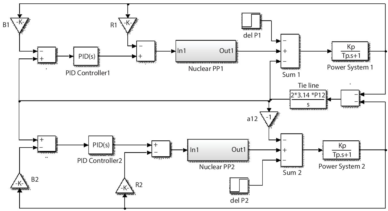
Figure 4.1a Proposed Simulink model of power system.

Figure 4.1b Isolated model of nuclear power plant.
The nuclear power plant static model was designed by the governor, one High Pressure (HP), two parallel Low Pressure (LP) turbines. To improve the performance of the turbine a reheater is connected in between the turbines.
4.2.1 Battery Energy Storage System (BESS) Model
The BESS unit is designed to address the critical loads’ instantaneous energy needs in microgrid systems. At the time of the underloading the battery acted as load and gets charged. At the time of overloading the battery acted as source. GBESS in equation 4.2 [3] creates the transfer function provided by the BESS device’s transient response. The time constant of BESS is represented by TBESS in equation 4.1. BESS incorporated model is shown in Figure 4.2a and the mathematical expression of BESS is given in Figure 4.2b.


Figure 4.2a Proposed power system model with BESS.
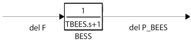
Figure 4.2b Transfer function model of BESS.
4.2.2 Fuel Cell (FC) Model
Some indicators will exceed their standards due to sudden changes in load, reducing their service life. As a result, an energy management unit with an energy storage device is required to improve the fuel cell’s dynamic performance, reduce damage caused by rapid load change, and extend service life. Figure 4.3 depicts FC incorporated into the proposed model. FC is supported to balance the power demand as power source.
4.2.3 Redox Flow Battery (RFB) Model
RFB is one of the most visible electrochemical static Energy Storage (ES) devices. The term “redox” refers to the chemical and oxidation reactions that the RFB uses to store energy in the electrolyte solution. During the oxidation process, an electron is discharged from a high potential state to the negative terminal of the battery. To perform useful work, the electron travels through an external circuit. Finally, the electron is accepted by the positive side of the battery. The way new electrolytes are consistently directed into the battery to maintain energy levels gives it an advantage over other ES devices. RFBs contain sulphuric acid (H2SO4) and vanadium pentoxide ions (V2O5) as an electrolyte [4]. The basic chemical reactions that occur are shown in equations 4.2 and 4.3.
At positive electrode

Figure 4.3 Proposed power system model with FC.
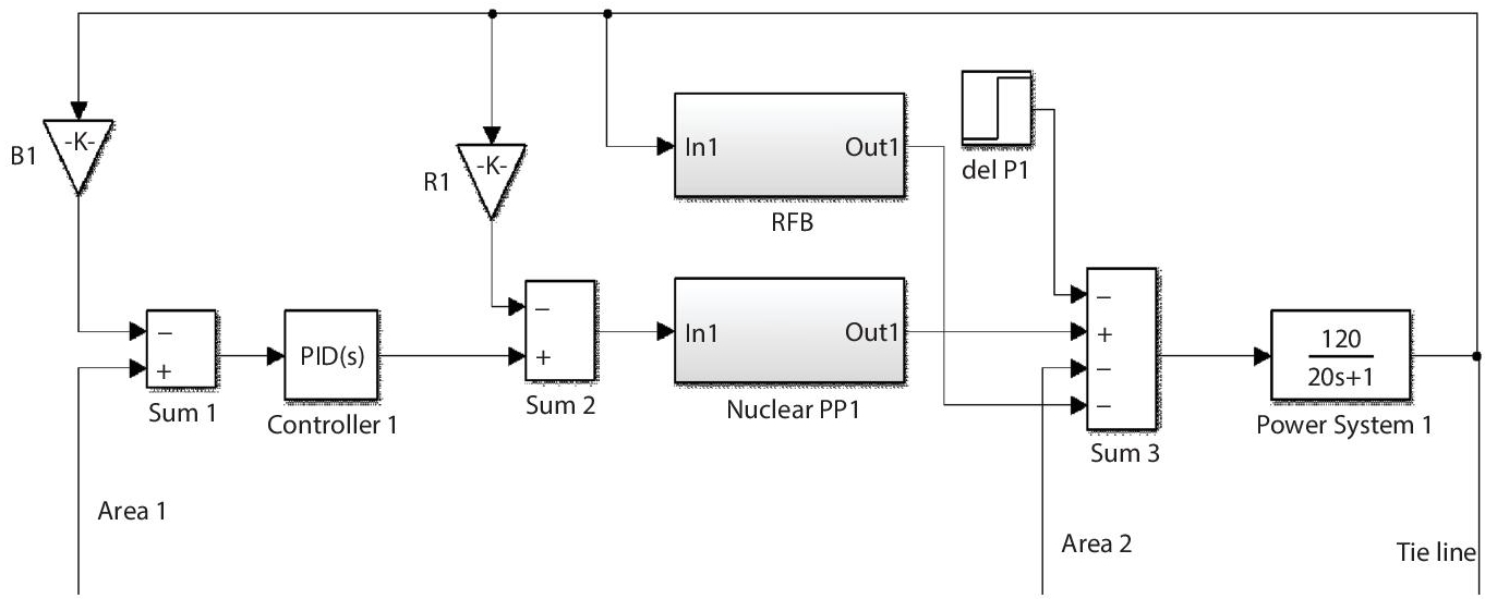
Figure 4.4a Proposed power system model with RFB.

Figure 4.4b Transfer function model of RFB.
At negative electrode
RFB has a wide range of applications in the frequency regulation problem. When there is a delay in the governor response due to their drowsy reaction, RFBs provide a brisk and fast response and thus suit well for frequency regulation in system. They are suitable for applications with power ratings ranging from tens of KW to tens of MW in [4]. RFB connected model and the RFB transfer function is shown in Figures 4.4a and 4.4b.
4.2.4 Proton Exchange Membrane (PEM) Based FC Model
In this power system, a proton exchange membrane (PEM) based fuel cell is used. PEM fuel cells are the most common fuel-cell type and are widely used in a variety of applications. PEM – FC consists of the fuel cell, inverter, and interlinked device. The incorporation of the PEM-FC with the proposed system and the mathematical expression of the PEM-FC is given in Figures 4.5a and 4.5b, respectively.
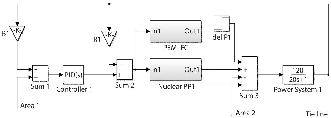
Figure 4.5a Proposed power system model with PEM-FC.

Figure 4.5b Transfer function model of PEM-FC.
4.2.5 Ultra-Capacitor (UC) Model
The capacitor stores electrical energy in the form of electrostatic energy. The amount of energy storage is directly proportional to the voltage applied between the plates (V) charge stored in the capacitor is Q ∝ V. The capacitor proportional constant is (C) is called capacitance. The charge on a capacitor is given in equation 4.4.
Where
- Q = Charge (Coulombs)
- C = Capacitance (Farads)
- V = Voltage (Volts)
Another type of capacitor, an ultra-capacitor (UC), has large conductive plates (electrodes). UC has excellent energy storage capacity because of high capacitance up to hundreds of farads, a small gap between the electrode and, electrode have high surface area. As previously stated, an ultra-capacitor is an electrochemical device that stores charge electrostatically by utilizing two porous electrodes, typically made of activated carbon immersed in an electrolyte solution. This configuration effectively creates two capacitors, one at each carbon electrode and linked in series.
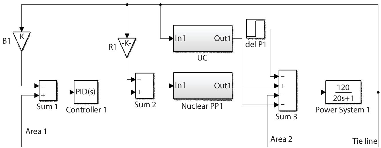
Figure 4.6a Proposed power system model with UC.

Figure 4.6b Transfer function model of UC.
UC incorporated proposed model is shown in Figure 4.6a and the transfer function model of the UC is given in Figure 4.6b [5].
4.2.6 Supercapacitor Energy Storage (SCES) Model
The SCES unit is an energy storage device that is integrated with a power conversion system that includes a rectifier/inverter, capacitor, and some protective. SCES incorporated system model and transfer function model is shown in Figures 4.7a and 4.7b, respectively. SCES also acted as ultra-capacitor its charges during underloading and discharging during overloading.
4.3 Controller and Cost Function
In the implementation process of the LFC/LFM scheme in the power system, the secondary controller plays a major role. The primary controller in the power system is not suitable for controlling/maintaining the system stability at sudden loading conditions. In this chapter, the PID controller is designed for implementing LFC/LFM. The PID controller is a commonly used industrial-based controller. It is designed by three separate controllers (Proportional, Integral, Derivative). The mathematical function of the PID controller is given in equation 4.5. A simple structure of the PID controller is shown in Figure 4.8.

Figure 4.7a Proposed power system model with SCES.
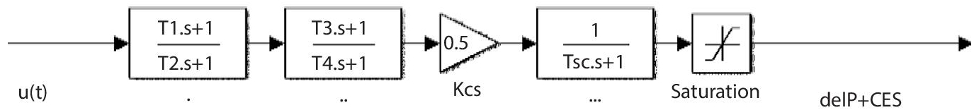
Figure 4.7b Transfer function model of the SCES.

Figure 4.8 Simple structure of PID controller.

The objective function is playing an important role in the controller tuning process for minimizing the error signal and helps to find the fitness value J. In this chapter, the integral time absolute error (ITAE) cost function is involved to get an optimal controller gain parameter. The mathematical expression of the ITAE cost function is given in equation 4.6.

4.4 Optimization Methodology
Ant colony optimization (ACO) technique is one of the most popular optimization techniques in various fields. The development of the technique was inspired by the food searching process of ants and also the finding of the shortest path between food source and nest. First this technique is implemented to solve the traveling salesman problem. By implementing the ACO technique the proposed PID controller gain parameters are optimized. The optimized controller gain parameters are presented in Table 4.2 [6, 19].
Table 4.2 ACO technique optimized proposed controller gain parameters.
| Investigated system/ Gain parameters of the proposed controller | PID controller 1 | PID controller 2 | ||||
|---|---|---|---|---|---|---|
| KP | KI | KD | KP | KI | KD | |
| System without ESU | 0.99 | 1 | 0.31 | 0.74 | 0.87 | 0.17 |
| System with BESS | 1 | 0.99 | 0.02 | 0.99 | 0.99 | 0.44 |
| System with CES | 0.97 | 0.98 | 0.18 | 0.98 | 0.71 | 0.6 |
| System with FC | 0.95 | 0.99 | 0.29 | 0.53 | 0.9 | 0.19 |
| System with PEM-FC | 0.86 | 1 | 0.18 | 0.81 | 0.93 | 0.95 |
| System RFB | 0.99 | 0.96 | 0.02 | 0.87 | 1 | 0.05 |
| System UC | 0.96 | 1 | 0.29 | 0.37 | 0.62 | 0.48 |
4.5 Impact Analysis of Energy Storage Units
The proposed power system Simulink model is investigated with 1% of SLP in the MATLAB 2014a simulating platform. The impact analysis of each ESU is studied in this section in detail as given below:
4.5.1 Impact of BESS
To investigate the impact of the BESS for LFC of the proposed interconnected power system, BESS is incorporated with the proposed system which is shown in section 4.2. The impact of the BESS is analyzed by comparing the system response with/without BESS in the proposed power system. The frequency oscillation comparison of area 1 and area 2 is given in Figures 4.9a and 4.9b, respectively. The numerical values in Figures 4.9a and 4.9b are presented in Table 4.3.

Figure 4.9a delF1 comparison of with/without BESS.
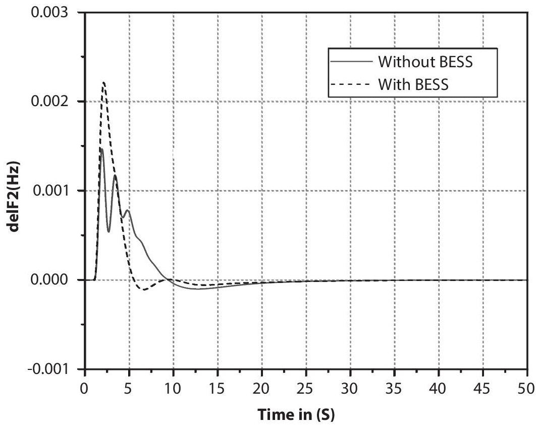
Figure 4.9b delF2 comparison of with/without BESS.
Table 4.3 Time domain-specific parameters of del F1 & F2 of proposed system with/without BESS.
| Time domain-specific parameter/System | del F1 | del F2 | |||||
|---|---|---|---|---|---|---|---|
| TS (s) | POS(Hz) | PUS(Hz) | TS (s) | POS(Hz) | PUS(Hz) | ||
| System without BESS | 15.2 | 7.5 × 10⁻⁴ | 0.0122 | 48 | 1.46 × 10⁻³ | 1 × 10⁻⁴ | |
| System with BESS | 15 | 1.6 × 10⁻³ | 0.0141 | 35 | 2.21 × 10⁻³ | 1 × 10⁻⁴ | |
The impact analysis of the BESS is given in Figures 4.9a and 4.9b and numerical values in Table 4.3 clearly show that the BESS is helping to settle the frequency deviation F1 (15s< 15.2s) & F2 (35s<48s) of the power system at emergency conditions. Where T(s) is settling time of the system frequency, POS referred as overshoot, and PUS is denoted as undershoot.
4.5.2 Impact of FC
To analysis the impact of the FC for the LFM of the proposed power system, an FC is interconnected with the nuclear power plant. The impact analysis of the FC in the proposed system is given in Figures 4.10a and 4.10b, and the nominal values from the graph are reported in Table 4.4.
The impact analysis of the FC is given in Figures 4.10a and 4.10b and numerical values reported in Table 4.4 clearly show that the FC is helping to settle the frequency deviation F1 (15.2s = 15.2s) & F2 (35s < 48s) quick in the area 2 and provide the minimal peak values of the system at emergency conditions.

Figure 4.10a delF1 comparison of with/without FC.

Figure 4.10b delF2 comparison of with/without FC.
Table 4.4 Time domain-specific parameters of del F1&F2 of proposed system with/without FC.
| Time domain-specific parameter/ System | del F1 | del F2 | ||||
|---|---|---|---|---|---|---|
| TS (s) | POS(Hz) | PUS(Hz) | TS (s) | POS(Hz) | PUS(Hz) | |
| System without FC | 15.2 | 7.5 × 10⁻⁴ | 0.0122 | 48 | 1.46 × 10⁻³ | 1 × 10⁻⁴ |
| System with FC | 15.2 | 5.5 × 10⁻⁴ | 0.009 | 35 | 1.4 × 10⁻³ | 1 × 10⁻⁴ |
4.5.3 Impact of RFB
To study and analyze the impact of the RFB, an RFB unit is incorporated with the proposed system. The del F is fed as input to the RFB. The frequency deviation of area 1 and area 2 graphically is shown in Figures 4.11a and 4.11b respectively. Numerical values in Figure 4.11 are reported in Table 4.5.

Figure 4.11a delF1 comparison of with/without RFB.

Figure 4.11b delF2 comparison of with/without RFB.
Table 4.5 Time domain-specific parameters of del F1&F2 of the proposed system with/without RFB.
| Time domain-specific parameter/ System | del F1 | del F2 | ||||
|---|---|---|---|---|---|---|
| TS (s) | POS(Hz) | PUS(Hz) | TS (s) | POS(Hz) | PUS(Hz) | |
| System without RFB | 15.2 | 7.5 × 10⁻⁴ | 0.0122 | 48 | 1.46 × 10⁻³ | 1 × 10⁻⁴ |
| System with RFB | 30 | 6.5 × 10⁻⁴ | 5.2 × 10⁻³ | 41 | 9 × 10⁻⁴ | 1.7 × 10⁻⁴ |
From the response comparison of with/without RFB in the proposed power system in Figures 4.11a and 4.11b, numerical values in Table 4.5 clearly show that the RFB provides the improvement in the frequency deviation area 2 (41s < 48s) and minimize the peak shoots in both areas.
4.5.4 Impact Analysis of the PEM-FC
The performance of the PEM-FC for LFC of interconnected power system is the analysis in this section. PEM-FC is an interconnected with the proposed power system (two-area nuclear) and the system performance is analyzed. The frequency deviation of area 1 and 2 are represented in Figures 4.12a and 4.12b, respectively. The numerical values in Figures 4.11a and b are reported in Table 4.6.
The impact of the PEM-FC for the LFM of the proposed power system is analyzed in detail and reported graphically in Figures 4.12a and b. The numerical values of Figures 4.12a and b is in Table 4.6. It is clearly demonstrated that the PEM FC performed well in the proposed system for LFM. It provides a better response in terms of fast settling of the frequency oscillation F1 (11s < 15.2s) & F2 (35s < 48s) and minimal peak values.

Figure 4.12a delF1 comparison of with/without PEM-FC.
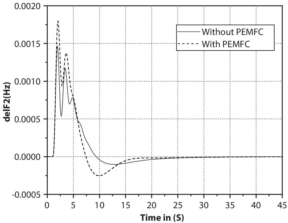
Figure 4.12b delF2 comparison of with/without PEM-FC.
Table 4.6 Time domain-specific parameters of del F1&F2 of proposed system with/without PEM-FC.
| Time domain-specific parameter/ System | del F1 | del F2 | ||||
|---|---|---|---|---|---|---|
| TS (s) | POS(Hz) | PUS(Hz) | TS (s) | POS(Hz) | PUS(Hz) | |
| System without PEM-FC | 15.2 | 7.5 × 10⁻⁴ | 0.0122 | 48 | 1.46 × 10⁻³ | 1 × 10⁻⁴ |
| System with PEM-FC | 11 | 1.5 × 10⁻³ | 0.013 | 35 | 1.8 × 10⁻³ | 2.5 × 10⁻⁴ |
4.5.5 Impact Analysis of UC
The impact of the UC in the proposed system for LFC is studied, and the frequency deviation comparison of area 1 and 2 is shown in Figures 4.13a and 4.13b, respectively. The nominal values in Figures 4.13a and 4.13b are reported in Table 4.7.

Figure 4.13a delF1 comparison of with/without UC.

Figure 4.13b delF2 comparison of with/without UC.
Table 4.7 Time domain-specific parameters of del F1&F2 of proposed system with/without UC.
| Time domain-specific parameter/ System | del F1 | del F2 | ||||
|---|---|---|---|---|---|---|
| TS (s) | POS(Hz) | PUS(Hz) | TS (s) | POS(Hz) | PUS(Hz) | |
| System without UC | 15.2 | 7.5 × 10⁻⁴ | 0.0122 | 48 | 1.46 × 10⁻³ | 1 × 10⁻⁴ |
| System with UC | 15 | 1.65 × 10⁻³ | 0.014 | 35 | 2.2 × 10⁻³ | 1.1 × 10⁻⁴ |
The performance of the UC in the proposed system for LFM is clearly demonstrated in Figures 4.13a and 13b. The nominal values of Figure 4.13 are reported in Table 4.7. From Figure 4.13 and Table 4.7, the UC has made a positive impact in the proposed system in terms of quick setting time F1 (15s < 15.2s) & F2 (35s < 48s) and minimal peak values.
4.5.6 Impact Analysis of SCES
To study and analyze the impact of the SCES, a SCES unit is incorporated with the proposed system. The del F is fed as input to the SCES. The frequency deviation of area 1 and 2 are graphically shown in Figures 4.14a and 4.14b, respectively. Numerical values in Figure 4.14 are reported in Table 4.8.

Figure 4.14a delF1 comparison of with/without SCES.

Figure 4.14b delF2 comparison of with/without SCES.
Table 4.8 Time domain-specific parameters of del F1&F2 of proposed system with/without SCES.
| Time domain-specific parameter/ System | del F1 | del F2 | ||||
|---|---|---|---|---|---|---|
| TS (s) | POS(Hz) | PUS(Hz) | TS (s) | POS(Hz) | PUS(Hz) | |
| System without SCES | 15.2 | 7.5 × 10⁻⁴ | 0.0122 | 48 | 1.46 × 10⁻³ | 1 × 10⁻⁴ |
| System with SCES | 29 | 5.5 × 10⁻⁴ | 9 × 10⁻³ | 43 | 7.6 × 10⁻⁴ | 1.4 × 10⁻⁴ |
From Figures 4.14a, 4.14b, and Table 4.8 the SCES has not made a positive impact on the proposed power system for LFC. Because the SCES incorporated model takes more time to settle the oscillation F2 (43s < 48s) in the system frequency at emergency conditions than the system without SECS.
4.6 Result and Discussion
The various energy storage units such as BESS, FC, RFB, PEM-FC, UC, and SCES are incorporated with the proposed two-area nuclear power system to analyze the impact of each ESU to implement the LFM scheme to maintain the system stability and frequency during emergency loading conditions. The comparative analysis of del F1, del F2, and tie-line power deviation is plotted in the 4.15a – 4.15c, respectively. From section 4.5 and Figure 4.15, the impact of the ESU is clearly shown, the PEM-FC performed well over other ESUs. PEM-FC helps to minimize the peak shoot and bring back the frequency to the normal state from oscillation.
From the frequency deviation comparison of the proposed power system incorporated with various ESU in Figures 4.15a, 4.15b and tie-line power flow comparison in Figure 4.15c it is strongly demonstrated that energy storage units create some impact in the system for LFM. The different ESUs are provided variety of performance such as delF1 for BESS (15s < 15.2s), FC (15.2s = 15.2s), RFB (30s > 15.2s), PEMFC (11s <15.2s), UC (15s< 15.2s), and SCES ( 29s > 15.2s) and delF2 for BESS (35s < 48s), FC (35s < 48s), RFB (41s < 48s), PEMFC (35s <48s), UC (35s< 48s), and SCES (43s > 48s). It is strongly identified that PEM-FC performed well over other ESUs. A bar chart comparison of the del F1 and del F2 settling time is given in Figure 4.15d, it conformed to the supremacy of the PEM-FC over other ESUs.
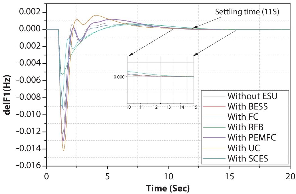
Figure 4.15a delF1 comparison of with/without ESU.
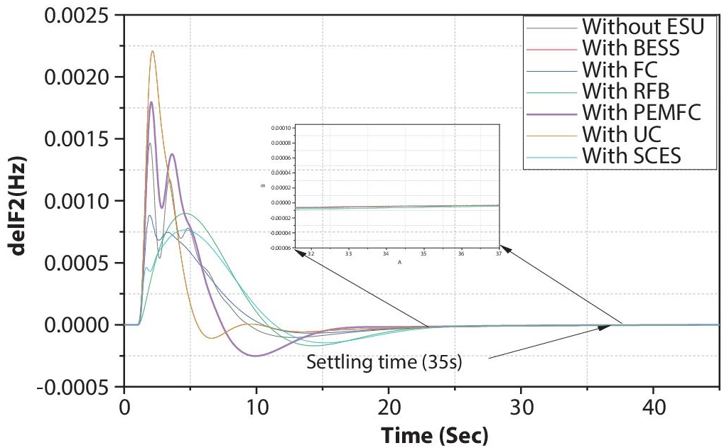
Figure 4.15b delF2 comparison of with/without ESU.
Bar chart in Figure 4.15d clearly demonstrates that the PEM – FC provides superior impact and support to the proposed optimization technique tuned controller for the LFC.

Figure 4.15c Assessment of tie line power deviation with/without ESU.
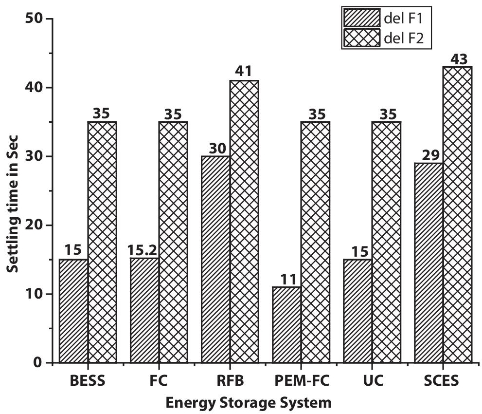
Figure 4.15d Bar chart comparison of the settling time of various ESUs.
4.7 Conclusion
In this chapter, the impact of ESU for implementing the LFM of interconnected nuclear power plants is studied. To implement the LFC in the proposed power system (an interconnected nuclear power plant), ACO tuned PID controller utilized as secondary controller. The energy storage units are utilized as small power sources, and the impact is analyzed in detail. Among various energy storage units (BESS, FC, RFB, PEM-FC, UC, SCES), the proton exchange membrane (PEM) based FC is more supported by the proposed optimization technique-based controller. While incorporating the PEM-FC in the proposed power system the secondary controller settles the oscillation in the frequency (F1 = (PEM-FC)11s < (BESS)15s < (FC)15.2s < (UC)15s < (SCES)29s < (RFB)30s) and (F2 = (PEM-FC = RFB = UC = BESS)35s < (RFB) 41s < (SCES) 43s) and also provide minimal peak values.
Challenges of energy storage units in power system
- The energy storage technology is one of the encouraging technologies in the application of renewable energy-based energy generation, distributed generation, microgrid, and smart grid. The energy storage unit’s implementation has two major challenges; one is technology based and the other is economically based.
- The implementation of the energy storage units has some limitations like power capacity, the lifespan of unit, economic, and security.
- In the economic aspect, high cost and an unhealthy market are the major factors when implementing the energy storage units in the power system.
Future scope of energy storage units in the power system
- The future of electricity mostly depends on renewable energy sources. Most renewable energy sources produce the non-linear power output. The non-linear power may create fluctuation in the power supply.
- To control the fluctuations, energy storage units are the most needed.
- In the future, the power grid may be replaced by a small decentralized or microgrid power system. In discussions about the microgrid, the energy storage units play a major role.
Appendix
TBESS = 0.1s, TFC = 0.26s, Ti/c = 0.004s, Tinv = 0.04s, Tdi = 1s, Tri = 0.78s, T1 = 0.28s, T2 = 0.025s, T3 = 0.04s, T4 = 0.39s, Ksc = 0.5 P.U, Tsc = 0.046, KUC = 0.7 P.U, TUC = 0.9s.
References
- 1. Sahu, P.C., Mishra, S., Prusty, R.C. and Panda, S., 2018. Improved-salp swarm optimized type-II fuzzy controller in load frequency control of multi area islanded AC microgrid. Sustainable Energy, Grids and Networks, 16, pp. 380-392.
- 2. Akram, U., Nadarajah, M., Shah, R. and Milano, F., 2020. A review on rapid responsive energy storage technologies for frequency regulation in modern power systems. Renewable and Sustainable Energy Reviews, 120, p. 109626.
- 3. Yildirim, B., 2021. Advanced controller design based on gain and phase margin for microgrid containing PV/WTG/Fuel cell/Electrolyzer/BESS. International Journal of Hydrogen Energy, 46(30), pp. 16481-16493.
- 4. Sharma, M., Bansal, R.K., Prakash, S. and Asefi, S., 2021. MVO algorithm based LFC design of a six-area hybrid diverse power system integrating IPFC and RFB. IETE Journal of Research, 67(3), pp. 394-407.
- 5. Mudi, J., Shiva, C.K., Vedik, B. and Mukherjee, V., 2021. Frequency stabilization of solar thermal-photovoltaic hybrid renewable power generation using energy storage devices. Iranian Journal of Science and Technology, Transactions of Electrical Engineering, 45(2), pp. 597-617.
- 6. Dhanasekaran, B., Siddhan, S. and Kaliannan, J., 2020. Ant colony optimization technique tuned controller for frequency regulation of single area nuclear power generating system. Microprocessors and Microsystems, 73, p. 102953.
- 7. Shankar, R., Chatterjee, K. and Bhushan, R., 2016. Impact of energy storage system on load frequency control for diverse sources of interconnected power system in deregulated power environment. International Journal of Electrical Power & Energy Systems, 79, pp. 11-26.
- 8. Xu, D., Liu, J., Yan, X.G. and Yan, W., 2017. A novel adaptive neural network constrained control for a multi-area interconnected power system with hybrid energy storage. IEEE Transactions on Industrial Electronics, 65(8), pp. 6625-6634.
- 9. Boopathi, D., Jagatheesan, K., Anand, B., Kumarakrishnan, V. and Samanta, S., 2022. Effect of Sustainable Energy Sources for Load Frequency Control (LFC) of Single-Area Wind Power Systems. In Industrial Transformation (pp. 87-98). CRC Press.
- 10. Sadoudi, S., Boudour, M. and Kouba, N.E.Y., 2021. Multi‐microgrid intelligent load shedding for optimal power management and coordinated control with energy storage systems. International Journal of Energy Research.
- 11. Ali, M., Parwanti, A. and Cahyono, I., 2018, October. Comparison of LFC Optimization on Micro-hydro using PID, CES, and SMES based Firefly Algorithm. In 2018 5th International Conference on Electrical Engineering, Computer Science and Informatics (EECSI) (pp. 204-209). IEEE.
- 12. Zhou, X., Dong, C., Fang, J. and Tang, Y., 2017, October. Enhancement of load frequency control by using a hybrid energy storage system. In 2017 Asian Conference on Energy, Power and Transportation Electrification (ACEPT) (pp. 1-6). IEEE.
- 13. Abazari, A., Monsef, H. and Wu, B., 2019. Coordination strategies of distributed energy resources including FESS, DEG, FC and WTG in load frequency control (LFC) scheme of hybrid isolated micro-grid. International Journal of Electrical Power & Energy Systems, 109, pp. 535-547.
- 14. Khadanga, R.K. and Kumar, A., 2019. Analysis of PID controller for the load frequency control of static synchronous series compensator and capacitive energy storage source-based multi-area multi-source interconnected power system with HVDC link. International Journal of Bio-Inspired Computation, 13(2), pp. 131-139.
- 15. Arya, Y., 2019. AGC of PV-thermal and hydro-thermal power systems using CES and a new multi-stage FPIDF-(1+ PI) controller. Renewable Energy, 134, pp. 796-806.
- 16. Ali, M., Djalal, M.R., Fakhrurozi, M. and Ajiatmo, D., 2018, October. Optimal Design Capacitive Energy Storage (CES) for Load Frequency Control in Micro Hydro Power Plant Using Flower Pollination Algorithm. In 2018 Electrical Power, Electronics, Communications, Controls and Informatics Seminar (EECCIS) (pp. 21-26). IEEE.
- 17. Sharma, R.K. and Mishra, S., 2017. Dynamic power management and control of a PV PEM fuel-cell-based standalone ac/dc microgrid using hybrid energy storage. IEEE Transactions on Industry Applications, 54(1), pp. 526-538.
- 18. Jagatheesan, K., Anand, B., Dey, N. and Ebrahim, M.A., 2016. Design of proportional-integral-derivative controller using stochastic particle swarm optimization technique for single-area AGC including SMES and RFB units. In Proceedings of the Second International Conference on Computer and Communication Technologies (pp. 299-309). Springer, New Delhi.
- 19. Jagatheesan, K., Anand, B., Dey, N. and Ashour, A.S., 2018. Effect of SMES unit in AGC of an interconnected multi-area thermal power system with ACO-tuned PID controller. In Advancements in Applied Metaheuristic Computing (pp. 164-184). IGI Global.
- 20. Boopathi, D., Saravanan, S., Jagatheesan, K. and Anand, B., 2021. Performance Estimation of Frequency Regulation for a Micro-Grid Power System Using PSO-PID Controller. International Journal of Applied Evolutionary Computation (IJAEC), 12(2), pp. 36-49.
- 21. Kumarakrishnan, V., Vijayakumar, G., Boopathi, D., Jagatheesan, K., Saravanan, S. and Anand, B., 2020. Optimized PSO Technique Based PID Controller for Load Frequency Control of Single Area Power System. Solid State Technology, 63(5), pp. 7979-7990.
- 22. Dhundhara, S. and Verma, Y.P., 2018. Capacitive energy storage with optimized controller for frequency regulation in realistic multisource deregulated power system. Energy, 147, pp. 1108-1128.
- 23. Jin, T.H., Chung, M., Shin, K.Y., Park, H. and Lim, G.P., 2016. Real-time dynamic simulation of korean power grid for frequency regulation control by MW battery energy storage system. Journal of Sustainable Development of Energy, Water and Environment Systems, 4(4), pp. 392-407.
- 24. Kouba, N.E.Y., Menaa, M., Hasni, M. and Boudour, M., 2016. A novel optimal frequency control strategy for an isolated wind–diesel hybrid system with energy storage devices. Wind Engineering, 40(6), pp. 497-517.
- 25. Kumar, R. and Sharma, V.K., 2020. Whale optimization controller for load frequency control of a two-area multi-source deregulated power system. International Journal of Fuzzy Systems, 22(1), pp. 122-137.
Note
- *Corresponding author: [email protected]