
Chapter 2
Working with Mains Voltage
In This Chapter
![]() Examining how mains-voltage wiring works
Examining how mains-voltage wiring works
![]() Making safe connections with mains-voltage circuits
Making safe connections with mains-voltage circuits
Mains voltage is the voltage that’s available in standard residential or commercial wall outlets. In the UK, this voltage is supposed to be around 230 VAC (volts, alternating current), since harmonisaiton with other European countries. Mains voltage used to be 240 VAC in the UK and, in some places, it still is. In fact, mains supply voltages do vary a bit in practice but they will generally be around 230-240 VAC, and we refer to it as 230 VAC in this book. In other parts of the world, the voltage is often lower or occasionally higher.
In the US, mains voltage is often called line voltage.
 Unlike the voltage available from household batteries, mains voltage is dangerous: if you’re not careful, it can kill you. So, avoid connecting your circuits directly to the mains voltage and use an adaptor to step down voltages for your circuits instead.
In this chapter, you learn about ways to use the mains supply safely so that neither you nor anyone else gets hurt.
Adapting the Mains Supply for Use in Your Projects
Although batteries are a convenient source of power for your circuits, the fact is that they wear out and have to be replaced. For certain real-world projects, however, you require a power source that lasts indefinitely. In these cases you need to use mains voltage and an adaptor, which allows you to plug the project in and not have to worry about changing batteries.
Of course, most electronic components require direct current (DC) rather than AC, and at much lower voltage levels than those that mains voltage supplies. Thus, for your project to use mains voltage as its source of power, you need to provide the project with a power supply that converts the 230 VAC mains voltage to something more useful, such as 5 VDC.
 You can fulfil this requirement in two basic ways:
![]() Use a power adapter: The easiest way is to use an external power adapter (often called a wall wart or a power brick). Figure 2-1 shows a typical external power adapter. You can purchase power adapters from just about any shop with a consumer electronics department. Just get one that provides the right level of DC voltage and use it instead of batteries.
Use a power adapter: The easiest way is to use an external power adapter (often called a wall wart or a power brick). Figure 2-1 shows a typical external power adapter. You can purchase power adapters from just about any shop with a consumer electronics department. Just get one that provides the right level of DC voltage and use it instead of batteries.

Figure 2-1: An external power adapter.
![]() Buy a mains power supply unit (PSU) module: The alternative to purchasing a power adapter is to buy a ready-made PSU module that goes in the box with your project’s circuit rather than sticking out of the wall socket. You connect it to the mains in a similar way to wiring a plug - follow the instructions that come with it and be careful, because even wiring a plug requires caution to stay safe. This circuit does two things:
Buy a mains power supply unit (PSU) module: The alternative to purchasing a power adapter is to buy a ready-made PSU module that goes in the box with your project’s circuit rather than sticking out of the wall socket. You connect it to the mains in a similar way to wiring a plug - follow the instructions that come with it and be careful, because even wiring a plug requires caution to stay safe. This circuit does two things:
It steps down the voltage from 230 VAC to whatever voltage your circuit requires.
It converts the AC voltage to DC voltage.
 You learn how a power-supply circuit works in Chapter 3 of this minibook, but buying a ready-made power adaptor is easier, much safer and usually cheaper.
Another common reason for using mains voltage in a project is if it needs to control an external device that runs on mains voltage, such as a flood lamp. In that case, your project has to be able to turn the mains voltage on and off.
The most common way to turn a mains voltage device on and off from an electronic circuit is to use a device called a relay, which is basically an electronic switch that uses a low-voltage input to control a high-voltage output. For example, a relay can let you use a 12 VDC circuit to control a separate mains-voltage circuit. We describe how to use a relay for this purpose later in this chapter in ‘Controlling mains-voltage circuits using relays’.
Staying safe with mains voltage
Whenever you build an electronics project that uses mains voltage, you must take extra precautions to ensure your safety and the safety of anyone who may come in contact with your project. Mains voltage is potentially deadly, and so these precautions are absolutely mandatory.
Mains voltage of 230 VAC is more than enough voltage to kill, given the right conditions. In fact, treat any voltage above 50 V as potentially lethal.
When you work with mains voltage, be sure to take the following precautions:
![]() Never let children work with mains, and if you’re under 16 years of age, this means you!
Never let children work with mains, and if you’re under 16 years of age, this means you!
![]() Never work on the circuit when the power plug is plugged in. This includes probing the circuit or making measurements with a multimeter or oscilloscope. These devices aren’t always designed with the levels of isolation from the mains voltage needed to keep you safe. And it’s all too easy to slip when probing a circuit and accidentally touch the live circuit.
Never work on the circuit when the power plug is plugged in. This includes probing the circuit or making measurements with a multimeter or oscilloscope. These devices aren’t always designed with the levels of isolation from the mains voltage needed to keep you safe. And it’s all too easy to slip when probing a circuit and accidentally touch the live circuit.
![]() Never leave exposed mains-voltage connections anywhere that you or anyone who comes into contact with your project may accidentally touch. All mains-voltage connections must be completely insulated or contained within an insulated project box.
Never leave exposed mains-voltage connections anywhere that you or anyone who comes into contact with your project may accidentally touch. All mains-voltage connections must be completely insulated or contained within an insulated project box.
![]() Always enclose projects that use mains voltage in a sealed project box so that stray hands can’t accidentally come in contact with bare wires or other components.
Always enclose projects that use mains voltage in a sealed project box so that stray hands can’t accidentally come in contact with bare wires or other components.
![]() Always use 3-core grounded power cords if your project is contained in a metal box, and always connect the metal box itself to the power cord’s earth ground lead. Also, always use 3-core wire if an insulated project box passes mains onto other devices outside the box.
Always use 3-core grounded power cords if your project is contained in a metal box, and always connect the metal box itself to the power cord’s earth ground lead. Also, always use 3-core wire if an insulated project box passes mains onto other devices outside the box.
![]() Always use the correct gauge of wire for the amount of current your circuit is carrying. For more information, see the later section, ‘Working Safely with Mains Voltage’.
Always use the correct gauge of wire for the amount of current your circuit is carrying. For more information, see the later section, ‘Working Safely with Mains Voltage’.
![]() Always ensure that all mains-voltage connections are tight and secure. When using stranded wire, always check for stray strands at your connections. Do not use solid wire as it can fracture and cause a short in places where it has been stripped back to connect to terminals.
Always ensure that all mains-voltage connections are tight and secure. When using stranded wire, always check for stray strands at your connections. Do not use solid wire as it can fracture and cause a short in places where it has been stripped back to connect to terminals.
![]() Always interconnect mains wiring using terminal blocks rated for UK mains use. Never be tempted to twist and/or solder the wires together.
Always interconnect mains wiring using terminal blocks rated for UK mains use. Never be tempted to twist and/or solder the wires together.
![]() Always provide some form of strain-relief for wires that carry mains voltage. The most common way to do so is to pass the wire through a grommet-protected hole in the project box. The wire cord must firmly secured to stop it pushing further inside the box and shorting to something it shouldn’t, as well as coming loose and pulling out of the box.
Always provide some form of strain-relief for wires that carry mains voltage. The most common way to do so is to pass the wire through a grommet-protected hole in the project box. The wire cord must firmly secured to stop it pushing further inside the box and shorting to something it shouldn’t, as well as coming loose and pulling out of the box.
![]() Always incorporate a fuse in the primary side of your mains-voltage circuit. The fuse automatically detects when too much current is flowing and immediately breaks the circuit. (For more on fuses, see the section ‘Protecting mains-voltage circuits with fuses’, later in this chapter.)
Always incorporate a fuse in the primary side of your mains-voltage circuit. The fuse automatically detects when too much current is flowing and immediately breaks the circuit. (For more on fuses, see the section ‘Protecting mains-voltage circuits with fuses’, later in this chapter.)
![]() Always use stranded mains wire and label the wires with the standard brown for live, blue for neutral and green/yellow for earth colour scheme to make it obvious which wire is which.
Always use stranded mains wire and label the wires with the standard brown for live, blue for neutral and green/yellow for earth colour scheme to make it obvious which wire is which.
![]() Never use a fuse that’s rated for more than the maximum current your circuit is designed to bear. For example, if you’re using a relay that can switch 5 amps (A) of current, use a fuse rated for 5 A or less.
Never use a fuse that’s rated for more than the maximum current your circuit is designed to bear. For example, if you’re using a relay that can switch 5 amps (A) of current, use a fuse rated for 5 A or less.
![]() Never arrange the wiring for your project in a way that causes wires to move or rub against one another. The rubbing eventually wears off the insulation and creates a shock hazard. Use cable ties to secure the wiring inside the enclosure.
Never arrange the wiring for your project in a way that causes wires to move or rub against one another. The rubbing eventually wears off the insulation and creates a shock hazard. Use cable ties to secure the wiring inside the enclosure.
![]() Always be aware of heat sinks (pieces of metal that help dissipate heat) that may be hot.
Always be aware of heat sinks (pieces of metal that help dissipate heat) that may be hot.
![]() Never become complacent. Always stay as careful as the day you started.
Never become complacent. Always stay as careful as the day you started.
Understanding live, neutral and earth
This section provides you with an introduction to how most residential and commercial buildings are wired. It does not provide enough information for you to attempt your own wiring, however, and you should always use a qualified professional electrician for this, anyway.
The following description applies only to the UK; if you’re in a different country, make sure that you determine the standards for your country’s wiring.
Standard mains-voltage wiring in the UK is done with plastic-sheathed cables, which usually have three conductors, as shown in Figure 2-2. This type of cable is called T&E cable, short for Twin and Earth cable and sometimes called Flat Twin and Earth.

Figure 2-2: T&E cabling.
Two of the conductors in T&E cable are covered with plastic insulation. In new installations one wire is blue (neutral) and the other brown (live), though most houses still have the old black and red wiring colours in use before the UK harmonised with Europe in 2006. The third conductor is bare copper within T&E cable. The conductors are designated as follows:
![]() Live: The brown wire in new installations is the live wire, which provides a 230 VAC source. In the older colour scheme in use before 2006, the live wire was red.
Live: The brown wire in new installations is the live wire, which provides a 230 VAC source. In the older colour scheme in use before 2006, the live wire was red.
![]() Neutral: The blue wire is called the neutral wire. It provides the return path for the current provided by the live wire. The neutral wire is connected to an earth ground. In the older colour scheme before 2006, the neutral wire was black. This does not mean the neutral wire is the same potential as the earth wire. And although it is grounded, you should treat it with as much respect as the live wire. The two could also be swapped and you wouldn’t necessarily know.
Neutral: The blue wire is called the neutral wire. It provides the return path for the current provided by the live wire. The neutral wire is connected to an earth ground. In the older colour scheme before 2006, the neutral wire was black. This does not mean the neutral wire is the same potential as the earth wire. And although it is grounded, you should treat it with as much respect as the live wire. The two could also be swapped and you wouldn’t necessarily know.
![]() Earth: The bare wire in T&E cable is called the earth wire. Like the neutral wire, the earth wire is also connected to an earth ground. However, the neutral and earth wires serve two distinct purposes. The neutral wire forms part of the live circuit along with the live wire, whereas the earth wire is connected to any metal parts in an appliance such as a microwave oven or coffee pot. This safety feature ensures that if the live or neutral wires somehow come in contact with metal parts, the fact that the metal parts are connected to earth ground eliminates the shock hazard in the event of a short circuit. Outside the T&E cable, the earth wire is sometimes sheathed with green and yellow bi-coloured plastic.
Earth: The bare wire in T&E cable is called the earth wire. Like the neutral wire, the earth wire is also connected to an earth ground. However, the neutral and earth wires serve two distinct purposes. The neutral wire forms part of the live circuit along with the live wire, whereas the earth wire is connected to any metal parts in an appliance such as a microwave oven or coffee pot. This safety feature ensures that if the live or neutral wires somehow come in contact with metal parts, the fact that the metal parts are connected to earth ground eliminates the shock hazard in the event of a short circuit. Outside the T&E cable, the earth wire is sometimes sheathed with green and yellow bi-coloured plastic.
Note that some circuits require a fourth conductor. When a fourth conductor is used, it’s covered with black insulation and is also a live wire.
The three wires in a standard T&E cable are connected to the three prongs of a standard electrical outlet as shown in Figure 2-3. As you can see, the neutral and live wires are connected to the two vertical prongs at the bottom of the socket (neutral on the left, live on the right) and the earth wire is connected to the prong at the top of the socket.

Figure 2-3: A standard UK electrical socket.
Always place switches or fuses on the live wire rather than on the neutral wire. That way, if the switch is open or the fuse blows, the current in the live wire is prevented from proceeding beyond the switch or fuse into your circuit. This approach minimises any risk of shock that may occur if a wire comes loose within your project.
Working Safely with Mains Voltage
In this section, we discuss safe wiring and connections, and describe the roles that fuses and relays play in mains-voltage circuits.
Wiring and connecting
When working with mains voltage, you must always use stranded wire (with standard brown, blue and green/yellow insulation colours) that’s designed specifically to handle mains-voltage currents.
When choosing wire, make sure that you select the right gauge for the current your circuit is going to be carrying. For circuits that are designed to carry up to 13 A, 1.3 mm diameter wire is sufficient. For less than 10 A, 1 mm diameter wire is sufficient.
Always buy your electrical parts from a reputable and reliable dealer. Many unsafe electrical components exist on the black market in the UK. They may well be improperly constructed, have not passed the required British standards or fail to meet UK wiring regulations. They may be cheaper, but they’re also illegal and potentially dangerous. Make sure legal parts are also suitable for UK mains usage too - component distributors sometimes stock others.
Make sure that all connections you make with wires carrying mains voltage are secure. The easiest way to connect the wires is to use a terminal block (also known as a barrier strip). Terminal blocks come in various sizes and shapes.
To use a terminal block, simply strip away a short length of insulation from the end of the wires you want to connect, insert them into each end of the terminal block and tighten the screws on top to clamp the wires in place. If you’re using stranded wire, make sure that the screw is holding all the strands, because loose strands can cause short circuits.
Protecting mains-voltage circuits with fuses
A fuse is an inexpensive device that can carry only a certain amount of current. If the current exceeds the rated level, the fuse melts (blows), thus breaking the circuit and preventing the excessive current from flowing. Fuses are an essential component of any electrical system that uses mains voltage and has the possibility of short-circuiting or overheating and causing a fire.
The most common type of fuse is the cartridge fuse, which consists of a cylindrical body that’s usually made of glass, plastic or ceramic and has two metal ends (see Figure 2-4). These metal ends are the two terminals of the fuse. Inside the body is a thin wire conductor that’s designed to melt away if the current exceeds the rated threshold. As long as the current stays below the maximum level, the conductor passes the current from one metal end to the other. But when the current exceeds the rated maximum, the conductor melts and the circuit is broken.
Maplin (www.maplin.co.uk/components/fuses) sells fuses and sets of fuses with various current ratings. Use fast blow types or standard mains plug fuses.
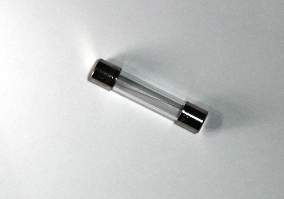
Figure 2-4: A 2 A fuse.
Always connect the fuse to the live wire and place it before any other component in the circuit. In most projects, the fuse should be the first thing the live wire connects to after it enters your project enclosure. Figure 2-5 shows how a fuse is depicted in a schematic diagram. Here, the fuse is placed on the live wire before the lamp.

Figure 2-5: A fuse in a schematic diagram.
If you plan on using a fuse in your circuit, you need to purchase a fuse holder to contain it. If the fuse is to be mounted inside your project’s enclosure, you can use a chassis-type fuse holder. If you want the fuse to be accessible from outside the project’s enclosure, choose a panel-mount holder instead. Figure 2-6 shows a panel-mount holder. Component suppliers such as Maplin sell parts that combine externally accessible fuse holders with power-input sockets and on/off switches.
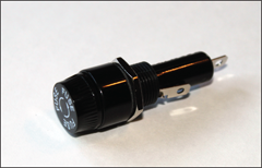
Figure 2-6: A panel-mount holder.
Controlling mains-voltage circuits using relays
In many projects, you need to turn mains-voltage circuits on and off using circuits that use low-voltage DC power supplies. For example, suppose that you want to flash a 230 VAC flood lamp on and off at regular intervals. You can build a circuit to provide the necessary timing using a 555 timer IC (as we describe in Book III, Chapter 2), but this integrated circuit requires just a small DC power supply, in the range of 5 to 15 V. Plus the output current can’t exceed 200 milliamperes (mA), which isn’t nearly enough to light a flood lamp.
But never fear, because in this case it’s relays to the rescue!
A relay is an electromechanical device that uses an electromagnet to open or close a switch. The circuit that powers the electromagnet’s coil is completely separate from the circuit that’s switched on or off by the relay’s switch, and so you can use a relay whose coil requires just a few volts to turn a mains-voltage circuit on or off.
Figure 2-7 shows a typical relay. For this one, the coil requires just 12 VDC to operate and pulls just 75 mA, well under the current limit that can be sourced by the 555 timer IC’s output pin. But the switch part of this relay can handle up to 10 A of current at 230 VAC, which is more than enough to illuminate a flood lamp.

Figure 2-7: A relay is a switch that’s controlled by an electromagnet.
The switch part of a relay is available in different configurations just like manual switches. The most common switch configuration is double pole, double throw (DPDT), which means that the relay controls two separate switches that operate together and each switch has normally open and normally closed contacts. However, the circuits in Figures 2-8 and 2-9 use simple single pole, double throw (SPDT) relays to switch simple powered circuits on or off. To find out more about switches, check out Book II, Chapter 1.
Figure 2-8 shows a schematic diagram for a simple circuit that uses a 9 VDC circuit with a handheld pushbutton to turn a 230 VAC lamp on and off. The relay in the circuit has a coil rated for 9 VDC and a switch rating of 5 A at 230 VAC. Thus, only 9 VDC passes through the pushbutton. If you’re holding the switch and decide to take it apart, you aren’t exposed to dangerous voltage.

Figure 2-8: Using a relay to switch a mains-voltage circuit.
Figure 2-9 shows a more complicated circuit, in which a 555 timer IC controls a flood lamp via a relay. One end of the relay coil is connected to the 555 timer IC’s output pin (pin 3) and the other end is connected to ground. When the 555’s output switches on, the relay closes and the flood lamp circuit is completed.
Note the diode that’s placed across the relay coil in this circuit. This diode is required to protect the 555 timer IC from any back-current that may be created within the relay’s coil when the coil is energised. Because of electromagnetic induction, relay coils are prone to this problem.

Figure 2-9: Driving a relay from a 555 timer IC.
When the coil is energised, it creates a magnetic field that causes the relay’s switch contacts to move. However, this magnetic field has a subtle side effect. In the instant that the voltage on the coil goes from zero to the Vss supply voltage, the magnetic field surrounding the coil expands from nothing to its maximum strength. During this expansion, the magnetic field is moving relative to the coil itself. The principle of induction means that this moving magnetic field induces a current in the coil itself, in the opposite direction to the current that’s energising the coil.
Depending on the circumstances, this back-current can be powerful enough to overwhelm the output current coming from the 555 timer IC and possibly powerful enough to send current into the output pin, which can damage or destroy the 555 chip. The diode D1 prevents this from happening by providing the equivalent of a short circuit across the coil for current flowing back towards the output pin.
Whenever you drive a relay from a circuit that has delicate components such as integrated circuits or transistors, always include a diode across the relay coil to prevent the relay from damaging your circuits.