
Chapter 3
Working with Capacitors
In This Chapter
![]() Mining the mysteries of capacitors
Mining the mysteries of capacitors
![]() Measuring capacitors
Measuring capacitors
![]() Calculating important capacitor numbers
Calculating important capacitor numbers
![]() Building some basic capacitor circuits
Building some basic capacitor circuits
In the film Back to the Future, Doc Brown’s famous flux capacitor can convert 1.21 gigawatts of power into a distortion in the space-time continuum, which allows him to send his friend Marty McFly back to 1955 and change the course of history.
The flux capacitor is science fiction. But capacitors are real and they did change the course of history, because you find them in almost every electronic circuit, including those that you build.
What Is a Capacitor?
To begin understanding what a capacitor is, consider this question: what makes current flow within a conductor? In Book I, Chapter 2, we explain that opposite charges attract one another and like charges repel one another. The attraction or repulsion is caused by a force known as the electromagnetic force. All charged particles exhibit an electric field that’s associated with this force. This field is what draws electrons (negative charges) towards protons (positive charges) and also what pushes electrons away from one another.
 Within a conductor such as copper, the electric fields produced by individual electrons create a constant movement of electrons within the conductor. However, this movement is completely random. When voltage is applied across the two ends of a conductor, an electric field is created, which causes the movement of electrons to become organised. The electric field pushes electrons through the conductor in an orderly fashion from the negative side of the voltage to the positive side. The result is current.
Unlike current, an electric field doesn’t need a conductor to travel. An electric field can reach right across an insulator (see Book 1, Chapter 1) and push away or tug on charges on the other side of the insulator.
This ability may look like magic, but you’ve encountered it before. Blow up a balloon, rub it quickly against your shirt and then hold it up to your hair. Rubbing the balloon creates a static charge in the balloon. When this charge comes close to your hair, its electric field tugs the charges in your hair, which is drawn up towards the balloon.
Catching up with capacitors
A capacitor (or sometimes simply a cap) is an electronic component that takes advantage of the apparently magical ability of electric fields to reach out across an insulator. It consists of two flat plates made from a conducting material such as silver or aluminium, separated by a thin insulating material such as Mylar or ceramic, as shown in Figure 3-1. The two conducting plates are connected to terminals so that a voltage can be applied across the plates.

Figure 3-1: A capacitor creates an electric field between two charged plates separated by an insulator.
Note that because an insulator separates the two plates, a closed circuit isn’t formed. Nevertheless, current flows – for a moment, anyway.
How can this be? When the voltage from a source such as a battery is connected, the negative side of the battery voltage immediately begins to push negative charges towards one of the plates. Simultaneously, the positive side of the battery voltage begins to pull electrons (negative charges) away from the second plate.
The electric field that quickly builds up between the two plates permits current to flow. As the plate on the negative side of the circuit fills with electrons, the electric field created by those electrons begins to push electrons away from the plate on the other side of the insulator, towards the positive side of the battery voltage.
As this current flows, the negative plate of the capacitor builds up an excess of electrons, whereas the positive side develops a corresponding deficiency of electrons. Thus, voltage is developed between the two plates of the capacitor. (Remember, the definition of voltage is the difference of charge between two points.)
The catch is that this current flows only for a brief time. As the electrons build up on the negative plate and are depleted from the positive plate, the voltage between the two plates increases because the difference in charge between the two plates increases. The voltage continues to increase until the capacitor voltage equals the battery voltage. When the voltages are the same, current stops flowing through the circuit, and the capacitor is said to be charged.
At this point the magic gets even better. After a capacitor has been charged, you can disconnect the battery from the capacitor and the charge remains in the capacitor. In other words, although the battery creates the voltage in the capacitor, this voltage isn’t dependent on the battery for its continued existence. Disconnect the battery and the voltage remains across the two plates of the capacitor.
Therefore, capacitors have the ability to store charge – an ability known as capacitance.
If a charged capacitor is connected to a circuit, the voltage across the plates drives current through the circuit, which is called discharging the capacitor. Just as the current that charges a capacitor lasts for only a short time, the current that results when a capacitor discharges also lasts for only a short time. As the capacitor discharges, the charge difference between the two plates decreases and the electric field collapses. When the two plates reach equilibrium, the voltage across the plates reaches zero and no current flows.
 Charged or not charged?
From a pure physics standpoint, saying that a capacitor has the ability to store charge isn’t quite accurate. What a capacitor actually stores is energy in the form of an electric field that creates a voltage across the two plates. Strictly speaking, the capacitor doesn’t have any more charge in it when fully ‘charged’ than when it isn’t.
The difference is that when a capacitor isn’t charged, the total negative and positive charges of the capacitor are divided evenly between the plates, and so no voltage exists across the plates. In contrast, when a capacitor is charged, the negative charges are concentrated on one plate and the positive charges on the other plate. The total amount of charge in the capacitor is the same either way.
By the way (for bonus points), the insulating material between the two conducting plates is called dielectric. This term refers to the ability of the insulating layer to become polarised by the electric field that exists between the two plates when they become charged.
Knowing the capacitor symbols
Here are some of the capacitor symbols you encounter in schematic diagrams:
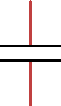
![]() The most common symbol is simply two parallel lines separated by a gap, as shown in the margin.
The most common symbol is simply two parallel lines separated by a gap, as shown in the margin.

![]() An alternative symbol uses a straight line and a curved line to represent the plates. The curved line is generally used on the negative side of the circuit.
An alternative symbol uses a straight line and a curved line to represent the plates. The curved line is generally used on the negative side of the circuit.

![]() Although some capacitors aren’t sensitive to polarity, many others are. This sensitivity is connected to the choice of materials used to create the capacitors: with certain materials, connecting the voltage in the wrong direction can damage the capacitor. Capacitors with distinct positive and negative terminals are called polarised capacitors. A plus sign is used in the schematic diagram to indicate the polarity, as shown in the margin.
Although some capacitors aren’t sensitive to polarity, many others are. This sensitivity is connected to the choice of materials used to create the capacitors: with certain materials, connecting the voltage in the wrong direction can damage the capacitor. Capacitors with distinct positive and negative terminals are called polarised capacitors. A plus sign is used in the schematic diagram to indicate the polarity, as shown in the margin.
Counting Capacitance
Capacitance refers to the ability of a capacitor to store charge. It’s also the measurement used to indicate how much energy a particular capacitor can store. The more capacitance a capacitor has, the more charge it can store.
Finding out about farads
Capacitance is measured in units called farads (abbreviated F). The definition of 1 farad is deceptively simple. A 1-farad capacitor holds a voltage across the plates of exactly 1 V when it’s charged with exactly 1 ampere per second of current.
Note that ‘1 ampere per second of current’ refers to the amount of charge present in the capacitor. No rule states that the current has to flow for a full second. It can be 1 ampere for 1 second, or 2 amperes for half a second or half an ampere for 2 seconds. Or it can be 100 mA for 10 seconds or 10 mA for 100 seconds.
One ampere per second corresponds to the standard unit for measuring electric charge, called the coulomb. So another way of stating the value of 1 farad is to say that it’s the amount of capacitance that can store 1 coulomb with a voltage of 1 V across the plates.
One farad is a huge amount of capacitance, because 1 coulomb is a very large amount of charge. To put it into perspective, the total charge contained in an average lightning bolt is about 5 coulombs, and you need only five 1-farad capacitors to store the charge contained in a lightning strike. (Some lightning strikes are much more powerful, as much as 350 coulombs.)
Capacitors used in electronics are charged from much more modest sources than lightning bolts. In fact, the largest capacitors you’re likely to use have capacitance measured in millionths of a farad, called microfarads and abbreviated μF (the μ is the Greek letter mu, a common abbreviation for micro). Smaller capacitors are measured in millionths of a microfarad, called a picofarad and abbreviated pF.
 Values of 1,000 pF or more are commonly represented in μF rather than pF. For example, 1,000 pF is written as 0.001 μF and 22,000 pF is written as 0.022 μF.
Like resistors (which we discuss in Chapter 2 of this minibook), capacitors aren’t manufactured to perfection. Instead, most capacitors have a margin of error, also called tolerance. In some cases, the margin of error may be as much as 80%. Fortunately, that degree of imprecision rarely has a noticeable effect on most circuits.
Reading capacitor values
If enough room is available on the capacitor, most manufacturers print the capacitance directly on the capacitor along with other information such as the working voltage and perhaps the tolerance. Small capacitors don’t have enough room for all that, however, and so many manufacturers use a shorthand notation to indicate capacitance on small caps.
If you have a capacitor with nothing other than a three-digit number printed on it, the third digit represents the number of zeros to add to the end of the first two digits. The resulting number is the capacitance in pF. For example, 101 represents 100 pF: the digits 1 and 0 followed by one additional zero.
If only two digits are listed, the number is simply the capacitance in pF. Thus, the digits 22 indicate a 22 pF capacitor.
Table 3-1 lists how some common capacitor values are represented using this notation.
Table 3-1 Capacitance Markings
|
Marking |
Capacitance (pF) |
Capacitance (μF) |
|
101 |
100 |
0.0001 |
|
221 |
220 |
0.00022 |
|
471 |
470 |
0.00047 |
|
102 |
1,000 |
0.001 |
|
222 |
2,200 |
0.0022 |
|
472 |
4,700 |
0.0047 |
|
103 |
10,000 |
0.01 |
|
223 |
22,000 |
0.022 |
|
473 |
47,000 |
0.047 |
|
104 |
100,000 |
0.1 |
|
224 |
220,000 |
0.22 |
|
474 |
470,000 |
0.47 |
|
105 |
1,000,000 |
1 |
|
225 |
2,200,000 |
2.2 |
|
475 |
4,700,000 |
4.7 |
You may also see a letter printed on the capacitor to indicate the tolerance. You can interpret the tolerance letter according to Table 3-2.
Table 3-2 Capacitor Tolerance Markings
|
Letter |
Tolerance |
|
A |
±0.05 pF |
|
B |
±0.1 pF |
|
C |
±0.25 pF |
|
D |
±0.5 pF |
|
E |
±0.5% |
|
F |
±1% |
|
G |
±2% |
|
H |
±3% |
|
J |
±5 % |
|
K |
±10% |
|
L |
±15% |
|
M |
±20% |
|
N |
±30% |
|
P |
–0%, + 100% |
|
S |
–20%, + 50% |
|
W |
–0%, + 200% |
|
X |
–20%, + 40% |
|
Z |
–20%, + 80% |
Note that the tolerances for codes P to Z are a little odd:
![]() Codes P and W: The manufacturer promises that the capacitance is no less than the stated value, but may be as much as 100% or 200% over the stated value. For example, if the marking is 101P, the actual capacitance is no less than 100 pF but may be as much as 200 pF.
Codes P and W: The manufacturer promises that the capacitance is no less than the stated value, but may be as much as 100% or 200% over the stated value. For example, if the marking is 101P, the actual capacitance is no less than 100 pF but may be as much as 200 pF.
![]() Codes S, X and Z: The actual capacitance may be as much as 20% below the stated value or as much as 50%, 40% or 80% over the stated value. So, if the marking is 101Z, the capacitance is between 80 pF and 180 pF.
Codes S, X and Z: The actual capacitance may be as much as 20% below the stated value or as much as 50%, 40% or 80% over the stated value. So, if the marking is 101Z, the capacitance is between 80 pF and 180 pF.
Sizing Up Capacitors
Capacitors come in all sorts of shapes and sizes, influenced mostly by three things: the type of material used to create the plates, the type of material used for the dielectric (the insulating material between the two conducting plates) and the capacitance. Figure 3-2 shows some varieties of capacitors.

Figure 3-2: Capacitors are made in many different shapes and sizes.
The most common types of capacitors are as follows:
![]() Ceramic disc: The plates are made by coating both sides of a small ceramic or porcelain disc with silver solder. The ceramic or porcelain disc is the dielectric and the silver solder forms the plates. Leads are soldered to the plates, and the entire thing is dipped in resin.
Ceramic disc: The plates are made by coating both sides of a small ceramic or porcelain disc with silver solder. The ceramic or porcelain disc is the dielectric and the silver solder forms the plates. Leads are soldered to the plates, and the entire thing is dipped in resin.
Ceramic disc capacitors are small and usually have low capacitance values, ranging from 1 pF to a few microfarads. This small size means that their values are usually printed using the three-digit shorthand notation that we describe in the preceding section.
Ceramic disc capacitors aren’t polarised and so you don’t have to worry about polarity when using them.
![]() Electrolytic: One of the plates is made by coating a foil film with a highly conductive, semiliquid solution called electrolyte. The other plate is another foil film on which an extremely thin layer of oxide has been deposited; this thin layer serves as the dielectric. The two layers are then rolled up and enclosed in a metal can, epoxy or plastic.
Electrolytic: One of the plates is made by coating a foil film with a highly conductive, semiliquid solution called electrolyte. The other plate is another foil film on which an extremely thin layer of oxide has been deposited; this thin layer serves as the dielectric. The two layers are then rolled up and enclosed in a metal can, epoxy or plastic.
 Electrolytic capacitors are polarised, and so you have to be sure to connect voltage to them in the proper direction. If you apply voltage in the wrong direction, the capacitor may be damaged or even explode.
You find two common types of electrolytic capacitors:
• Aluminium: Can be quite large, with as much as a tenth of a farad or more (100,000 μF).
• Tantalum: Smaller and range up to about 1,000 μF.
![]() Film: The dielectric is made from a thin film-like sheet of insulating material and the plates are made from film-like sheets of metal foil. In some cases, the plates and the dielectric are then tightly rolled together and enclosed in a metal or plastic can. In other cases, the layers are stacked and then dipped in epoxy.
Film: The dielectric is made from a thin film-like sheet of insulating material and the plates are made from film-like sheets of metal foil. In some cases, the plates and the dielectric are then tightly rolled together and enclosed in a metal or plastic can. In other cases, the layers are stacked and then dipped in epoxy.
Depending on the materials used, capacitance for film capacitors can be as small as 1,000 pF or as large as 100 μF. Film capacitors aren’t polarised.
![]() Silver mica: The dielectric is made from mica, and this capacitor is sometimes referred to as a mica capacitor. As with ceramic capacitors, the plates in a silver mica capacitor are made from silver. Electrodes are joined to the plates and then the capacitor is dipped in epoxy.
Silver mica: The dielectric is made from mica, and this capacitor is sometimes referred to as a mica capacitor. As with ceramic capacitors, the plates in a silver mica capacitor are made from silver. Electrodes are joined to the plates and then the capacitor is dipped in epoxy.
Silver mica capacitors come in about the same capacitance range as ceramic disc capacitors. However, they can be made to much higher tolerances – as close as 1% in some cases. Like ceramic disc capacitors, silver mica capacitors aren’t polarised.
Although ceramic disc and mica capacitors are constructed in a similar way, they’re easy to tell apart. Ceramic disc capacitors are thin, flat discs and are nearly always a yellowish-brown or orange colour. Silver mica capacitors are thicker, bulge at the ends where the leads are attached, and are shiny and sometimes colourful – red, blue, yellow and green are common colours for mica capacitors. (Interestingly enough, we’ve never seen a silver silver mica capacitor, if you get what we mean!)
![]() Variable: A capacitor whose capacitance can be adjusted by turning a knob. One common use for a variable capacitor is to tune a radio circuit to a specific frequency.
Variable: A capacitor whose capacitance can be adjusted by turning a knob. One common use for a variable capacitor is to tune a radio circuit to a specific frequency.
In the most common type of variable capacitor, air is used as the dielectric and the plates are made of rigid metal. As shown in Figure 3-3, several pairs of plates are typically used in an intermeshed arrangement. One set of plates is fixed (not moveable), but the other set is attached to a rotating knob. When you turn the knob, you change the amount of surface area on the plates that overlap. This, in turn, changes the capacitance of the device.

Figure 3-3: A variable capacitor.
 The schematic symbol for a variable capacitor is shown in the margin.
Calculating Time Constants for Resistor/Capacitor Networks
As we mention earlier in the ‘What Is a Capacitor’ section, when you put a voltage across a capacitor, a bit of time is necessary for the capacitor to charge fully. During this period, current flows through the capacitor. Similarly, when you discharge a capacitor by placing a load across it, the capacitor takes time to discharge fully. Knowing exactly how much time charging a capacitor takes is one of the keys to using capacitors correctly in your circuits, and you can get that information by calculating the RC time constant.
Calculating the exact amount of time required to charge or discharge a capacitor requires more maths than we’re willing to throw at you in this book; simple algebra is one thing, but we draw the line at calculus! Fortunately, you can skip the calculus and use simple algebra if you’re willing to settle for close approximations. Given that most resistors and capacitors have a tolerance of plus or minus 5 or 10% anyway, using approximate calculations doesn’t have any significant effect on your circuits.
Looking at the calculations
Before making the approximate calculations, we need to emphasise the importance of understanding the concepts behind the calculus – even if you don’t do the calculus itself.
When a capacitor is charging, current flows from a voltage source through the capacitor. In most circuits, a resistor is working in series with the capacitor as well, as shown in Figure 3-4.
In fact, a circuit always has resistance even if you don’t use a resistor, because the perfect conductor doesn’t exist – even solid wire has some resistance. For the purposes of this discussion, assume that a resistor is in the circuit, but that its resistance may be 0 Ω.
![]()
Figure 3-4: A capacitor charging circuit.
The rate at which the capacitor charges through a resistor is called the RC time constant (the RC stands for resistor-capacitor), which you can calculate by multiplying the resistance in ohms by the capacitance in farads. Here’s the formula:
T = R × C
For example, suppose the resistance is 10 kΩ and the capacitance is 100 μF. Before you do the multiplication, you must first convert the μF to farads. One μF is one-millionth of a farad, and so you can convert μF to farads by dividing the μF by one million. Therefore, 100 μF is equivalent to 0.0001 F. Multiplying 10 kΩ by 0.0001 F gives you a time constant of 1 second.
If you want to increase the RC time constant, you can increase the resistance or the capacitance, or both. Also, you can use an infinite number of combinations of resistance and capacitance values to reach a desired RC time constant. For example, all the following combinations of resistance and capacitance yield a time constant of 1 second:
|
Resistance |
Capacitance |
RC Time Constant |
|
1 kΩ |
1,000 μF |
1 s |
|
10 kΩ |
100 μF |
1 s |
|
100 kΩ |
10 μF |
1 s |
|
1 MΩ |
1 μF |
1 s |
Appreciating the RC time constant
Importantly, in each interval of the RC time constant, the capacitor moves 63.2% closer to a full charge. For example, after the first interval, the capacitor voltage equals 63.2% of the battery voltage. So if the battery voltage is 9 V, the capacitor voltage is just under 6 V after the first interval, leaving it just over 3 V away from being fully charged.
In the second time interval, the capacitor picks up 63.2%, not of the full 9 V of battery voltage but 63.2% of the difference between the starting charge (just under 6 V) and the battery voltage (9 V). Thus, the capacitor charge picks up just over 2 additional volts, bringing it up to about 8 V.
This process keeps repeating: in each time interval, the capacitor picks up 63.2% of the difference between its starting voltage and the total voltage. In theory, the capacitor is never fully charged, because with the passing of each RC time constant it picks up only a percentage of the remaining available charge. But within just a few time constants, the capacitor becomes very close to fully charged (check out the nearby sidebar ‘Full charge ahead!’ for a little more detail).
Full charge ahead!
Although in theory a capacitor never becomes fully charged, in reality the capacitor does eventually become fully charged (say what!). The difference between theory and reality in this context is that in mathematics you can use as many digits beyond the decimal point as you want. In other words, no limit exists to how small a number can be. But a limit does exist to how small a charge can be: it can’t be smaller than a single electron.
When enough time constants have elapsed, the difference between the battery voltage and the capacitor charge is a single electron. When that electron joins the charge, the capacitor is full.
The following minitable gives you a helpful approximation of the percentage of charge that a capacitor reaches after the first five time constants. For all practical purposes, you can consider the capacitor fully charged after five time constants have elapsed.
|
RC Time Constant Interval |
Percentage of Total Charge |
|
1 |
63.2% |
|
2 |
86.5% |
|
3 |
95.0% |
|
4 |
98.2% |
|
5 |
99.3% |
Combining Capacitors
In Chapter 2 of this minibook, we explain how you can combine resistors in series or parallel networks to create any arbitrary resistance value you need. Well, you can do the same with capacitors. But as we discuss in this section, the formulas for calculating the total capacitance of a capacitor network are the reverse of the rules you follow to calculate resistor networks.
In other words, the formula you use for resistors in series applies to capacitors in parallel, and the formula you use for resistors in parallel applies to capacitors in series.
Combining capacitors in parallel
Calculating the total capacitance of two or more capacitors in parallel is simple: just add up the individual capacitor values to get the total capacitance. For example, if you combine three 100 μF capacitors in parallel, the total capacitance of the circuit is 300 μF.
This rule makes sense because when you connect capacitors in parallel, you’re essentially connecting the plates of the individual capacitors. Therefore, connecting two identical capacitors in parallel doubles the size of the plates, which effectively doubles the capacitance.
Figure 3-5 shows how parallel capacitors work. Here, the two circuits have identical capacitances. The right-hand circuit accomplishes the job with one capacitor and the left-hand one does it with three, but the circuits are equivalent.

Figure 3-5: Combining capacitors in parallel.
Whenever you see two or more capacitors in parallel in a circuit, you can substitute a single capacitor whose value is the sum of the individual capacitors. Similarly, any time you see a single capacitor in a circuit, you can substitute two or more capacitors in parallel as long as their values add up to the original value.
The total capacitance of capacitors in parallel is always greater than the capacitance of any of the individual capacitors, because each capacitor adds its own capacitance to the total.
Connecting capacitors in series
You can also combine capacitors in series to create equivalent capacitances, as shown in Figure 3-6. When you do, however, the maths is a little more complicated; the calculations required for capacitors in series are the same as for calculating resistors in parallel.

Figure 3-6: Combining capacitors in series.
Here are the rules for calculating capacitances in series:
![]() Capacitors of equal value in series: You’re in luck! All you have to do is divide the value of one of the individual capacitors by the number of capacitors. For example, the total capacitance of two 100 μF capacitors is 50 μF.
Capacitors of equal value in series: You’re in luck! All you have to do is divide the value of one of the individual capacitors by the number of capacitors. For example, the total capacitance of two 100 μF capacitors is 50 μF.
![]() Two capacitors of different values in series: Use this calculation (C1 and C2 are the values of the two capacitors):
Two capacitors of different values in series: Use this calculation (C1 and C2 are the values of the two capacitors):
![]()
Here’s an example, based on a 220 μF and a 470 μF capacitor in series:
![]()
![]() Three or more capacitors of different values in series: The formula is as follows:
Three or more capacitors of different values in series: The formula is as follows:
![]()
Note that the ellipsis at the end of the expression indicates that you keep adding up the reciprocals of the capacitances for as many capacitors as you have.
Here’s an example for three capacitors whose values are 100 μF, 220 μF and 470 μF:
![]()
As you can see, the final result is 59.977 μF. Unless your middle name is Pedantic, you probably don’t care about the answer being quite so precise, and so you can safely round it to an even 60 μF.
Putting Capacitors to Work
Capacitors can be incredibly useful in your circuits. Here are the most common ways to put capacitors to work:
![]() Storing energy: When charged, a capacitor has the ability to store a lot of energy and discharge it when needed (see Project 3-1 in the next section). Two of the most familiar uses of this ability are in a camera’s flash and in devices such as alarm clocks that need to stay powered up even when household power is disrupted for a few moments.
Storing energy: When charged, a capacitor has the ability to store a lot of energy and discharge it when needed (see Project 3-1 in the next section). Two of the most familiar uses of this ability are in a camera’s flash and in devices such as alarm clocks that need to stay powered up even when household power is disrupted for a few moments.
![]() Timing circuits: Many circuits depend on capacitors along with resistors to provide timing intervals. For example, in Chapter 6 of this minibook you discover how to use a resistor and capacitor together along with a transistor to create a circuit that flashes an LED on and off.
Timing circuits: Many circuits depend on capacitors along with resistors to provide timing intervals. For example, in Chapter 6 of this minibook you discover how to use a resistor and capacitor together along with a transistor to create a circuit that flashes an LED on and off.
![]() Stabilising shaky direct current (DC): Many electronic devices run on DC but derive their power from household alternating current (AC). These devices use a power-supply circuit that converts AC to DC. As we discuss in Book IV, Chapter 3, an important part of this circuit is a capacitor that creates steady DC voltage from the constantly changing voltage of an AC circuit.
Stabilising shaky direct current (DC): Many electronic devices run on DC but derive their power from household alternating current (AC). These devices use a power-supply circuit that converts AC to DC. As we discuss in Book IV, Chapter 3, an important part of this circuit is a capacitor that creates steady DC voltage from the constantly changing voltage of an AC circuit.
![]() Blocking DC while passing AC: Sometimes you need to prevent DC from flowing while allowing AC to pass. A capacitor can do this job for you. The basic trick is to choose a capacitor that fully charges and discharges within the AC cycle. Remember that as the capacitor is charging and discharging, it allows current to flow. So as long as you can keep the capacitor charging and discharging, it passes the current. Flip to Project 3-2 in the later section ‘Blocking DC while Passing AC’.
Blocking DC while passing AC: Sometimes you need to prevent DC from flowing while allowing AC to pass. A capacitor can do this job for you. The basic trick is to choose a capacitor that fully charges and discharges within the AC cycle. Remember that as the capacitor is charging and discharging, it allows current to flow. So as long as you can keep the capacitor charging and discharging, it passes the current. Flip to Project 3-2 in the later section ‘Blocking DC while Passing AC’.
![]() Filtering certain frequencies: Capacitors are often at work in audio or radio circuits to select certain frequencies. For example, a variable capacitor (check out the earlier section ‘Sizing Up Capacitors’) is often used in a radio circuit to tune the circuit to a certain frequency. You see how that works in Book V, Chapter 2.
Filtering certain frequencies: Capacitors are often at work in audio or radio circuits to select certain frequencies. For example, a variable capacitor (check out the earlier section ‘Sizing Up Capacitors’) is often used in a radio circuit to tune the circuit to a certain frequency. You see how that works in Book V, Chapter 2.
Charging and discharging a capacitor
One of the most common uses for capacitors is to store a charge that you can discharge when needed. Project 3-1 presents a simple construction project on a solderless breadboard that demonstrates how you can use a capacitor to this end. You connect an LED to a 3 V battery power supply and use a capacitor so that when you disconnect the battery from the circuit, the LED doesn’t immediately go out. Instead, it continues to glow for a moment as the capacitor discharges.
Figure 3-7 shows the completed project.

Figure 3-7: The capacitor discharge circuit.
Here are some additional points to consider or things you may want to try after you complete Project 3-1:
![]() Pull the LED out of the breadboard, and then close the switch to charge the capacitor. After a few seconds, open the switch. Then, use the voltmeter function of your multimeter to measure the voltage across the two leads of the capacitor. Notice that even though the battery is disconnected from the circuit, the capacitor reads 3 V.
Pull the LED out of the breadboard, and then close the switch to charge the capacitor. After a few seconds, open the switch. Then, use the voltmeter function of your multimeter to measure the voltage across the two leads of the capacitor. Notice that even though the battery is disconnected from the circuit, the capacitor reads 3 V.
![]() Try varying the size of the capacitor to see what happens. If you use a smaller capacitor, the LED extinguishes more quickly when you remove the power. If you use a larger capacitor, the LED fades more slowly.
Try varying the size of the capacitor to see what happens. If you use a smaller capacitor, the LED extinguishes more quickly when you remove the power. If you use a larger capacitor, the LED fades more slowly.
![]() You may not be able to find a capacitor larger than 1,000 μF, but you can increase the capacitance by adding more capacitors in parallel with the 1,000 μF capacitor.
You may not be able to find a capacitor larger than 1,000 μF, but you can increase the capacitance by adding more capacitors in parallel with the 1,000 μF capacitor.
![]() Try adding a resistor in series with the capacitor. To do that, simply replace the jumper wire you connect in Step 6 of Project 3-1 with a resistor.
Try adding a resistor in series with the capacitor. To do that, simply replace the jumper wire you connect in Step 6 of Project 3-1 with a resistor.


Blocking DC while passing AC
One of the important features of capacitors is their ability to block DC while allowing AC to pass. This works because of the way a capacitor allows current to flow while the plates are charging or discharging, but halts current in its tracks when the capacitor is fully charged. Thus, as long as the source voltage is constantly changing, the capacitor allows current to flow. When the source voltage is steady, the capacitor blocks current from flowing.
In Project 3-2, you build a simple circuit that demonstrates this principle in action. The circuit places a resistor and a LED in series with a capacitor. Then, it uses a knife switch so that you can switch the voltage source for the current between a 9 V battery (DC) and a 9 VAC power adapter (AC). Figure 3-8 shows the finished project.

Figure 3-8: The finished AC/DC circuit.
The trick to building this circuit is finding a 9 VAC power adapter. You can find power supplies with selectable outputs and a choice of connectors at electric shops for under £20, but you may find one much cheaper if you keep your eyes peeled on market stalls or pound shops. The printing can be difficult to see but look for markings on the back that read something like this:
![]() INPUT: 100-230VAC 50-60Hz 0.15A
INPUT: 100-230VAC 50-60Hz 0.15A
![]() OUTPUT: 5VAC 0.5A
OUTPUT: 5VAC 0.5A
The input must be compatible with the UK mains supply at 230-240 VAC, but for this project the output voltage must be listed at 9 VAC rather than DC.

