Chapter 1
Working with Basic Circuits
In This Chapter
![]() Examining the basic elements of circuits
Examining the basic elements of circuits
![]() Powering your circuits with different batteries
Powering your circuits with different batteries
![]() Categorising switches for controlling your circuits
Categorising switches for controlling your circuits
![]() Using series and parallel circuits and switches
Using series and parallel circuits and switches
This chapter explores the basic concepts of an electronic circuit. The circuits we cover are very simple, consisting of nothing other than batteries that supply voltage, wires that carry current and lamps that consume power (because they light up in the process!). We also throw in some switches that let you turn the circuit on and off.
Although simple, these circuits are a great introduction to the more complicated ones that we describe throughout this minibook, where we add additional elements such as resistors, capacitors, coils and diodes in Chapters 2, 3, 4 and 5, respectively, and transistors (in Chapter 6) and integrated circuits in Book III. Reading this minibook helps you to become familiar with all the basic components of electronic circuits.
What Is a Circuit?
A circuit is a complete course of conductors through which current can travel. Circuits provide a path for current to flow. To be a circuit, this path must start and end at the same point. In other words, a circuit has to form a loop.
For example, Figure 1-1 shows a simple circuit that includes two components: a battery and a lamp – which is the electrical engineer’s term for what is more commonly known as a light bulb. The circuit allows current to flow from the battery to the lamp, through the lamp and then back to the battery. Thus, the circuit forms a complete loop.

Figure 1-1: A simple circuit.
Of course, circuits can be more complex, but all circuits can be distilled down to three basic elements:
![]()
 Voltage source: A voltage source causes current to flow. In Figure 1-1, the voltage source is the battery.
![]() Load: The load consumes power; it represents the actual work done by the circuit. Without the load, you don’t have use for a circuit.
Load: The load consumes power; it represents the actual work done by the circuit. Without the load, you don’t have use for a circuit.
In Figure 1-1, the load is the lamp. In complex circuits, the load is a combination of components, such as resistors, capacitors, transistors and so on.
![]() Conductive path: The conductive path provides a route through which current flows. This route begins at the voltage source, travels through the load and then returns to the voltage source. This path must form a loop from the negative side of the voltage source to the positive side of the voltage source.
Conductive path: The conductive path provides a route through which current flows. This route begins at the voltage source, travels through the load and then returns to the voltage source. This path must form a loop from the negative side of the voltage source to the positive side of the voltage source.
In Figure 1-1, the two lines that travel between the battery and the lamp represent the conductive path. This path can be intricate in a complex circuit, but it must still form a loop from the negative side of the voltage source to the positive side.
Here are a few additional interesting points to keep in mind as you ponder the nature of basic circuits:
![]() Closed circuit: This term indicates that a circuit is complete and forms a loop that allows current to flow.
Closed circuit: This term indicates that a circuit is complete and forms a loop that allows current to flow.
![]() Open circuit: This term indicates that some part of the circuit is disconnected or disrupted so that a loop isn’t formed and current can’t flow.
Open circuit: This term indicates that some part of the circuit is disconnected or disrupted so that a loop isn’t formed and current can’t flow.
 Open circuit is an oxymoron. After all, the components must form a complete path to be considered a circuit: if the path is open, it isn’t a circuit. Therefore, the term is usually used to describe a circuit that has become broken, perhaps on purpose (by the use of a switch, which we discuss later in this chapter in ‘Working with Switches’) or by some error, such as a loose connection or a damaged component.
![]() Short circuit: This term refers to a circuit that doesn’t have a load. For example, Figure 1-2 shows a short circuit; the lamp is connected to the circuit but a direct connection is also present between the battery’s negative terminal and its positive terminal.
Short circuit: This term refers to a circuit that doesn’t have a load. For example, Figure 1-2 shows a short circuit; the lamp is connected to the circuit but a direct connection is also present between the battery’s negative terminal and its positive terminal.

Figure 1-2: A short circuit.
 Current in a short circuit can flow at dangerously high levels. Short circuits can damage electronic components, cause a battery to explode or maybe start a fire.
The short circuit shown in Figure 1-2 illustrates an important point about electrical circuits: they commonly have multiple pathways for current to flow. In Figure 1-2, the current can flow through the lamp as well as through the path that connects the two battery terminals directly.
Current flows everywhere it can. If your circuit has two pathways through which current can flow, the current doesn’t choose one over the other; it chooses both. However, not all paths are equal, and so current doesn’t flow equally through all paths. For example, in the circuit in Figure 1-2, current flows much more easily through the short circuit than through the lamp. Thus, the lamp doesn’t glow because nearly all the current bypasses the lamp in favour of the easier route through the short circuit. Even so, a small amount of current does flow through the lamp.
To determine how much current flows through a given path, you use the mathematical formula that you can read about in Chapter 2 of this minibook. Nevertheless, when one of the available paths is a short circuit, you don’t need the formula because nearly all the current will flow through the short circuit.
Imagine electric current flowing through a circuit from the positive side of the voltage source to the negative side, because this is usually how you visualise a circuit when you study it. For example, in Figure 1-1, think of the current as flowing in a clockwise direction, starting at the positive terminal of the battery, flowing through the path at the left side of the diagram to the lamp at the top of the diagram, through the lamp and then through the path at the right side of the diagram, finally returning to the negative terminal of the battery.
As you can see in Book I, Chapter 2, this way of thinking about current flow is called conventional current. In reality, the electric charge – and the electrons – in the circuit flow from the negative side of the voltage source through the circuit to the positive side of the voltage source.
Using Batteries
The easiest way to provide a voltage source for a circuit is to include a battery. You can use plenty of other ways to provide voltage, including AC adaptors (which you plug into the wall) and solar cells (which convert sunlight to voltage), but batteries remain the most practical source of juice for most of the circuits you build in this book.
A battery is a device that converts chemical energy into electrical energy in the form of voltage, which in turn can cause current to flow. A battery works by immersing two plates made of different metals into a special chemical solution called an electrolyte. The metals react with the electrolyte to produce a flow of charges that accumulate on the negative plate, called the anode. The positive plate, called the cathode, is sucked dry of charges. This creates a voltage between the two plates. These plates are connected to external terminals to which you can connect a circuit to cause current to flow.
Figure 1-3 shows a simplified diagram of how a battery works. A bowl filled with the right kind of chemical that includes an anode and cathode made of the right metal gives you a working battery.
 Technically, Figure 1-3 shows a cell, not a battery. A battery is a combination of two or more cells.
Introducing the battery
Batteries come in many different shapes and sizes, but for the purposes of this book, you need concern yourself only with a few standard types of batteries that you can buy at any supermarket or hardware shop. Figure 1-4 shows the most common sizes available.
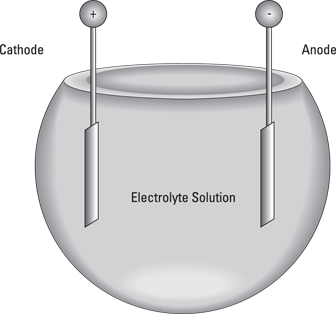
Figure 1-3: What goes on inside a battery.

Figure 1-4: Common batteries.
Cylindrical batteries come in four standard sizes: AAA, AA, C and D. Regardless of the size, these batteries provide 1.5 V each; the only difference between the smaller and larger sizes is that the larger batteries can provide more current. Technically, AAA, AA, C and D cells are just that – single cells, not batteries. But if you ask for a cell in your local hardware shop, people are likely to think you should be in one!
The cathode, or positive terminal, in a cylindrical battery is the end with the metal bump. The flat metal end is the anode, or negative terminal.
The rectangular battery in Figure 1-4 is a 9 V battery. It truly is a battery because that little rectangular box contains six small cells, each about half the size of an AAA cell. The 1.5 volts produced by each of these small cells combine to create a total of 9 volts.
Here are a few more battery facts:
![]() Available sizes: Besides AAA, AA, C, D and 9 V batteries, many other battery sizes are available. Most of these batteries are designed for special applications, such as digital cameras, hearing aids, laptop computers and so on.
Available sizes: Besides AAA, AA, C, D and 9 V batteries, many other battery sizes are available. Most of these batteries are designed for special applications, such as digital cameras, hearing aids, laptop computers and so on.
![]() Chemicals: All batteries contain chemicals that are toxic to you and to the environment. Treat them with care and don’t leave them unused for too long so that they end up leaking chemicals. When they’re dead put them in a recycling bin.
Chemicals: All batteries contain chemicals that are toxic to you and to the environment. Treat them with care and don’t leave them unused for too long so that they end up leaking chemicals. When they’re dead put them in a recycling bin.
![]() Measuring voltage: You can (and should) use your multimeter (a piece of equipment we describe in Book I, Chapter 8) to measure the voltage produced by your batteries. Set the multimeter to an appropriate DC voltage range (such as 20 V). Then, touch the red test lead to the positive terminal of the battery and the black test lead to the negative terminal. The multimeter tells you the voltage difference between the negative and positive terminals. For cylindrical batteries (AAA, AA, C or D) the reading should be about 1.5 V. For 9 V batteries, it should be about 9 V. It will be lower if they are exhausted through use or age.
Measuring voltage: You can (and should) use your multimeter (a piece of equipment we describe in Book I, Chapter 8) to measure the voltage produced by your batteries. Set the multimeter to an appropriate DC voltage range (such as 20 V). Then, touch the red test lead to the positive terminal of the battery and the black test lead to the negative terminal. The multimeter tells you the voltage difference between the negative and positive terminals. For cylindrical batteries (AAA, AA, C or D) the reading should be about 1.5 V. For 9 V batteries, it should be about 9 V. It will be lower if they are exhausted through use or age.
![]() Rechargeable batteries: These cost more than non-rechargeable batteries but last longer, because you can recharge them when they go dead. However, they start life with a slightly lower voltage and this gets worse with the number of recharge cycles.
Rechargeable batteries: These cost more than non-rechargeable batteries but last longer, because you can recharge them when they go dead. However, they start life with a slightly lower voltage and this gets worse with the number of recharge cycles.
![]() The technical term for a cell that can’t be recharged is a primary cell. A rechargeable cell is properly called a secondary cell.
The technical term for a cell that can’t be recharged is a primary cell. A rechargeable cell is properly called a secondary cell.
Building a lamp circuit
Project 1-1 shows you how to build a simple circuit that uses a battery to light a lamp. Although this circuit is quite simple, it helps illustrate the basic principles we’re explaining. Figure 1-5 shows the circuit assembled.

Figure 1-5: A simple lamp circuit.

Working with Switches
Switches are an important part of most electronic circuits. In the simplest case, most circuits contain an on/off switch to turn the circuit (unsurprisingly!) on and off. Many circuits also contain additional switches that control how the circuit works or to activate different features of the circuit.
Switches are mechanical devices with two or more leads (or terminals) that are internally connected to metal contacts, which the person operating the switch can open or close. When the switch is in the On position, the contacts are brought together to complete the circuit so that current can flow.
When the contacts are together, the switch is closed. When the contacts are apart, the switch is open and current can’t flow.
The following sections describe two ways to categorise switches: by the method used to operate the switch and by the connections made by the switch.
Moving switches in different ways
You can categorise switches by the movement a person uses to open or close the contacts. Figure 1-6 shows many different switch designs. Here are the most common types:
![]() Knife switch: The kind of switch Igor throws in a Frankenstein film to reanimate the creature. In a knife switch, the contacts are exposed for everyone to see.
Knife switch: The kind of switch Igor throws in a Frankenstein film to reanimate the creature. In a knife switch, the contacts are exposed for everyone to see.
![]() Pushbutton switch: Features a knob that you push to open or close the contacts. In some pushbutton switches, you push the switch once to open the contacts and then push again to close the contacts. In other words, each time you push the switch, the contacts alternate between opened and closed.
Pushbutton switch: Features a knob that you push to open or close the contacts. In some pushbutton switches, you push the switch once to open the contacts and then push again to close the contacts. In other words, each time you push the switch, the contacts alternate between opened and closed.
Other pushbutton switches are momentary contact switches, where contacts change from their default state only when the button is pressed and held down. The two types of momentary contact switches are:
• Normally open (NO): The default state of the contacts is open. When you push the button, the contacts are closed. When you release the button, the contacts open again. Thus, current flows only when you press and hold the button.
• Normally closed (NC): The default state of the contacts is closed. Thus, current flows until you press the button. When you press the button, the contacts are opened and current doesn’t flow. When you release the button, the contacts close again and current resumes.
![]() Rocker switch: Has a seesaw action. You press one side of the switch down to close the contacts and press the other side down to open the contacts.
Rocker switch: Has a seesaw action. You press one side of the switch down to close the contacts and press the other side down to open the contacts.
![]() Rotary switch: Contains a knob that you turn to open and close the contacts. The switch in the base of many tabletop lamps is an example of a rotary switch.
Rotary switch: Contains a knob that you turn to open and close the contacts. The switch in the base of many tabletop lamps is an example of a rotary switch.
![]() Slide switch: Features a knob that you can slide back and forth to open or close the contacts.
Slide switch: Features a knob that you can slide back and forth to open or close the contacts.
![]() Toggle switch: Contains a lever that you flip up or down to open or close the contacts. Common household light switches are examples of toggle switches.
Toggle switch: Contains a lever that you flip up or down to open or close the contacts. Common household light switches are examples of toggle switches.

Figure 1-6: You can find a switch for every need.
Making connections with poles and throws
You can classify switches by the connections they make. If you were under the impression that switches simply turn circuits on and off, guess again. Two important factors determine what types of connections a switch makes:
![]() Poles: A switch pole refers to the number of separate circuits that the switch controls:
Poles: A switch pole refers to the number of separate circuits that the switch controls:
• A single-pole switch controls just one circuit.
• A double-pole switch controls two separate circuits.
A double-pole switch is like two separate single-pole switches that are mechanically operated by the same lever, knob or button.
![]() Throw: The number of throws indicates how many different output connections each switch pole can connect its input to. Figure 1-7 shows the two most common types:
Throw: The number of throws indicates how many different output connections each switch pole can connect its input to. Figure 1-7 shows the two most common types:
• A single-throw switch is a simple on/off switch that connects or disconnects two terminals. When the switch is closed, the two terminals are connected and current flows between them. When the switch is opened, the terminals are not connected and so current doesn’t flow.
• A double-throw switch connects an input terminal to one of two output terminals. Thus, a double-pole switch has three terminals. One of the terminals is called the common terminal. The other two terminals are often referred to as A and B. When the switch is in one position, the common terminal is connected to the A terminal, and so current flows from the common terminal to the A terminal but no current flows to the B terminal. When the switch is moved to its other position, the terminal connections are reversed: current flows from the common terminal to the B terminal, but no current flows though the A terminal.

Figure 1-7: Single and double-throw switches.
Switches vary in the number of poles and the number of throws. In theory, any number of poles and any number of throws is possible. Most switches, however, have one or two poles and one or two throws. The result is four common combinations, as described in the following list. We show the symbols used in schematic diagrams for each of these switches in the margin:
![]()
![]() SPST (single pole, single throw): A basic on/off switch that turns a single circuit on or off. An SPST switch has two terminals: one for the input and one for the output.
SPST (single pole, single throw): A basic on/off switch that turns a single circuit on or off. An SPST switch has two terminals: one for the input and one for the output.
![]()
![]() SPDT (single pole, double throw): An SPDT switch routes one input circuit to one of two output circuits. This type of switch is sometimes called an A/B switch, because it lets you choose between two circuits, called A and B. An SPDT switch has three terminals: one for the input and two for the A and B outputs.
SPDT (single pole, double throw): An SPDT switch routes one input circuit to one of two output circuits. This type of switch is sometimes called an A/B switch, because it lets you choose between two circuits, called A and B. An SPDT switch has three terminals: one for the input and two for the A and B outputs.
![]()
![]() DPST (double pole, single throw): A DPST switch turns two circuits on or off. A DPST switch has four terminals: two inputs and two outputs.
DPST (double pole, single throw): A DPST switch turns two circuits on or off. A DPST switch has four terminals: two inputs and two outputs.

![]() DPDT (double pole, double throw): A DPDT switch routes two separate circuits, connecting each of two inputs to one of two outputs. A DPDT switch has six terminals: two for the inputs, two for the A outputs and two for the B outputs.
DPDT (double pole, double throw): A DPDT switch routes two separate circuits, connecting each of two inputs to one of two outputs. A DPDT switch has six terminals: two for the inputs, two for the A outputs and two for the B outputs.
Check out these other facts about poles and throws:
![]() Switches with more than two poles or more than two throws aren’t commonplace, but they do exist. Rotary switches lend themselves especially well to having many throws. For example, the rotary switch in a multimeter typically has 16 or more throws, one for each range of measurement the meter can make.
Switches with more than two poles or more than two throws aren’t commonplace, but they do exist. Rotary switches lend themselves especially well to having many throws. For example, the rotary switch in a multimeter typically has 16 or more throws, one for each range of measurement the meter can make.
![]() A common variation of a double throw switch is to have a middle position that doesn’t connect to either output. Often called centre open, this type of switch has three positions, but only two throws. For example, an SPDT centre open switch can switch one input between either of two outputs, but in its centre position, neither output is connected.
A common variation of a double throw switch is to have a middle position that doesn’t connect to either output. Often called centre open, this type of switch has three positions, but only two throws. For example, an SPDT centre open switch can switch one input between either of two outputs, but in its centre position, neither output is connected.
![]() When you’re stocking up on switches to have on hand, buy DPDT switches instead of single pole or single throw switches, because a DPDT can be used when a circuit calls for a simpler SPST, SPDT or DPST switch. You can use a DPDT switch when a simpler type is specified, because no law says that you have to wire all the contacts on the switch. For example, to use a DPDT switch as an SPST switch, you just use one of the poles and one of the throws and leave the other connections unused.
When you’re stocking up on switches to have on hand, buy DPDT switches instead of single pole or single throw switches, because a DPDT can be used when a circuit calls for a simpler SPST, SPDT or DPST switch. You can use a DPDT switch when a simpler type is specified, because no law says that you have to wire all the contacts on the switch. For example, to use a DPDT switch as an SPST switch, you just use one of the poles and one of the throws and leave the other connections unused.
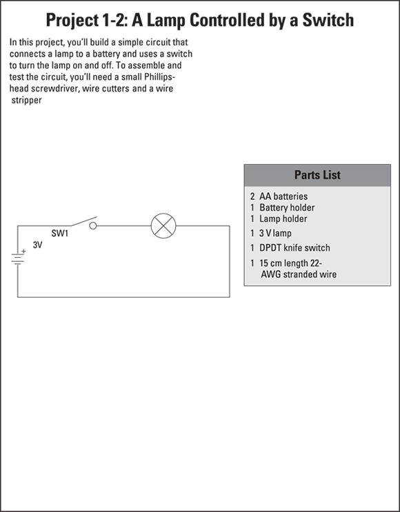
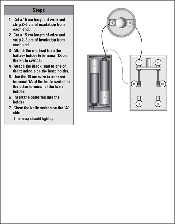
Building a switched lamp circuit
Project 1-2 presents a simple construction project that lets you explore the use of a simple on/off switch to control a lamp. Figure 1-8 shows the assembled project.
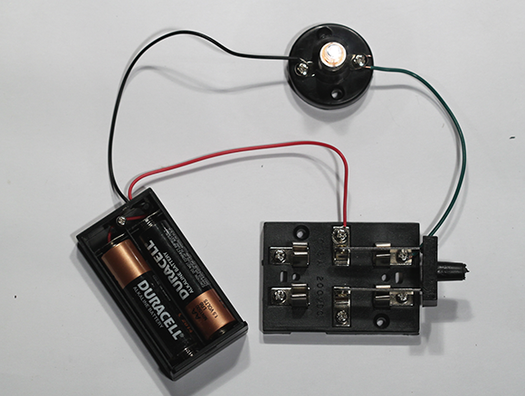
Figure 1-8: The switched lamp project.
This project and the remaining projects in this chapter use a RadioShack DPDT knife switch, pictured in Figure 1-9, which you can order online from www.t2retail.co.uk. You can use a DPDT toggle or rocker switch instead, which you can buy at your high-street electronics shop. In fact you're unlikely to use a knife switch in an actual electronic circuit, but one like this is useful when practising, because it's entirely exposed and you can see how it works. Plus, they come on their own base and have screw terminals, which makes connecting them in temporary circuits simple because you don't have to do any soldering.
As you can see in Figure 1-9, the knife switch is a double pole, double throw (DPDT) switch, which means it operates like two SPDT switches that are mechanically linked. We number the six terminals on the switch 1X, 1A, 1B, 2X, 2A and 2B:
![]() 1 and 2: Designate which of the two circuits is being switched.
1 and 2: Designate which of the two circuits is being switched.
![]() X terminals: The input terminals in the centre of the switch.
X terminals: The input terminals in the centre of the switch.
![]() A and B terminals: For the two possible outputs.
A and B terminals: For the two possible outputs.
Thus, when the switch is flipped one way, 1X is connected to 1A and 2X is connected to 2A. When the switch is flipped the other way, 1X is connected to 1B and 2X is connected to 2B.
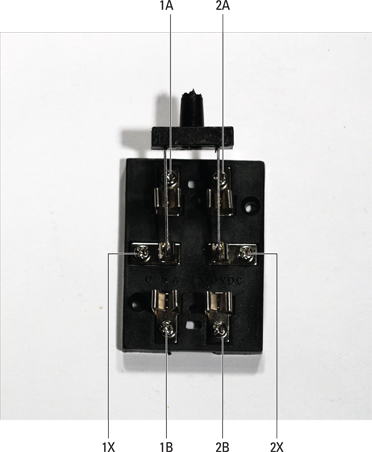
Figure 1-9: The DPDT knife switch.
If you want to experiment with different variations of this project, try the following:
![]() Move the switch from the positive side of the circuit to the negative side. In other words, connect the red lead from the battery holder to the lamp and connect the black lead to the 1X terminal on the switch.
Move the switch from the positive side of the circuit to the negative side. In other words, connect the red lead from the battery holder to the lamp and connect the black lead to the 1X terminal on the switch.
The circuit functions the same, which shows that the location of a switch in a circuit often doesn’t matter. If the circuit is broken anywhere, current can’t flow. Thus, whether the switch is before or after the lamp doesn’t matter.
![]() Cut a second 15 cm piece of wire and strip the insulation from both ends. Then, wire the circuit so that the red battery lead goes to switch terminal 1X, the black lead goes to switch terminal 2X, one of the wires goes from switch terminal 1A to one of the lamp terminals, and the other wire goes from switch terminal 2A to one of the lamp terminals.
Cut a second 15 cm piece of wire and strip the insulation from both ends. Then, wire the circuit so that the red battery lead goes to switch terminal 1X, the black lead goes to switch terminal 2X, one of the wires goes from switch terminal 1A to one of the lamp terminals, and the other wire goes from switch terminal 2A to one of the lamp terminals.
You’ve created the circuit shown in Figure 1-10. In this circuit, the knife switch is used as a DPST (double pole, single throw) switch to interrupt the circuit on the negative and the positive side of the lamp.

Figure 1-10: Using a DPST switch to control a lamp.
Understanding Series and Parallel Circuits
Whenever you have circuits that consist of more than one component, those components have to be linked together. The two ways to connect components in a circuit are in series and in parallel. Figure 1-11 illustrates how you can use series and parallel circuits to connect two lamps in a single circuit.
In a series connection, components are connected end to end, so that current flows first through one and then through the other. As you can see in the top circuit in Figure 1-11, the current goes through one lamp and then the other. The lamps are strung together end to end.

Figure 1-11: Lamps connected in series and in parallel.
A drawback of series connections is that if one component fails in a way that results in an open circuit, the entire circuit is broken and none of the components work. For example, if one of the lamps in the series circuit in Figure 1-11 burns out, neither lamp works because current must flow through both lamps for the circuit to be complete.
In the parallel connection shown in Figure 1-11, each lamp has its own direct connection to the battery. This arrangement avoids the if-one-fails-they-all-fail nature of series connections. In a parallel connection, the components don’t depend on each other for their connection to the battery. Thus, if one lamp burns out, the other continues to burn.
An interesting thing happens with voltage when components are connected in series: the voltages present at each component are divided up. For example, in a circuit with a 3 V battery and two identical lamps connected in series, each lamp sees only 1.5 V. If you connect three identical lamps in series, each lamp sees only 1 V.
You can measure the voltage seen by any component in a circuit by setting your multimeter to an appropriate voltage range and then touching the leads to both sides of the component. The voltage you measure is called the component’s voltage drop.
Building a series lamp circuit
In Project 1-3, you build a simple circuit that connects two lamps in series. You then use your multimeter to measure the voltages at various points in the circuit. The completed project is shown in Figure 1-12.

Figure 1-12: Lamps connected in series.


Building a parallel lamp circuit
In Project 1-4, you build a circuit that connects two lamps in parallel and use your multimeter to measure voltages within various points in the circuit. The completed project is shown in Figure 1-13.

Figure 1-13: Lamps connected in parallel.


Using Switches in Series and Parallel
Just as with lamps (see the preceding section), you can also connect switches in series or parallel. For example, Figure 1-14 shows two circuits that each use a pair of single pole, single throw (SPST) switches to turn a lamp on or off (check out the earlier section ‘Making connections with poles and throws’ for the different switch types). In the top circuit, the switches are wired in series. In the lower one, the switches are wired in parallel.
The interesting thing to note about wiring switches in series is that both switches must be closed in order to complete the circuit. A great example of switches wired in series is in the typical nuclear-war film, where two people have to flip a switch in order to launch the missiles. Switches wired in series means that Denzel Washington and Gene Hackman must agree to launch the missiles (a sensible precaution when one is as mad as a hatter!).
When switches are wired in parallel, closing either switch completes the circuit. Thus, parallel switches are often used when you want the convenience of controlling a circuit from two different locations. If the nuclear-missile switches were wired in parallel, either Denzel Washington or Gene Hackman on his own can fire the missiles.

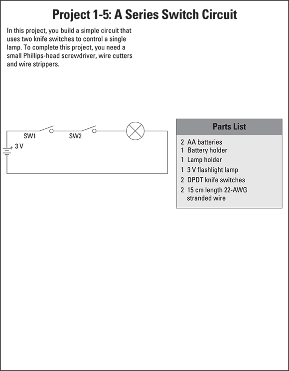
Figure 1-14: Schematic diagrams for series and parallel switch circuits.
Building a series switch circuit
Project 1-5 presents a simple project that uses two switches to open or close a circuit that lights a lamp. The switches are wired in series, and so both switches have to be closed to light the lamp. Figure 1-15 shows the completed project.
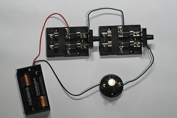
Figure 1-15: The assembled series switch circuit.

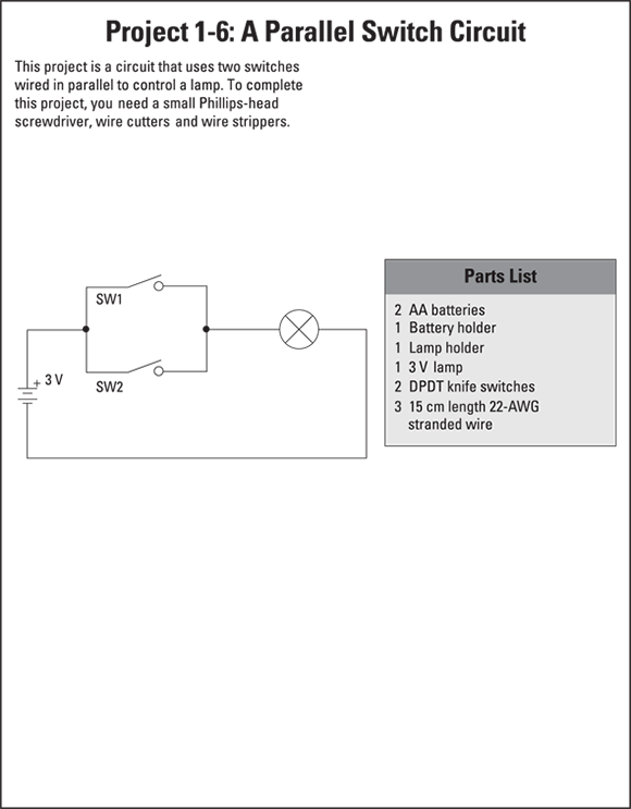
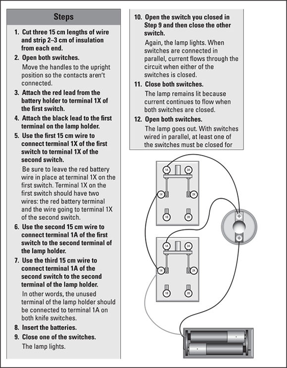
Building a parallel switch circuit
In Project 1-6, you build a simple circuit that uses two switches wired in parallel to control a lamp. Because the switches are wired in parallel, the lamp lights if either of the switches is closed. Figure 1-16 shows the completed project.
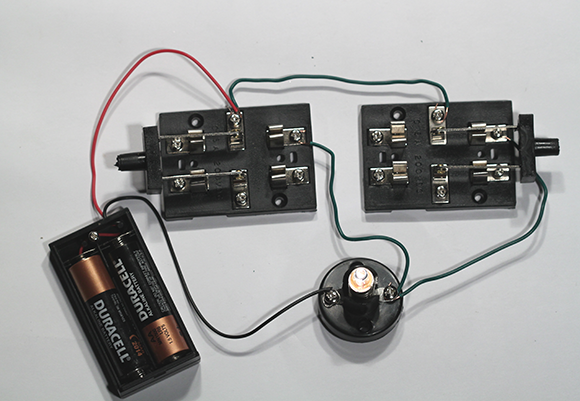
Figure 1-16: The assembled parallel switch circuit.
Switching between two lamps
In Project 1-7, you build a simple circuit that uses a single pole, double throw (SPDT) to switch a circuit between one of two lamps. In other words, one of two lamps lights depending on the position of the switch. This type of switching is a common requirement in electronic circuits. Figure 1-17 shows the completed circuit.
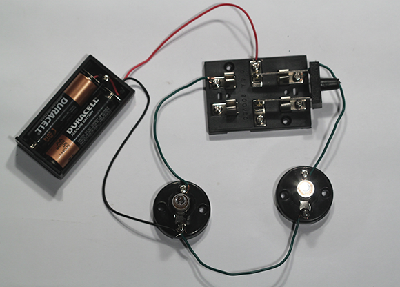
Figure 1-17: The switch controls two lamps.
An interesting variant of the circuit in Project 1-7 uses both poles of the DPDT knife switch (from Project 1-2 in the earlier section ‘Building a switched lamp circuit’) to switch the circuit on the negative and positive sides of the lamp. For this circuit, you need four 15 cm wires. Connect the six terminals of the DPDT switch as follows:
|
Terminal |
Connect To |
|
1X |
Red battery lead |
|
1A |
Terminal 1 of second lamp |
|
1B |
Terminal 1 of first lamp |
|
2X |
Black battery lead |
|
2A |
Terminal 2 of second lamp |
|
2B |
Terminal 2 of first lamp |
Figure 1-18 shows this circuit assembled.

Figure 1-18: Another way to control two lamps.
Building a three-way lamp switch
Many homes and offices have hallways with a light switch at both ends. You can turn the light on or off by flipping either switch. This kind of switching arrangement is called a three-way switch.
If you think about it, how these three-way switches work is a bit puzzling. If the light is on, flipping either switch turns it off. If the light is off, flipping either switch turns it on. Imagine that you flip one switch to its On position and the light goes on, and then you go to the other switch, flip it to turn the light off and come back to the first switch. It’s still in its On position, but the light is off. To turn the light back on, you can flip the first switch again.
In other words, sometimes the light is on when the switch is up, sometimes it’s on when the switch is down. How can this be?
The answer is that both switches are single pole, double throw (SPDT) switches (flip to the earlier section ‘Making connections with poles and throws’ for a definition), and they’re wired in series so that both switches must be up or both must be down to complete the circuit. If one switch is up and the other is down, the circuit is open.
Sometimes electricians install one of the switches upside down or wire the three-way switch backwards just to confuse you. Then, the switches work backwards: if both switches are up or if both switches are down, the circuit is open and the lamp lights only when one switch is up and the other is down. But that’s not the normal way to wire a three-way switch.
In Project 1-8, you build a simple circuit that uses two SPDT switches to show how a three-way light switch works. Figure 1-19 shows the completed project.
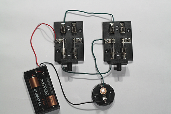
Figure 1-19: The completed three-way light switch circuit.


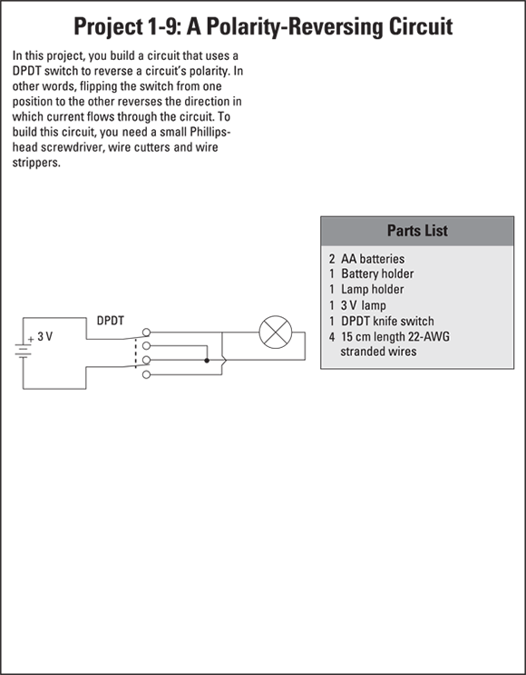
Reversing Polarity
Project 1-9 shows you a common trick: using a double pole, double throw (DPDT) switch (which we explain in the earlier section ‘Making connections with poles and throws’) to reverse the polarity of a circuit.
One common use for this technique is powering a DC motor with the circuit. When you reverse the polarity of a DC motor, the motor spins in the opposite direction. Therefore, you can use a DPDT switch to control the direction in which a DC motor turns. Figure 1-20 shows the assembled project.
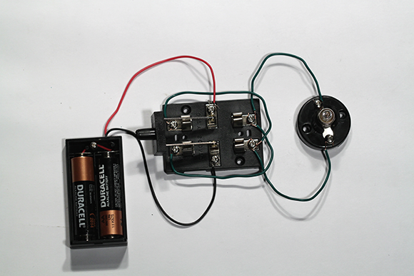
Figure 1-20: The assembled polarity-reversing circuit.