
Chapter 8
Measuring Circuits with a Multimeter
In This Chapter
![]() Familiarising yourself with a multimeter
Familiarising yourself with a multimeter
![]() Measuring current, voltage and resistance
Measuring current, voltage and resistance
![]() Looking at your first electronics equation: Ohm’s Law
Looking at your first electronics equation: Ohm’s Law
Just think how great it would be if every circuit you built worked right the first time you built it. You’d quickly develop a reputation as an electronics genius and in no time at all be the president of Intel.
But in the real world, a circuit doesn’t always work correctly the first time. Then you have two options: you can scratch your head and stare at it for hours on end, or you can pull out your test equipment and analyse the circuit to find out what’s wrong.
In this chapter, you discover how to use one of the electronics engineer’s favourite tools – the multimeter, which contains several different meters that can measure current, voltage and resistance. Learn how to use it well because it’s going to be your trusty companion throughout your adventures in electronics.
Looking at Multimeters
You know those late-night TV ads that try to sell you amazing kitchen gadgets that are like a combination blender, juicer, food processor, mixer and bottle opener all in one? A multimeter is kind of like one of those daft gadgets, except that a multimeter really can do all the things it claims without dozens of confusing attachments. And, unlike the daft kitchen gadgets, the things a multimeter can do turn out to be genuinely useful.
 Along with a good soldering iron, a good multimeter is the most important item in your toolbox.
Figure 8-1 shows a simple, inexpensive multimeter. You can buy this sort of model from your local electronics shop or via the Internet for under £10 and it’s sufficient when you’re just getting started. Eventually, you probably want to invest a little more money in a better-quality multimeter.

Figure 8-1: You can buy a basic digital multimeter like this one for under £10.
The multimeter in Figure 8-1 is a digital one, which displays its values using a digital display that shows the numbers for the measurements being taken. The alternative to a digital multimeter is an analogue one, which shows its readings by moving a needle across a printed scale. To determine the value of a measurement, you simply read the scale behind the needle.
Figure 8-2 shows a typical analogue multimeter. This one happens to be one of our favourites. Even though it’s old enough to be called vintage, it’s still an excellent and accurate meter. One of the benefits of spending a little more to buy quality equipment is that you get many years – sometimes decades – of reliable service.

Figure 8-2: An analogue multimeter.
The following list describes the various parts that make up a typical multimeter:
![]() Display or meter: Indicates the value of the measurement being taken. In a digital multimeter, the display is a number that indicates the amperage (current), voltage or resistance being measured. In an analogue meter, a needle moves across a printed scale to indicate the current, voltage or resistance. To get the value, you look straight down at the needle and read the scale printed behind it.
Display or meter: Indicates the value of the measurement being taken. In a digital multimeter, the display is a number that indicates the amperage (current), voltage or resistance being measured. In an analogue meter, a needle moves across a printed scale to indicate the current, voltage or resistance. To get the value, you look straight down at the needle and read the scale printed behind it.
![]() Selector: Most multimeters – digital or analogue – have a dial that you can turn to tell the meter what you want to measure. The various settings on this dial indicate not only the type of measurement you want to make (voltage, current or resistance), but also the range of the expected measurements. The range is indicated by the maximum amount of voltage, current or resistance that the meter can measure.
Selector: Most multimeters – digital or analogue – have a dial that you can turn to tell the meter what you want to measure. The various settings on this dial indicate not only the type of measurement you want to make (voltage, current or resistance), but also the range of the expected measurements. The range is indicated by the maximum amount of voltage, current or resistance that the meter can measure.
 Higher ranges let you measure higher values, but with less precision. For example, the analogue multimeter in Figure 8-2 has the following ranges for reading direct current (DC) voltage: 2.5 V, 10 V, 50 V, 250 V and 500 V. If you use the 2.5 V range, you can easily tell differences of a tenth of a volt, such as the difference between 1.6 and 1.7 V. But when the range is set to the 500 V range, you’re lucky to pick out differences of 10 V.
![]() On/off switch: Some multimeters have a separate on/off switch but others don’t. Instead, one of the positions on the selector dial is ‘Off’. If your meter doesn’t give you any readings, check to make sure that the power switch is turned on.
On/off switch: Some multimeters have a separate on/off switch but others don’t. Instead, one of the positions on the selector dial is ‘Off’. If your meter doesn’t give you any readings, check to make sure that the power switch is turned on.
![]() Test leads: The test leads are a pair of red and black wires with metal probes on their ends. One end of these wires plugs into the meter and you use the other end to connect to the circuits you want to measure. The red lead is positive and the black lead is negative.
Test leads: The test leads are a pair of red and black wires with metal probes on their ends. One end of these wires plugs into the meter and you use the other end to connect to the circuits you want to measure. The red lead is positive and the black lead is negative.
Discovering What a Multimeter Measures
A meter is a device that measures electrical quantities. A multimeter, therefore, is a combination of several different types of meters all in one box. At the minimum, a multimeter combines three distinct types of meters (ammeter, voltmeter and ohmmeter) into a single device, as we describe in the following sections.
Keeping current with the ammeter
As you find out in Chapter 2 of this minibook, current is the flow of electric charge through a conductor. Current is measured in units called amperes and a meter that measures amperage is called an ammeter.
Very few electronic circuits have currents so strong that they can be measured in actual amperes. Therefore, ammeters usually measure current in milliamperes (also called a milliamp and usually abbreviated mA). One milliamp is 1,000th of an ampere; in other words, an amp contains 1,000 milliamps.
 A happy accident
The world’s first ammeter was invented by a Dutch physicist named Hans Christian Oersted in 1821, when he accidentally left a compass next to a wire that had an electric current flowing through it. Hans noticed that when the current flowed, the needle moved away from its normal northerly orientation and pointed towards the wire. This is because current moving through a wire creates a magnetic field around the wire, and the magnetic field was strong enough to attract the magnetised end of the compass needle.
After fooling around with it for a bit, Hans discovered that the more current he ran through the wire, the further the needle strayed from north. Soon he figured out that he could use his discovery to measure the amount of current flowing through a circuit. Analogue ammeters work by this same principle even today.
Calculating voltage with the voltmeter
In Chapter 2 of this minibook, you find out all about a second fundamental quantity of electricity, voltage, a term that refers to the difference in electric charge between two points. If those two points are connected to a conductor, a current will flow through the conductor. Thus, voltage is the instigator of current.
The unit of voltage is, naturally, the volt, and a device that measures voltage is called a voltmeter.
All other things being equal, a change in the amount of voltage between two points results in a corresponding change in current. Thus, if you can keep things equal, you can measure voltage by measuring current, and as we discuss in the preceding section you can measure current with an ammeter.
The basic difference between an ammeter and a voltmeter is that in an ammeter, you let current run directly through the meter so that you can measure the amount of current. In a voltmeter, the current is first run through a very large resistor and then through the ammeter, and the device makes the necessary calculations as follows.
In Book II, Chapter 2, you find out that a direct relationship exists between voltage, resistance and current in an electrical circuit. In particular, if you know any two of these quantities, the third one is easy to calculate. In a voltmeter, a large fixed resistance is used, and the ammeter measures the current. Because you know the amount of the fixed resistance and the amount of current, you can easily calculate the amount of voltage across the circuit.
Don’t worry; you don’t have to do any maths to calculate this voltage. The voltmeter does that for you. In an analogue voltmeter, the calculation is built in to the scale that’s printed on the meter, so all you have to do is look at the position of the needle on the scale to read the voltage. In a digital voltmeter, the voltage is automatically calculated and displayed digitally.
For a brief explanation of the relationship between current, voltage and resistance, see the later sidebar ‘A quick look at Ohm’s law’.
Sensing resistance with the ohmmeter
A resistor is a material that resists the flow of current. How much the current is restricted is a function of the amount of resistance in the resistor, which is measured in units called ohms. The symbol for ohms is the Greek letter omega, Ω. A device that measures resistance is called an ohmmeter.
Like voltage, resistance can also be measured with an ammeter. As we state in the preceding section, a direct relationship exists between voltage, resistance and current in any circuit, and if you know any two of these quantities you can easily calculate the third. So to measure voltage, a voltmeter provides a fixed resistance, uses an ammeter to measure the current and then uses the resistance and current to calculate the voltage.
To measure the resistance of a circuit, an ohmmeter provides a fixed amount of voltage across the circuit, uses an ammeter to measure the current that flows through the circuit and then uses the amount of voltage the meter provides and the amount of current the meter reads to calculate the resistance.
As with voltage, you don’t have to do this calculation (phew!); it’s automatically made by digital multimeters and is built in to the meter scale for analogue multimeters. Thus, all you have to do is read the display or the needle on the meter to determine the resistance.
A quick look at Ohm’s law
In Book II, Chapter 2, you take a close look at resistors and at Ohm’s law, which is one of the most important mathematical relationships in electronics. Here we give you a brief overview without going into all the details.
Ohm’s law describes a fundamental relationship between current, voltage and resistance in an electrical circuit. Remember that voltage is the difference in electrical charge between two points, and that if a conductor connects those two points current will flow through the conductor.
Other than exotic superconductors (which exist only in laboratory experiments), no conductor is perfect. All conductors have a certain amount of resistance that inhibits the flow of current. The greater this resistance, the less the current will flow. The less this resistance is, the more the current will flow.
Ohm’s law is a mathematical formula that describes the relationship between current, voltage and resistance. Here’s the formula:
![]()
In other words, the amount of current running through a circuit is equal to the amount of voltage across the circuit divided by the amount of resistance in the circuit. The amount of current in amperes is represented by the letter I (don’t ask why; it just is). V represents voltage in volts and R represents resistance in ohms.
With basic maths you can use this equation to calculate the voltage if you know the current and the resistance. Then, the formula becomes:
V = IR
In other words, voltage is equal to current times resistance.
Similarly, you can calculate resistance if you know the current and the voltage. Then, the formula becomes:
![]()
In other words, resistance equals the voltage divided by the current.
Meeting some other measurements
All multimeters can measure current, voltage and resistance, but some can perform other types of measurements as well. For example, certain meters can measure the capacitance of capacitors and some can test diodes or transistors. These features are handy, but not essential.
Reading schematic symbols for meter functions
Ammeter, voltmeter and ohmmeters are often included in schematic diagrams. When they are, the following symbols are used:

Using Your Multimeter
In this section, we show you how to use your multimeter to measure current, voltage and resistance in a simple circuit. The circuit being measured consists of just three components: a 9 V battery, a light-emitting diode (LED) and a resistor. Figure 8-3 shows the schematic for this circuit.
Building a circuit to measure
If you want to follow along with the measuring procedures detailed in the following sections, you can build this circuit on a solderless breadboard. You need the following parts:
![]() Small solderless breadboard
Small solderless breadboard
![]() 470 Ω, 1/4W resistor, 5 per cent tolerance
470 Ω, 1/4W resistor, 5 per cent tolerance
![]() Red LED, 5 mm
Red LED, 5 mm
![]() 9 V battery snap connector
9 V battery snap connector
![]() 9 V battery
9 V battery
![]() Short length of jumper wire (25 mm or less)
Short length of jumper wire (25 mm or less)

Figure 8-3: A simple circuit with battery, resistor and LED.
Figure 8-4 shows the circuit installed on the breadboard. Here are the steps for building this circuit:
1. Connect the battery snap connector.
Insert the red lead in the top bus strip and the black lead in the bottom bus strip. Any hole is fine, but connecting the battery at the very end of the breadboard makes sense.
2. Connect the resistor.
Insert one end of the resistor into any hole in the bottom bus strip. Then, pick a row in the nearby terminal strip and insert the other end into a hole in that terminal strip.
3. Connect the LED.
Notice that the leads of the LED aren’t the same length; one lead is shorter than the other. Insert the short lead into a hole in the top bus strip, and then insert the longer lead into a hole in a nearby terminal strip.
Insert the LED into the same row as the resistor. In Figure 8-4, the LED and the resistor are in row 26.
4. Use the short jumper wire to connect the terminal strips into which you inserted the LED and the resistor.
The jumper wire straddles the gap that runs down the middle of the breadboard.
5. Connect the battery to the snap connector.
The LED lights up. If it doesn’t, double-check your connections to make sure that the circuit is assembled correctly. If it still doesn’t light up, try reversing the leads of the LED (you may have inserted it backwards). If that doesn’t work, try a different battery.
 Do not connect the LED directly to the battery without a resistor. If you do, the LED flashes brightly – it may even go bang – and then it’s dead forever.
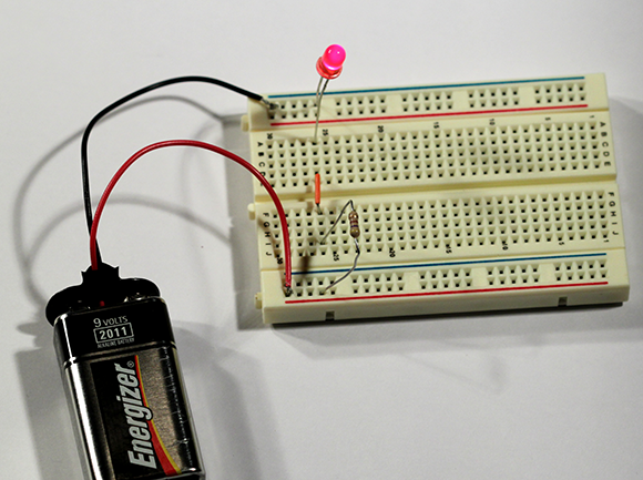
Figure 8-4: The LED circuit assembled on a breadboard.
Measuring current
Electric current is measured in amperes, but in most electronics work you measure current in milliamps (or mA). To measure current, you need to connect the two leads of the ammeter in the circuit so that the current flows through the ammeter. In other words, the ammeter must become a part of the circuit itself.
The only way to measure the current flowing through the LED circuit that’s shown in Figure 8-3 is to insert your ammeter into the circuit. Figure 8-5 shows one way to do so. Here, the ammeter is inserted into the circuit between the LED and the resistor.

Figure 8-5: Measuring current in the LED circuit.
Note that where in this circuit you insert the ammeter doesn’t matter. You get the same current reading whether you insert the ammeter between the LED and the resistor, between the resistor and the battery, or between the LED and the battery.
To measure the current in the LED circuit, follow these steps:
1. Set your multimeter’s range selector to a DC milliamp range of at least 20 mA.
This circuit uses DC and so you need to ensure that the multimeter is set to a DC current range.
2. Remove the jumper wire that connects the two terminal strips.
The LED goes dark, because removing the jumper wire breaks the circuit.
3. Touch the black lead from the multimeter to the LED lead that connects to the terminal strip (not the bus strip).
4. Touch the red lead from the multimeter to the resistor lead that connects to the terminal strip (not the bus strip).
The LED lights up again, because the ammeter is now a part of the circuit and current can flow.
5. Read the number on the multimeter display.
It should read between 12 and 13 mA. (The precise reading depends on the exact resistance value of the resistor. Resistor values aren’t exact, and so even though you’re using a 470 Ω resistor in this circuit, the actual resistance of the resistor may be anywhere from around 446 to 494 Ω. For more about this effect, check out Book II, Chapter 2.)
6. Congratulate yourself!
You’ve made your first official current measurement.
7. Replace the jumper wire you removed in Step 2 (after a suitable celebration).
If you forget to replace the jumper wire, the procedure we describe in the next section for measuring voltage doesn’t work.
Don’t connect the ammeter as follows in this circuit:
![]() Don’t connect the ammeter directly across the two battery terminals. Doing so effectively shorts out the battery, which gets really hot, really fast.
Don’t connect the ammeter directly across the two battery terminals. Doing so effectively shorts out the battery, which gets really hot, really fast.
![]() Don’t connect one lead of the ammeter to the positive battery terminal and the other directly to the LED lead. That bypasses the resistor, which probably blows out the LED.
Don’t connect one lead of the ammeter to the positive battery terminal and the other directly to the LED lead. That bypasses the resistor, which probably blows out the LED.
![]() Don’t try to measure too big a current. Doing so will usually blow the fuse in a digital multimeter or trip a re-settable switch in an analogue meter.
Don’t try to measure too big a current. Doing so will usually blow the fuse in a digital multimeter or trip a re-settable switch in an analogue meter.
If you want to experiment a little more, try measuring the current at other places in the circuit. For example, remove the battery snap connector from the battery and then reconnect it so that just the negative battery terminal is connected. Then, touch the red meter lead to the positive battery terminal and the black lead to the lead of the resistor that’s connected to the bus strip (not the lead that’s connected to the terminal strip). This measures the current by inserting the ammeter between the resistor and the battery. You get the same value as when you measure between the LED and the resistor.
You can use a similar method to measure the current between the LED and the negative battery terminal. Again, the result should be the same.
Measuring voltage
Measuring voltage is a little easier than measuring current because you don’t have to insert the meter into the circuit. Instead, all you have to do is touch the leads of the multimeter to any two points in the circuit. When you do, the multimeter displays the voltage that exists between those two points.
Figure 8-6 shows how you can insert a voltmeter into the LED circuit to measure voltage. In this case, the voltage is measured across the battery. It probably reads in the vicinity of 8.3 V (9 V batteries rarely provide a full 9 V).

Figure 8-6: Measuring voltage in the LED circuit.
To measure voltages in the LED circuit, first put the circuit back together (if you took it apart to measure currents in the preceding section). Then, spin the multimeter dial to a range whose maximum is at least 10 V. Now touch the leads to different spots in the circuit. To measure the voltage across the entire circuit as shown in Figure 8-6, touch the black lead to the LED lead that’s inserted into the negative bus strip and touch the red lead to the resistor lead that’s inserted into the positive bus strip.
Here’s an interesting exercise. Write down the following three voltage measurements:
![]() Across the battery: Connect the red meter lead to the resistor lead that’s inserted into the positive bus strip and the black meter lead to the LED lead that’s inserted into the negative bus strip.
Across the battery: Connect the red meter lead to the resistor lead that’s inserted into the positive bus strip and the black meter lead to the LED lead that’s inserted into the negative bus strip.
![]() Across the resistor: Connect the red meter lead to the resistor lead that’s inserted into the positive bus and the black meter lead to the other resistor lead.
Across the resistor: Connect the red meter lead to the resistor lead that’s inserted into the positive bus and the black meter lead to the other resistor lead.
![]() Across the LED: Connect the black meter lead to the LED lead that’s inserted into the negative bus and the red meter lead to the other LED lead.
Across the LED: Connect the black meter lead to the LED lead that’s inserted into the negative bus and the red meter lead to the other LED lead.
What do you notice about these three measurements? (The question’s a little bit of a puzzle, and so we don’t give the answer here; you can find it in Book II.)
Measuring resistance
Measuring resistances is similar to measuring voltages, with one key difference.
Before starting, disconnect all voltage sources from the circuit whose resistance you want to measure. That’s because the multimeter injects a known voltage into the circuit so that it can measure the current and then calculate the resistance. If any outside voltage sources are in the circuit, the voltage isn’t fixed and so the calculated resistance is wrong.
Here are the steps for measuring resistance in the LED circuit:
1. Remove the battery.
Just unplug it from the battery snap connector and set the battery aside.
2. Turn the meter selector dial to one of the resistance settings.
If you have an idea of what the resistance is, pick the smallest range that’s greater than the value you’re expecting. Otherwise, pick the largest range available on your meter.
3. Calibrate the meter if you’re using an analogue one.
You have to calibrate analogue meters before they can give an accurate resistance measurement. To calibrate an analogue meter, touch the two meter leads together. Then, adjust the meter’s calibration knob until the meter indicates 0 resistance.
4. Touch the meter leads to the two points in the circuit for which you want to measure resistance.
For example, to measure the resistance of the resistor, touch the meter leads to the two leads of the resistor. The result should be in the vicinity of 470 Ω.
You can discover loads more about measuring resistances in Book II, Chapter 2, but here are a few additional thoughts to tide you over:
![]() When you measure the resistance of an individual resistor or of circuits consisting of nothing other than resistors, the direction the current flows through the resistor doesn’t matter. Thus, you can reverse the multimeter leads and still get the same result.
When you measure the resistance of an individual resistor or of circuits consisting of nothing other than resistors, the direction the current flows through the resistor doesn’t matter. Thus, you can reverse the multimeter leads and still get the same result.
![]() Some components such as diodes pass current better in one direction than in the other. In that case, the direction of the current does matter. You can read about this effect in Book II, Chapter 5.
Some components such as diodes pass current better in one direction than in the other. In that case, the direction of the current does matter. You can read about this effect in Book II, Chapter 5.
![]() Resistors aren’t perfect. Thus, a 470 Ω resistor rarely provides exactly 470 Ω of resistance. The usual tolerance for resistors is 5%, which means that a 470 Ω resistor has somewhere between 446.5 and 493.5 Ω of resistance. For most circuits, this level of imprecision doesn’t matter. But in circuits where it does, you can use the ohmmeter function of your multimeter to determine the exact value of a particular resistor. Then, you can adjust the rest of your circuit accordingly. (We write more on this subject in Book III, Chapter 2.)
Resistors aren’t perfect. Thus, a 470 Ω resistor rarely provides exactly 470 Ω of resistance. The usual tolerance for resistors is 5%, which means that a 470 Ω resistor has somewhere between 446.5 and 493.5 Ω of resistance. For most circuits, this level of imprecision doesn’t matter. But in circuits where it does, you can use the ohmmeter function of your multimeter to determine the exact value of a particular resistor. Then, you can adjust the rest of your circuit accordingly. (We write more on this subject in Book III, Chapter 2.)