
Chapter 4: Grayboxing with Terrain and ProBuilder
Now that we have grasped all the necessary concepts to use Unity, let's start designing our first level. The idea in this chapter is to learn how to use the Terrain tool to create the Landscape of our game and then use ProBuilder to create the 3D mesh of the base with greater detail than using cubes. Using those tools, you will be able to create a prototype of any kind of scene and try out your idea before actually implementing it with final graphics.
Specifically, we will examine the following concepts in this chapter:
- Creating a Landscape with Terrain
- Creating Shapes with ProBuilder
Creating a Landscape with Terrain
So far, we have used Cubes to generate our level prototype, but we also learned that those shapes sometimes cannot represent all possible objects we could need. Imagine something irregular, such as a full terrain with hills, canyons, and rivers. This would be a nightmare to create using cubes. Another option would be to use 3D modeling software, but the problem with that is that the generated model will be so big and so detailed that it won't perform well, even on high-end PCs. In this scenario, we need to learn how to use Terrain, which we will do in this first section of this chapter.
In this section, we will cover the following concepts related to terrains:
- Discussing Height Maps
- Creating and configuring Height Maps
- Authoring Height Maps
- Adding Height Map details
Let's start talking about Height Maps, whose textures help us define the heights of our terrain.
Discussing Height Maps
If we create a giant area of the game with hills, canyons, craters, valleys, and rivers using regular 3D modeling tools, we will have the problem that we will use full detailed models for objects at all possible distances, thus wasting resources on details we won't see when the object is far away. We will see lots of terrain parts from a great distance, such as mountains and rivers, so this is a serious issue.
Unity Terrain tools use a technique called Height Maps to generate the terrain in a performant and dynamic way. Instead of generating large 3D models for the whole terrain, it uses an image called a Height Map, which looks like a top-down black and white photo of the terrain.
In the following figure, you can see a black and white top-down view of Scotland terrain heights, with white being a higher height and black being a lower height:

Figure 4.1 – Scotland´s Height Map
In the preceding image, you can easily spot the peaks of the mountains while looking for the whitest areas of the image. Everything below sea level is black, while anything in the middle using gradients of gray represents different heights between the minimum and maximum heights. The idea is that each pixel of the image determines the height of that specific area of the terrain.
Unity Terrain tools can automatically generate a Terrain 3D mesh from that image, saving us the hard drive space of having full 3D models of that terrain. Also, Unity will create the terrain as we move, generating high-detail models for nearby areas and lower-detail models for faraway areas, making it a performant solution.
In the following figure, you can see the mesh that was generated for the terrain. You can appreciate that the nearer parts of the terrain have more polygons than the further-away parts:

Figure 4.2 – Height Map generated mesh
Take into account that this technology also has its cons, such as the time it takes for Unity to generate those 3D models while we play and the inability to create caves, but for now, that's not a problem for us.
Now that we know what a Height Map is, let's see how we can use Unity Terrain tools to create our own Height Maps.
Creating and configuring Height Maps
If you click on GameObject | 3D Object | Terrain, you will see how a giant plane appears on your scene and that a Terrain object appears on your Hierarchy window. That's our terrain, and it is plain because its Height Map starts all black, so no height whatsoever is in its initial state. In the following screenshot, you can see what a brand new Terrain looks like:

Figure 4.3 – Terrain with no heights painted yet
Before you start editing your terrain, you must configure different settings such as the size and resolution of the Terrain's Height Map, and that depends on what you are going to do with it. This is not the same as generating a whole world. Remember that our game will happen in the Player´s Base, so the terrain will be small. In this case, an area that's 200 x 200 meters in size surrounded by mountains will be enough.
In order to configure our terrain for those requirements, we need to do the following:
- Select Terrain from the Hierarchy or Scene window.
- Look at the Inspector for the Terrain component and expand it if it is collapsed.
- Click on the wheel icon to switch to configuration mode. In the following screenshot, you can see where that button is located:

Figure 4.4 – Terrain settings button
- Look for the Mesh Resolution section.
- Change Terrain Width and Terrain Length to 200. This will say that the size of our terrain is going to be 200 x 200 meters.
- Terrain Height determines the maximum height possible. The white areas of our Height Map are going to be that size. We can reduce it to 500 just to limit the maximum peak of our mountains:

Figure 4.5 – Terrain resolution settings
- Look for the Texture Resolutions section.
- Change Heightmap Resolut to 257 x 257:

Figure 4.6 – Height Map resolution settings
Important Note
The Heightmap resolution is the size of the Heightmap image that will hold the heights of the different parts of the terrain. Using a resolution of 257 x 257 in our 200 x 200 meter terrain means that each square meter in the terrain will be covered by a little bit more than 1 pixel of the Heightmap. The higher the resolution per square meter, the greater detail you can draw in that area size. Usually, terrain features are big, so having more than 1 pixel per square meter is generally a waste of resources. Find the smallest resolution you can have that allows you to create the details you need.
Another initial setting you will want to set is the initial terrain height. By default, this is 0, so you can start painting heights from the bottom part, but this way, you can't make holes in the terrain because it's already at its lowest point. Setting up a little initial height allows you to paint river paths and holes in case you need them. In order to do so, do the following:
- Select Terrain.
- Click on the Brush button (second button).
- Set the dropdown to Set Height.
- Set the Height property to 50. This will state that we want all the terrain to start at 50 meters in height, allowing us to make holes with a maximum depth of 50 meters:

Figure 4.7 – Set Height terrain tool location
- Click the Flatten All button. You will see all the terrain has been raised by those 50 meters we specified earlier.
Now that we have properly configured our Height Map, let's start editing it.
Authoring Height Maps
Remember that the Height Map is just an image with the heights, so in order to edit it, we would need to paint the heights in that image. Luckily, Unity has tools that allow us to edit the terrain directly in the Editor and see the results of the modified heights directly. In order to do this, we must follow these steps:
- Select Terrain.
- Click the Brush button.
- Set the dropdown in Raise or Lower Terrain mode:

Figure 4.8 – Raise or Lower Terrain tool location
- Select the second brush in the Brushes selector. This brush has blurred borders to allow us to create softer heights.
- Set Brush Size to 30 so that we can create heights that span 30 meter areas. If you want to create subtler details, you can reduce this number.
- Set Opacity to 10 to reduce the amount of height we paint per second or click:

Figure 4.9 – Smooth edges brush
- Now, if you move the mouse in the Scene view, you will see a little preview of the height you will paint if you click on that area. Maybe you will need to navigate closer to the terrain to see it in detail:
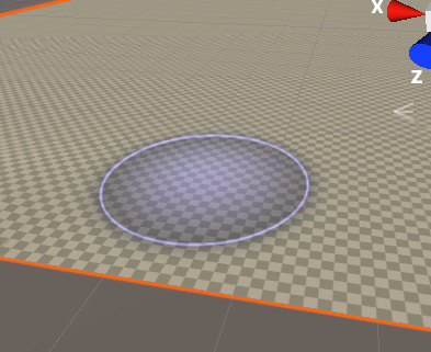
Figure 4.10 – Previsualization of the area to raise the terrain
Important Note
That checkered pattern you can see near the terrain allows you to see the actual size of the objects you are editing. Each cell represents a square meter. Remember that having a reference to see the actual size of the objects you are editing is useful to prevent creating too big or too small terrain features. Maybe you can put in other kinds of references, such as a big cube with accurate sizes representing a building to get a notion of the size of the mountain or lake you are creating. Remember that the cube has a default size of 1 x 1 x 1 meters, so scaling to (10,10,10) will give you a cube of 10 x 10 x 10 meters.
- Hold left-click and drag the cursor over the terrain to start painting your terrain heights. Remember that you can press Ctrl + Z (command+ Z on Mac) to revert any undesired change.
- Try to paint the mountains all around the borders of our area, which will represent the background hills of our base:

Figure 4.11 – Painted mountains around the edges of the terrain
Now, we have decent starter hills around our future base. We can also draw a river basin around our future base area. To do so, follow these steps:
- Place a cube with a scale of (50,10,50) in the middle of the terrain. This will act as a placeholder for the base we are going to create:

Figure 4.12 – Placeholder cube for the base area
- Select Terrain and the Brush button once more.
- Reduce Brush Size to 10.
- Holding the Shift key, left-click and drag the mouse over the terrain to paint the basin around our base placeholder. Doing this will lower the terrain instead of raising it:

Figure 4.13 – River basin around our placeholder base
Now, we have a simple but good starter terrain that gives us a basic idea of how it will look from our base's perspective. Before moving on, we will apply some finer details to make our terrain look a little bit better. In the next section, we will discuss how to simulate terrain erosion with different tools.
Adding Height Map details
In the previous section, we created a rough outline of the terrain. If you want to make it look a little bit realistic, then you need to start painting lots of tiny details here and there. Usually, this is done later in the level design process, but let's take a look now since we are exploring the Terrain tools. Right now, our mountains look very smooth. In real life, they are sharper, so let's improve that:
- Select Terrain and enable the Brush button.
- Set the dropdown in Raise or Lower Terrain mode.
- Pick the fifth brush. This one has an irregular layout so that we can paint a little bit of noise here and there.
- Set Brush Size to 50 so that we can cover a greater area:

Figure 4.14 – Cloud pattern brush for randomness
- Hold Shift and do small clicks over the hills of the terrain without dragging the mouse. Remember to zoom in to the areas you are applying finer details to because those can't be seen at great distances:

Figure 4.15 – Erosion generated with previous brush
This has added some irregularity to our hills. Now, let's imagine we want to have a flat area on the hills to put a decorative observatory or antenna. Follow these steps to do so:
- Select Terrain, Brush Tool, and Set Height from the dropdown.
- Set Height to 60.
- Paint an area over the hills. You will see how the terrain will raise if it's lower than 60 meters or became lower in areas greater than 60 meters:

Figure 4.16 – Flattened hill
- You can see that the borders have some rough corners that need to be smoothed:

Figure 4.17 – Non-smoothed terrain edges
- Change the dropdown to Smooth Height mode.
- Select the second brush with a size of 5 and an opacity of 10:

Figure 4.18 – Smooth Height brush
- Click and drag over the borders of our flat area to make them smoother:

Figure 4.19 – Smoothed terrain edges
We can keep adding details here and there, but we can settle with this for now. The next step is to create our Player's Base, but this time, let's explore ProBuilder in order to generate our geometry.
Creating Shapes with ProBuilder
So far, we have created simple scenes using cubes and primitive shapes, and that's enough for most of the prototypes you will create, but sometimes, you will have tricky areas of the game that would be difficult to model with regular cubes, or maybe you want to have some deeper details in certain parts of your game to get a visual of how the player will feel that area. In this case, we can use any 3D modeling tools for this, such as 3D studio, Maya, or Blender, but those can be difficult to learn and you probably won't need all their power at this stage of your development. Luckily, Unity has a simple 3D model creator called ProBuilder, so let's explore it.
In this section, we will cover the following concepts related to ProBuilder:
- Installing ProBuilder
- Creating a shape
- Manipulating the mesh
- Adding details
ProBuilder is not included by default in our Unity project, so let's start by learning how we can install it.
Installing ProBuilder
Unity is a powerful engine full of features, but having all those tools added to our project if we are not using all of them can make the engine run slower, so we need to manually specify which Unity tools we are using. To do so, we will use the Package Manager, a tool that we can use to see and select which Unity packages we are going to need. As you may recall, earlier, we talked about the Packages folder. This is basically what this Package Manager is modifying.
In order to install ProBuilder with this tool, we need to do the following:
- Click the Window | Package Manager option:

Figure 4.20 – Package Manager option
- In the window that just opened, be sure that Packages is in Unity Registry mode by clicking on the button saying Packages at the top-left part of the window and selecting Unity Registry:
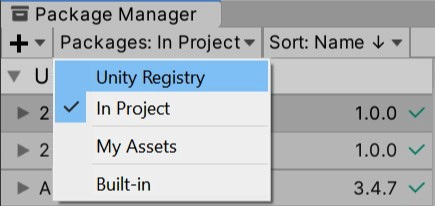
Figure 4.21 – Showing All Packages
- Wait a moment for the left list of packages to fill. Make sure you are connected to the internet to download and install the packages.
- Look at the ProBuilder package in that list and select it.
Important Note
Im using ProBuilder version 4.2.3, the newest version available at the moment of writing this book. While you can use a newer version, consider that the steps to use it may differ. You can look at older versions using the arrow at the left of the title.

Figure 4.22 – ProBuilder in the packages list
- Click on the Install button at the bottom right-hand side of the Package Manager:

Figure 4.23 – Install button
- Wait a moment for the package to install. You will notice the process has ended when the Install button has been replaced with an Up to Date label.
Now that we have installed ProBuilder in our project, let's use it!
Creating a Shape
We will start our base by creating a plane for our floor. We will do this by doing the following:
- Open ProBuilder and go to the Tools | ProBuilder | ProBuilder window:
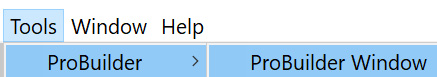
Figure 4.24 – ProBuilder Window option
- In the window that has opened, click the plus icon (+) at the right of the New Shape button:

Figure 4.25 – New Shape option
- In the Shape Selector, select Plane.
- Set Width and Length to 50.
- Set the Width and Length segments to 2. We will need those subdivisions later:

Figure 4.26 – New Shape settings
- Click the Build button to confirm the Plane.
- Click the first button of the four ProBuilder buttons in the Scene view to enable movement of the entire plane:
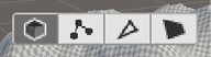
Figure 4.27 – Select object tool
- Replace the placeholder cube with this floor:

Figure 4.28 – Plane subdivided in a 3 x 3 grid
Now that we have created the floor, let's learn how we can manipulate its vertexes to change its shape.
Manipulating the mesh
If you select the plane, you will see that it is subdivided into a 3 x 3 grid because we set up the width and height segments to 2 (2 cuts). We have done that because we will use the outer cells to create our walls, thus raising them up. The idea is to modify the size of those cells to outline the wall length and width before creating the walls. In order to do so, we will do the following:
- Select the plane.
- Click the second button (showing the vertices) of the four new buttons that appeared in the Scene View:

Figure 4.29 – Selecting the vertices tool
- Click and drag the mouse to create a selection box that picks the four vertices of the second row of vertexes:

Figure 4.30 – Vertices selection
- Click on the second button in the top-left of the buttons of the Unity Editor to enable the Move Tool:
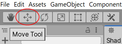
Figure 4.31 – The Move Tool
- Move the row of vertexes to make that subdivision of the plane thinner. You can use the checkered pattern on the terrain to get a notion of the size of the wall in meters:

Figure 4.32 – Moved vertexes
- Repeat steps 3 to 5 for each row of vertexes until you get wall outlines with similar sizes:

Figure 4.33 – Moved vertexes to reduce edge cell width
Important Note
If you want the vertexes to have exact positions, I recommend that you install and explore the ProGrids package. It is a position snapping system that works with regular Unity and ProBuilder.
Now that we have created the outline for our walls, let's add new faces to our mesh to create them. In order to use the subdivisions or "Faces" we have created to make our walls, we must pick and extrude them. Follow these steps to do so:
- Select the plane.
- Select the fourth button of the ProBuilder buttons in the Scene view:

Figure 4.34 – Select Face tool
- While holding Ctrl (command on Mac), click over each of the faces of the wall outlines:

Figure 4.35 – Edge faces being selected
- In the ProBuilder window, look for the plus icon (+) to the right of the Extrude Faces button. It will be located in the red section of the window:

Figure 4.36 – Extrude Faces option
- Set Distance to 5 in the window that appeared after we clicked the plus button.
- Click the Extrude Faces button in that window:

Figure 4.37 – Extrude distance option
- Now, you should see that the outline of the walls has just raised up from the ground:

Figure 4.38 – Extruded grid edges
Now, if you pay attention to how the base floor and walls touch the terrain, there's a little gap. We can try to move the base downward, but the floor will probably disappear because it will be buried under the terrain. A little trick we can do here is just push the walls downward, without moving the floor, so that the walls will be buried in the terrain but our floor will keep a little distance from it. You can see an example of how it would look in the following figure:
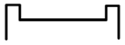
Figure 4.39 – Slice of expected result
In order to do so, we need to do the following:
- Select the third ProBuilder button in the Scene view to enable edge selection:

Figure 4.40 – Select edges tool
- While holding Ctrl (command on Mac), select all the bottom edges of the walls.
If you selected undesired edges, just click them again while holding Ctrl (command on Mac) to deselect them, all while keeping the current selection:

Figure 4.41 – Selecting floor edges
Information Box
If you want to use the Wireframe mode in the previous screenshot, click on the Shaded button in the top-left part of the Scene view and select the Wireframe option from the drop-down menu.
- Enable the Move Tool pressing the second button in the top-left part of the Unity Editor:
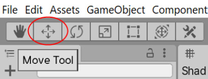
Figure 4.42 – The Move Tool
- Move the edges downward until they are fully buried under the terrain:

Figure 4.43 – Overlapping faces
Now that we have a base mesh, we can start adding details to it using several other ProBuilder tools.
Adding details
Let's start adding details to the base by applying a little bevel to the walls. Follow these steps:
- Using the edge selection mode (the third button of the ProBuilder buttons), select the top edges of our model:

Figure 4.44 – Top wall edges being selected
- In the ProBuilder window, click on the plus icon to the right of the Bevel button.
- Set a distance of 0.5:

Figure 4.45 – Bevel distance to generate
- Click on Bevel Edges. Now, you can see the top part of our walls with a little bevel:

Figure 4.46 – Result of the bevel process
- Optionally, you can do that with the bottom part of the inner walls:

Figure 4.47 – Bevel being applied to floor-wall edges
Another detail to add could be a pit in the middle of the ground as a hazard we need to avoid falling into and to make the enemies avoid it using AI. In order to do that, follow these steps:
- Enable the FACE selection mode by clicking the fourth ProBuilder Scene view button.
- Select the floor.
- Click the Subdivide faces option in the ProBuilder window. You will end up with the floor split into four.
- Click that button again to end up with a 4 x 4 grid floor:

Figure 4.48 – Subdividing the floor
- Select the four inner floor tiles.
- Enable the Scale Tool by clicking the fourth button in the top-left part of the Unity Editor:

Figure 4.49 – Scale Tool
- Using the gray cube at the center of the gizmo, scale down the center tiles:

Figure 4.50 – Inner cells being shrunk
- Click the Extrude Faces button in the ProBuilder window.
- Push the extruded faces downward.
- Right-click on the ProBuilder window tab and select Close Tab. We need to get back to terrain editing and having ProBuilder open won't allow us to do that comfortably:

Figure 4.51 – Close Tab option
- Select the Terrain and lower that area of the terrain so that we can see the pit:
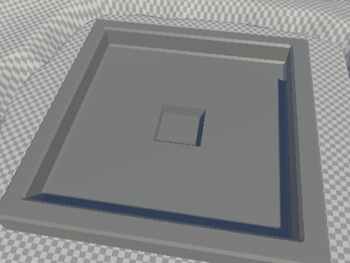
Figure 4.52 – Terrain being lowered for the pit to be visible
I know we didn't plan the pit in the original level layout, but remember that the define acronym is a document that will constantly change in the middle of game development, so sometimes, we can be bold and change it in order to improve the game. Just take care to not go too far with never ending changes, which is a difficult-to-master art.
Summary
In this chapter, we learned how to create large Terrain meshes using Height Maps and Unity Terrain tools such as Paint Height and Set Height to create hills and river basins. Also, we saw how to create our own 3D meshes using ProBuilder, as well as how to manipulate the vertexes, edges, and faces of a model to create a prototype base model for our game. We didn't discuss some performance optimizations we can apply to our meshes or some advanced 3D modeling concepts as that would require entire chapters and that's outside the scope of this book. Right now, our main focus is prototyping, so we are fine with our level's current status.
In the next chapter, we will learn how to download and replace these prototyping models with final art by integrating Assets (files) we have created with external tools. This is the first step to improving the graphics quality of our game so that it reaches the final look, which we will finish by the end of Part 2.