This chapter illustrates all the input and output nodes available in Blender Compositor, essential for importing or exporting data from it. The following is the list of topics covered in this chapter:
- Input nodes
- Output nodes
Input nodes are used to import footage into the Node Editor. Output nodes are used to export or display the result of a node graph. So, these nodes form the head and tail of the node flow drawn in Blender's node graph UI.
Input nodes are used to generate footage or to feed footage into the flow. These nodes don't have any input sockets. At any instance, there will be multiple types of inputs that a node flow might require, as shown in following screenshot and listed as follows:
- A color or value
- A procedurally generated pattern or texture
- A rendered static or sequence of images
- A movie clip
- Data rendered through the active camera of the current scene
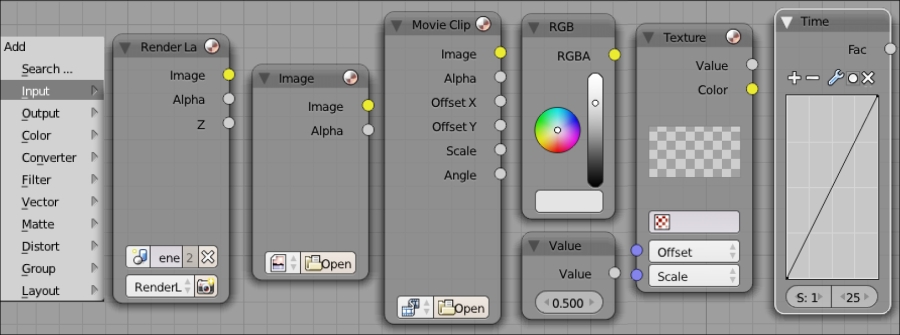
The Render Layers node inputs the rendered data through the active camera of the current scene. As shown in following screenshot, the node displays all the available passes, render layers and scenes present in the current rendered file. Multiple Render Layers nodes can be used to pick different layers or scenes from the rendered data of the current Blender file:

The Image node loads images or image sequences into the Node Editor, exposing all channels of the image. This node can also input the Alpha and Z depth channels, if the image contains them. An image that's loaded in the UV Image Editor can also be picked using this node. Dragging and dropping an image into the Node Editor automatically loads the image into the Image node. When OpenEXR Multilayer is chosen as the format for a render image in render settings, all enabled render passes are stored in the same image. After rendering, this image can be dragged on to the Node Editor; Blender imports the image using the Image node, with all passes saved in their respective buffers.
The Movie Clip node can load any movie file supported by Blender. The open folder icon is used to browse the required clip.
The RGB node loads a fixed color. The color can be chosen from the color wheel and a vertical value bar seen on the node. Alternatively, a bigger color wheel can be obtained by clicking on the colored rectangle at the bottom of the node. This value can be inserted to animate the image by right-clicking on it and clicking on Insert Keyframe.
Similar to the RGB node, the Value node loads a constant value to the flow. The Value slider provided at the bottom of the node can be used to attain the required value. A value can be manually entered by left-clicking the slider or by left-clicking on it, holding, and dragging the values. This value can be keyed to animate by right-clicking on it and clicking on Insert Keyframe.
The Texture node can load any texture that's available in the current Blender file or from Blender's procedural texture library, as shown in following screenshot:
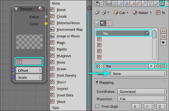
The Color socket outputs the RGB channel of the texture and the Value socket outputs the Luminance channel of the texture. The Offset and Scale parameters can be used to modify the texture. This modification will not affect the texture itself.
The Time node also loads a value similar to a value node, but the difference is that this value can be altered over time using the curve. The start and end frames will signify the frames in which the curve affects the flow.
The Mask node can be used to create shape masks by picking mask's data blocks in the browse ID data block. These mask's data blocks can be created in the UV Image Editor by choosing the Mask mode as the editing context, shown in following screenshot. These masks, generated using the Mask node, can be used in the compositing flow to modify the pixels inside or outside the mask shape.

The Bokeh Image node can be used to create a custom bokeh shape. This shape can be connected to the Bokeh Blur node, which then uses this shape as the bokeh shape, as shown in following screenshot:
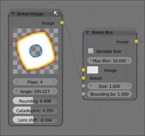
The description of the node is as follows:
- Flaps control the number of sides of the bokeh shape
- Angle rotates the bokeh shape
- Rounding reduces the sharpness at the corners of the sides
- Catadioptric creates and increases empty pixels from inside the bokeh shape
- Lens Shift adds a chromatic aberration effect to the shape, splitting the shape with color offsets
Output nodes should be used to fetch data from the compositor and to view it in the UV / Image Editor or save it as an image or image sequence. Different output nodes are shown in following screenshot:
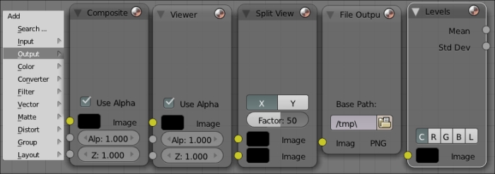
The Composite node connects the output of a composite flow to the renderer. Connecting a node to the Composite node will output the result till the connected node, when rendered. Leaving the Composite node unconnected will output a blank image. Having multiple composite nodes might give unpredictable results.
The Image, Alpha, and Z input sockets store the corresponding connected results into the respective image channels. The Z input can be used only if the EXR format is chosen as the output format. This node can also be used to route the output to the UV / Image Editor.
The Viewer node is a handy tool to inspect the compositing flow. Using this node, the output can be tunneled to backdrop of the Node Editor or the UV / Image Editor.
The Split Viewer node allows you to inspect two images or two parts of the compositing flow. Clicking on X will display a side-by-side comparison and clicking on Y will display a top-down comparison. The image connected to the top socket is displayed either on the right or on top of the window. The slider provides an adjustment to the location of the split between the two sockets in the viewer.
The File Output node can simulate AOVs (arbitrary output values) from the compositing flow, similar to rendering passes from a render layer. Connecting this node to any other node will write an image from the calculations done till the connected node.