
C
ARDUINO PRIMER

Arduino microcontroller boards are perfectly suited to a postapocalyptic world. They’re robust, they’re reliable, and they use very little power. If you’re new to Arduino, this appendix will get you started with this great little board so you can begin to make your end-of-the-world preparations now and greatly enhance your chances of survival.
WHAT IS AN ARDUINO?
There are various types of Arduino board, but by far the most common is the Arduino Uno, and this is the one used for all the projects in this book (see Figure C-1).
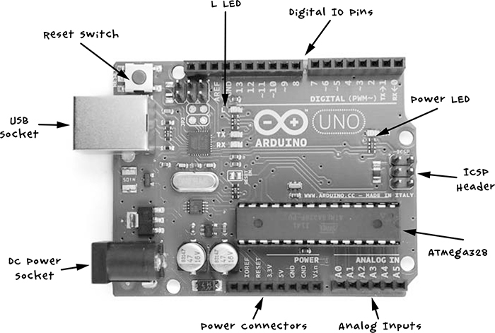
Figure C-1: An Arduino Uno R3
The Arduino Uno shown in Figure C-1 is a revision 3 (R3) board, which is the latest at the time of writing. We’ll have a look at each of the components and their uses.
Let’s start our tour with the USB socket. This serves several purposes: it can be used to provide power to the Arduino or to connect the Arduino to your computer for programming. It can also serve as a communications link to other computers, as in “Project 13: A Raspberry Pi Control Center” on page 140 where it sends data from the Arduino to a Raspberry Pi. The little red button on the Arduino is the Reset button. Pressing it will cause the program that is installed on the Arduino to restart.
The connection sockets along both the top and bottom edges of the Arduino are where you attach electronics. On the top side of Figure C-1 are digital input and output pins, numbered 0 to 13 and configurable as either inputs or outputs. Inputs read messages coming in; for example, if you connect a switch to a digital input, the input will detect whether the switch is pressed. Outputs send information or power out; if you connect an LED to a digital output, you can turn it on by switching the output from low to high. In fact, one LED, called the L LED, is built onto the board and connected to digital pin 13.
On the right, the power LED indicates whether the board is powered. The ICSP (In-Circuit Serial Programming) header is only for advanced programming of the Arduino, and most casual users of Arduino will never use it.
The ATMega328 is a microcontroller integrated circuit (IC) and the brains of the Arduino. The chip contains 32KB of flash memory, where you store the program you want the Arduino to run.
On the bottom right of Figure C-1 is a row of analog input pins labeled A0 to A5. Digital inputs can only tell whether something is on or off, but analog inputs can actually measure the voltage at the pin, as long as the voltage is between 0V and 5V. Analog input pins could be used, for example, to measure voltage from a temperature sensor like the one used in “Project 12: Temperature Alarm” on page 131.
The final row of sockets provides miscellaneous power connections. In “Project 4: Battery Monitor” on page 53, we use Vin (volts in) to provide power to the Arduino; 5V and GND (or ground), which means 0V, are also power connections that you will need when connecting external electronics.
At the bottom left, we have a DC power jack, which is another power connection. This can accept anything between 7V and 12V DC. The Arduino will automatically accept power from the USB socket and power from the DC connector or Vin socket, too.
ARDUINO SOFTWARE
The Arduino might not be what you would expect from a computer. It has no operating system and no keyboard, monitor, or mouse. This is, of course, good news for the survivor who needs to travel light. And while you can reprogram an Arduino as many times as you like, it also only ever runs a single program (called a sketch) at a time. To program the Arduino, you must have the Arduino IDE software installed on your normal computer, so we’ll first cover installation and then talk about writing programs.
INSTALLING THE ARDUINO IDE
The Arduino IDE is easy to use, making it one major reason for the Arduino’s great popularity. It is available for Windows, Mac, and Linux computers, and it programs the Arduino over a USB connection without any need for special programming hardware.
NOTE
You will need an Internet connection to download the Arduino IDE, so do this before you start hearing about zombies on the news!
To install the Arduino IDE for your platform, download the software from the Arduino site at http://www.arduino.cc/ (click Download at the top and install the version that’s appropriate for your system). Then follow the instructions from the Getting Started link. Windows and Mac users will need to install USB drivers for the Arduino IDE to be able to communicate with the Arduino.
Once you have everything installed, run the Arduino IDE. Figure C-2 shows the Arduino IDE window with some code in it.

Figure C-2: The Arduino IDE window
The Upload button, as the name suggests, uploads the current sketch to the Arduino board. Before uploading, however, it converts the textual programming code into executable code for the Arduino and displays any errors in the Log area. The Verify button checks the code for errors without uploading the program to the board.
The serial monitor button opens the serial monitor window, which is used for two-way communication between the Arduino and another computer, as in “Project 13: A Raspberry Pi Control Center” on page 140. You can type in text messages to send to the Arduino, and you should see any responses that come back in the same window. The Status area at the bottom of the screen gives information on the type of Arduino you’re using and the corresponding serial port that will be programmed when the Upload button is pressed. The Status area in Figure C-2 also shows the type of port you would expect to see when using a Mac or Linux computer (something like /dev/cu.usbmodem411). If you’re using a Windows computer, this will display COM followed by a number.
The large, white area of the IDE is the Program Area, where you type the program code you want uploaded to the Arduino.
The File menu allows you to Open and Save sketches as you would in a word processor, and it has an Examples submenu from which you can load example sketches.
UPLOADING A SKETCH
To test out your Arduino board and make sure the Arduino IDE is properly installed, click File ▸ Examples ▸ 01. Basics to open the example sketch called Blink (shown in Figure C-2).
Use a USB cable to attach your Arduino to your computer. The power LED of the Arduino should light up as it’s plugged in, and a few other LEDs should flicker as well.
Now that the Arduino is connected, you need to tell the IDE the type of board being programmed and the serial port it’s connected to. Set the board using the menu Tools ▸ Board and then select Arduino Uno from the list of boards.
Set the serial port using the menu Tools ▸ Port. If you’re using a Windows computer, you probably won’t have many options there; you may find only the option COM4. On a Mac or Linux computer, there are generally more serial connections listed, many of which are internal devices, and it can be difficult to work out which one refers to your Arduino board.
Usually, the correct port is one that starts dev/ttyusbmodemNNNN, where NNNN is a number. In Figure C-3, the Arduino attached to my Mac has been selected.

Figure C-3: Selecting the Arduino serial port
If your Arduino doesn’t show up in the list, this usually means you have a problem with the USB drivers, so try reinstalling them. If you’re a Windows user, try rebooting.
You should now be ready to upload the sketch to the Arduino, so press the Upload button. Messages should appear in Log area, and then the TX and RX LEDs on the Arduino should flicker as the program is uploaded onto the board.
When the upload is complete, you should see a message like the one shown in Figure C-4.

Figure C-4: A successful upload
The Done uploading message tells you that the sketch has uploaded, and the last line in the console tells you that you’ve used 1,084 bytes of the 32,256 bytes available on your Arduino.
Once the sketch is uploaded, the built-in L LED on the Arduino should blink slowly on and off, which is just what the Blink program is expected to do.
INSTALLING THE ANTIZOMBIE SKETCHES
All the sketches for the book are available via the book’s website (http://www.nostarch.com/zombies/). Click on the Download Code link to download a ZIP file called zombies-master.zip. Make sure to do this before the apocalypse begins, because your broadband is likely to be a low priority once the infection has begun to spread. This folder will contain all the Arduino and Raspberry Pi programs for the projects in this book.
Install the Arduino sketches so that you can use them directly from your Arduino IDE by copying the subfolders from the Arduino folder into Documents/Arduino folder for Mac and Linux users and My DocumentsArduino for Windows users. Exit and reopen the Arduino IDE. Now when you view File ▸ Sketchbook, you should find all the book’s sketches listed.
ARDUINO PROGRAMMING BASICS
This section contains an overview of the main Arduino programming commands to help you understand the sketches used to do with zombies. If you’re interested in learning the Arduino C programming language, consider getting a copy of my book Programming Arduino: Getting Started with Sketches (Tab Books, 2012). The technical reviewer for the book you’re reading now (Jeremy Blum) has also written a very good book on Arduino and has produced a superb series of video tutorials. You can find links to all this from his website (http://www.jeremyblum.com/).
STRUCTURE OF AN ARDUINO SKETCH
All Arduino sketches must have two basic functions (units of program code that perform a task): setup and loop. To see how they work, let’s dissect the Blink example that we looked at earlier.
int led = 13;
// the setup routine runs once when you press reset
void setup() {
// initialize the digital pin as an output
pinMode(led, OUTPUT);
}
// the loop routine runs over and over again forever
void loop() {
digitalWrite(led, HIGH); // turn the LED on (HIGH is the voltage level)
delay(1000); // wait for a second
digitalWrite(led, LOW); // turn the LED off by making the voltage LOW
delay(1000); // wait for a second
}
Your Blink sketch might be slightly different if you have a newer version of the Arduino IDE, so for the purposes of this discussion, refer to the sketch printed here rather than the one loaded in your IDE.
The text preceded by a double slash (//) is called a comment. It’s not executable program code but rather a description of what’s happening at that point in the sketch.
Just after the words setup() and loop(), we have a { symbol. (Sometimes this is put on the same line as the preceding word and sometimes on the next line. Where it goes is just a matter of personal preference and has no effect on the running of the code.) The { symbol marks the start of a block of code, which ends with a corresponding } symbol. You’ll use curly brackets to group together all lines of code that belong to a particular function or other control structure.
The lines of code inside the setup function run just once, when power is applied to the Arduino or the Reset button is pressed. You use setup to perform all the tasks that need doing just once when the program starts. In Blink, the code inside the setup function just sets the LED pin as an output.
The commands inside the loop function will be run over and over again; in other words, when the last line inside loop has run, the first line will start again.
Now, let’s parse this sketch, starting from the top line.
CREATING VARIABLES AND CONSTANTS
Variables are a way of giving names to values; for example, the first line of Blink labels pin 13 led:
int led = 13;
This defines an int variable called led and gives it an initial value of 13, because 13 is the number of the Arduino pin that the L LED is connected to. The word int is short for integer and means that this variable returns a whole number without decimals.
In some of the book’s other sketches, variables like this, that define a specific pin to be used, are preceded by a const keyword:
const int led = 13;
The const keyword tells the Arduino IDE that the value of led is never going to change from 13, making it a constant. Assigning values this way results in slightly smaller and quicker sketches and is generally considered a good habit.
CONFIGURING DIGITAL OUTPUTS
The Blink sketch also shows a good example of a setting a pin up to be a digital output. Pin 13, having been defined as led, is configured as an output in the setup function by this line:
pinMode(led, OUTPUT);
As this only needs to be done once, it is placed inside the setup function. Once the pin is set as an output, it will stay an output until we tell it to be something else.
For it to blink, the LED needs to turn on and off repeatedly, so the code for this goes inside loop:
digitalWrite(led, HIGH); // turn the LED on (HIGH is the voltage level)
delay(1000); // wait for a second
digitalWrite(led, LOW); // turn the LED off by making the voltage LOW
delay(1000); // wait for a second
The command digitalWrite takes two parameters (pieces of data that the function needs to run), which are passed to the function inside parentheses and separated by a comma. The first parameter defines which Arduino pin to write to (in this case, pin 13, as specified by led), and the second parameter gives the value to be written to the pin. A value of HIGH sets the output to 5V, turning the LED on, and a value of LOW sets the pin to 0V, turning the LED off.
The delay function holds the parameter that defines how long the Arduino should continue with its current function. In this case, a value of 1000 delays the program for one second before changing the state of the LED.
CONFIGURING DIGITAL INPUTS
Digital pins can also be set as input pins using the pinMode command. The Blink sketch doesn’t do this, so here’s an example:
pinMode(7, INPUT)
This pinMode function sets pin 7 as an input. Just as with an output, you’ll rarely need to change the mode of a pin, so define input pins in the setup function.
Having set the pin as an input, you can then read the voltage at that pin, as in this example loop function:
loop()
{
if (digitalRead(7) == HIGH)
{
digitalWrite(led, LOW)
}
}
Here, the LED will be turned off if the input at pin 7 is read as HIGH at the time it is tested. The Arduino decides whether to turn the LED on with an if statement, which starts with the if command. Immediately after the word if is a condition. In this case, the condition is (digitalRead(7) == HIGH). The double equal sign (==) tells the machine to compare the two values on either side. In this case, if pin 7 is HIGH, then the block of code surrounded by { and } after the if will run; otherwise it won’t. We have already met the code to be run if the condition is true. This is the digitalWrite command to turn the LED on.
NOTE
Lining up the { and } makes it easier to see which } belongs to which {.
STABILIZING DIGITAL INPUTS WITH PULL-UP RESISTORS
The preceding example code in assumes that the digital input is definitely either high or low. A switch connected to a digital input can only close a connection. You’ll typically connect switches in such a way that when flipped, the digital input is connected to GND (0V). While the switch’s connection is open, the digital input is said to be floating. That means the input isn’t electrically connected to anything, but a floating input can still pick up electrical noise from the circuitry around it, causing the voltage on the pin to oscillate between high and low.
This behavior is undesirable because the code could be activated unexpectedly. To prevent input pins from floating, just add a pull-up resistor (Figure C-5). We use just such a resistor in “Project 6: PIR Zombie Detector” on page 72.
When the switch is open (as shown in Figure C-5), the resistor connects the input pin to a voltage source, pulling up the voltage at the input pin to 5V and holding it there. Pressing the button to close the switch overrides the weak pulling up of the input, connecting the digital input to GND instead.

Figure C-5: Schematic for using a pull-up resistor with a digital input
Arduino inputs have built-in pull-up resistors of about 40 kΩ that you can enable as follows:
pinMode(switchPin, INPUT_PULLUP);
This example shows how you would set the pin mode of a digital input to be used with a switch using the Arduino pull-up resistor: just set the pin mode to INPUT_PULLUP rather than INPUT.
READING ANALOG INPUTS
Analog inputs allow you to measure a voltage between 0V and 5V on any of the A0 to A5 analog input pins on the Arduino. Unlike with digital inputs and outputs, you don’t need to include the pinMode command in setup when using an analog input.
You use analogRead to read the value of an analog input, and you supply the name of the pin you want to read as a parameter. Unlike digitalRead, analogRead returns a number rather than just true or false values. The returned number will be between 0 (0V) and 1,023 (5V). To convert the number into an applicable voltage, multiply the value by 5 and then divide it by 1,023, which amounts to dividing it by 204.6.
Here’s how you’d read an analog value and convert it in Arduino code:
int raw = analogRead(A0);
float volts = raw / 204.6;
The variable raw is an int (whole number) because the reading from an analog input is always a whole number. To scale the raw reading as a decimal number, the variable needs to be a float (floating point) type of variable.
WRITING TO ANALOG OUTPUTS
Digital outputs only allow you to turn a component (like an LED) on and off, but analog outputs allow you to control the level of power supplied to a component incrementally. This control allows you to, for example, control the brightness of an LED or the speed of a motor. This is used in “Project 20: Silent Haptic Communication with Arduino” on page 209 to reduce the power to the motor so that it doesn’t attract zombies by making too much noise.
Only the pins D3, D5, D6, D9, D10, or D11 are capable of being used as analog outputs. These pins are marked with a little tilde (~) beside the pin number on the Arduino.
To control an analog output, use the command analogWrite with a number between 0 and 255 as the parameter, as in the following line:
analogWrite(3, 127);
A value of 0 is 0V and fully off, while a value of 255 is 5V and fully on. In this example, we set the output of pin D3 to 127, which would be half power.
REPEATING CODE IN CONTROL LOOPS
Control loops (not to be confused with the loop function) allow you to repeat an action a set number of times or until some condition changes. There are two commands you can use for looping: for and while. You would use the for command for repeating something a fixed number of times and while for repeating something until a condition changes.
The following code makes an LED blink 10 times and then stops:
void setup() {
pinMode(led, OUTPUT);
for (int i = 0; i < 10; i++)
{
digitalWrite(led, HIGH);
delay(1000);
digitalWrite(led, LOW);
delay(1000);
}
void loop() {
}
It is tempting to think of an analog output as being capable of a voltage between 0V and 5V, and if you attach a voltmeter between an analog output pin and GND, the voltage will indeed seem to take on values between 0V and 5V as you change the parameter to analogWrite. In fact, things are a little more complex than that. This kind of output is using pulse width modulation (PWM). Figure C-6 shows what is really going on.

Figure C-6: Analog output’s pulse width modulation
An analog output pin generates 490 pulses per second with varied pulse widths. The larger the proportion of the time that the pulse stays high, the greater the power delivered to the output, and hence the brighter the LED or faster the motor.
A voltmeter reports this as a change in voltage because the voltmeter cannot respond fast enough and therefore does a kind of averaging (integration).
In this example, we place the blinking code in setup rather than loop, because loop would repeat the blink cycle immediately so the LED would not stop after 10 times.
If you wanted to keep an LED blinking as long as a button connected to a digital input was pressed, you would use a while command:
➊ while (digitalRead(9) == LOW)
{
digitalWrite(led, HIGH);
delay(1000);
digitalWrite(led, LOW);
delay(1000);
}
This code says that while pin 9 detects that a button is being pressed ➊, the LED should be lit.
SETTING TWO CONDITIONS WITH IF/ELSE
In “Configuring Digital Outputs” on page 251, we used an if command to tell the Arduino IDE to do something if a certain condition was met. You can also use if in conjunction with the else command to instruct the IDE to perform one set of code if the condition is true and a different set of commands if it is false. Here’s an example:
if (analogRead(A0) > 500)
{
digitalWrite(led, HIGH);
}
else
{
digitalWrite(led, LOW);
}
This if statement turns the led pin on if an analog reading is greater than 500 or off if the reading is less than or equal to 500.
MAKING LOGICAL COMPARISONS
So far we have used two types of comparison: == (equal to) and > (greater than). Here are some more comparisons you can make:
<= less than or equal to
>= greater than or equal to
!= not equal to
You can also make more complicated comparisons using logical operators like && (and) and || (or). For example, to turn an LED on if a reading is between 300 and 400, you could write the following:
int reading = analogRead(A0);
if ((reading >= 300) && (reading <= 400))
{
digitalWrite(led, HIGH);
}
{
digitalWrite(led, LOW);
}
In English, this code might read, “If the reading is greater than or equal to 300 and the reading is less than or equal to 400, then turn the LED on.” Since we’re using the && operator to specify that both conditions must be true, if either condition is not met, the LED remains dark.
GROUPING CODE INTO FUNCTIONS
Functions can be confusing if you’re new to programming. Functions are best thought of as ways to group together lines of code and give them a name so that the block of code is easy to use over and over again.
Built-in functions such as digitalWrite are more complicated than they first seem. Here is the code for the digitalWrite function:
void digitalWrite(uint8_t pin, uint8_t val)
{
uint8_t timer = digitalPinToTimer(pin);
uint8_t bit = digitalPinToBitMask(pin);
uint8_t port = digitalPinToPort(pin);
volatile uint8_t *out;
if (port == NOT_A_PIN) return;
// If the pin that support PWM output, we need to turn it off
// before doing a digital write.
if (timer != NOT_ON_TIMER) turnOffPWM(timer);
out = portOutputRegister(port);
uint8_t oldSREG = SREG;
cli();
if (val == LOW) {
*out &= ~bit;
} else {
*out |= bit;
}
SREG = oldSREG;
}
Since someone already wrote the digitalWrite function, we don’t have to worry about what all this code does; we can just be glad that we don’t have to type it all out every time we want to change pin from high to low. By giving that big chunk of code a name, we can just call the name to use this code.
You can create your own functions to use as shortcuts for more complicated chunks of code. For example, to create a function that makes an LED blink the number of times you specify as a parameter, with the LED pin also specified as a parameter, you could use the sketch below. This function is named blink, and you can call it during startup so that the Arduino L LED blinks five times after a reset.
➊ const int ledPin = 13;
➋ void setup()
{
pinMode(ledPin, OUTPUT);
➌ blink(ledPin, 5);
}
void loop() {}
➍ void blink(int pin, int n)
{
➎ for (int i = 0; i < n; i++)
{
digitalWrite(ledPin, HIGH);
delay(500);
digitalWrite(ledPin, LOW);
delay(500);
}
}
At ➊, we define the pin being used. The setup function at ➋ sets ledPin as an output and then calls the function blink ➌, passing it the relevant pin and the number of times to blink (5). The loop function is empty and does nothing, but the Arduino IDE insists that we include it even if it serves no purpose. If you don’t include it, you will get an error message when you install the program.
The blink function itself begins at ➍ with void. void indicates that the function does not return any value, so you cannot assign the result of calling that function to a variable, as you might want to do if the function performed some kind of calculation. Then follows the name of the function (blink) and the parameters the function takes, enclosed within parentheses and separated by commas. When you define a function, you must specify the type of each of the parameters (for example, whether they are int or float). In this case, both the pin (pin) and the number of times to blink (n) are int values. Lastly, at ➎, we have a for loop that repeats the digitalWrite and delay commands inside it n times.
That’s it for the software crash course. If you want to learn more about programming for Arduinos, visit http://www.arduino.cc/ before everyone at your Internet service provider becomes a zombie.
ASSEMBLING A SCREWSHIELD
Many of the projects in this book use a screwshield that fits over the Arduino sockets and allows you to connect wires to Arduino pins using screw terminals. Not all wires will fit into the normal Arduino sockets, but almost any thickness of wire will fit securely in a screw terminal and won’t come loose. There are various screwshields on the market, all with slightly different layouts. In this book, I use the popular model from Adafruit (the proto-screwshield, part number 196), which is provided as a kit that you have to solder together. There are lots of connections to make, but none of them are difficult. The component parts of the proto-screwshield are shown in Figure C-7.

Figure C-7: The parts of Adafruit’s Proto-Screwshield
The screw terminals line the edge of the board and Arduino pass-through headers. The screwshield pass-through headers slot through the shield into the PCB. You can plug wires into these as you would in the Arduino Uno, and they have sockets on the top side so you can plug still another shield on top.
Of the two LEDs, one is a power LED that indicates when the board is powered up, and the other is for you to use in your build. You don’t have to solder either LED in place if you don’t need them. The push button is a reset switch, which can be useful as it’s hard to get at the Arduino’s reset button when the screwshield is in place. Again, it is by no means essential.
Figure C-8 shows the board being assembled.

Figure C-8: Assembling the screwshield
To assemble the screwshield, follow these steps:
1. Solder the LEDs, resistors, and switch (assuming you want them) in place (Figure C-8a).
2. Put all the screw terminals in place along the outermost edges of the screwshield (Figure C-8b) and flip the board over to solder them on the underside of the PCB. Make sure they are the right way around so that the openings where the wires enter are facing outward, away from the board.
3. Push the pass-through headers through from the top of the board (Figure C-8c) and solder them. Notice that there are two rows of holes on each side of the board where they are able to go; place them in the outer sets of holes. The inner sets are used to wire things up to the pins on the central prototyping area of the board.
If you need a refresher on how to solder to a PCB, review “Soldering Basics” on page 230. With your components in place, make sure your solder joints look sound (also described in “Soldering Basics”). You should be ready to deploy this handy shield in all of your antizombie base defense endeavors and conserve precious solder for devices you intend to last a long time.
FURTHER RESOURCES
There are many great online resources and books that will tell you more about how to use the Arduino in your projects. Here are a few links to get you started:
• I have written a number of books on Arduino, including Programming Arduino: Getting Started with Sketches (Tab Books, 2012) and various Arduino project books. You can find a full list of my books at http://www.simonmonk.org/.
• Jeremy Blum, the technical editor of this book, has made a great series of introductory videos on the Arduino, which you can find here: https://www.youtube.com/playlist?list=PLA567CE235D39FA84.
• Jeremy also has written a great book on Arduino, called Exploring Arduino (Wiley, 2013).
• I have written a series of online Arduino lessons, the Adafruit “Learn Arduino” series, which you can find here: https://learn.adafruit.com/series/learn-arduino/.