
B
BASIC SKILLS

If you’re going to be a postapocalyptic maker and survive the land of the walking dead, then you’ll need a few key electronics skills. This appendix is a quick guide to the basics, such as joining wires together, soldering, and using a multimeter. Flip here anytime you need a refresher. It may save your life!
STRIPPING WIRES
For an apocalypse survivor, stripping the insulation off wires is a skill that belongs near the top of the list. The devices in this book will help you stay alive, and to build them, you’ll often need to join insulated wires together or fit them into a screw terminal. The first step in that process is exposing the bare wire.
To strip a wire, use a blunt pair of pliers to grip the wire and pull off the insulation with a sharp pair of wire cutters (also called snips). Figure B-1 shows the process.

Figure B-1: Stripping wires
Grip the wire with pliers (Figure B-1a). If your wire is long, you could wrap it around your fingers instead. Either way, the idea is to stop the wire from moving. Next, gently pinch the wire with the cutters at the position where you want to remove the insulation. Apply just enough pressure to almost cut through the insulation without cutting into the wire inside, then pull the insulation away (Figure B-1b). If the snips start to slip as you pull, just squeeze them a bit tighter.
Mastering this skill can take a while, so practice on some old wire before you try it on something important. If you cut the last good wire in your cache too short, you could find yourself unable to complete your latest antizombie invention until the next supply run—when it might be too late.
JOINING WIRES BY TWISTING
Knowing how to twist wires together is a useful skill, too, especially if you haven’t come across any solder in your scavenging trips. If done properly (as illustrated in Figure B-2), just twisting the wires together can make pretty good electrical connections.

Figure B-2: Joining wires by twisting
First, strip about half an inch (15 mm) of insulation off each wire (see “Stripping Wires” on page 227). Then, if your wire is stranded rather than solid, use your thumb and forefinger to twist each wire on its own and keep all the strands together (Figure B-2a). Next, place the two wires side by side, lining up the ends of the insulation, and twist the wires around each other (Figure B-2b). Try to make sure that the wires actually go around each other, rather than leaving one wire straight while the other wraps around it. This can be difficult if the wires are of different thicknesses.
Finally, coil the intertwined wires into a tight ball (Figure B-2c) and wrap the whole thing in electrical tape or heatshrink tubing (see “Using Heatshrink” on page 235). You can also use pliers to really tighten up the joint.
If you have soldering equipment, then you can make the connection mechanically stronger and more electrically reliable by heating the little knot with a soldering iron and feeding solder into it, as I describe in the next section.
If you want to know how NASA does it, take a look at this link: http://makezine.com/2012/02/28/how-to-splice-wire-to-nasa-standards/.
SOLDERING BASICS
Soldering is much easier than it looks, and you don’t need to spend a lot of money on a fancy soldering station. During an apocalypse, your options will be limited, but a basic starter kit (see Figure B-3) will work just fine.
You can find basic soldering kits at an auto parts store or even at some hardware stores. If you are buying in advance of the apocalypse, then Adafruit sells a great starter kit (product 136) that also includes a multimeter, hookup wire, and various other useful bits and bobs.

Figure B-3: A basic soldering kit
There are lots of accessories and tools that can make soldering quicker, but these are by no means essential. Here’s all you really need:
A soldering iron Look for an iron with a power rating of 30W or more, with a fine tip (say 1/25 inch, or 1 mm). Before the zombie apocalypse, just buy one that’s AC powered. To prepare, you could also buy a soldering iron that runs on 12V DC and keep it with your emergency supplies; that way, you’ll have an iron you can power from a car battery. These soldering irons, intended for working on the electrical components of cars, are quite common.
Solder If you buy a soldering kit, it will probably come with a coil of solder. Solder comes in two flavors: leaded and lead-free. Leaded solder melts at a lower temperature and is generally easier to use than lead-free solder. But please don’t eat either, no matter how desperate your food situation becomes.
Snips You’ll need a good pair of wire cutters to cut wires close to the surface of a PCB and for stripping wire.
A damp sponge or cloth Any old sponge will do. You’ll use it to wipe the tip of the iron when there’s excess solder.
WARNING
Soldering irons get hot. In fact, they get really hot, much hotter than the maximum temperature of your kitchen oven. So it goes without saying that if you touch the hot end of a soldering iron, you’ll get a serious burn. This is not an activity for unsupervised children. Similarly, lead is a toxic element that is not at all good for you, so you may prefer to use lead-free solder, despite it being a little harder to work with.
JOINING WIRES WITH SOLDER
To join together two wires with solder, start by following the instructions in “Joining Wires by Twisting” on page 229. Then, you can solder the joint. The trick with soldering is to always make the solder flow into the thing you’re soldering; Figure B-4 shows solder flowing into the ball of wires from Figure B-2c.
Many beginners make the mistake of creating a blob of solder on the tip of the iron and then blobbing it onto the wire. This usually results in poor quality dry joints that may look okay but will fail quickly and, before they fall apart, may not make good contact with the wire. Therefore, you’ll want to heat the wire you want to solder before you touch the solder to it.

Figure B-4: Running solder into the joined wires
With that in mind, you can join your twisted wires as follows:
1. Turn your iron on and leave it to heat up. If your kit didn’t come with a stand for the soldering iron, make sure that you prop it somewhere safe so that the hot end is not touching anything.
2. Touch the end of the solder to the tip of the iron to see if it is hot. If it immediately melts and flows over the tip of the iron, then the iron is ready.
3. If the tip of the iron is not shiny and bright after this, then wipe it on a wet sponge. This makes a great sizzling noise! Repeat the previous step to tin the tip of the iron with solder. Tinning just means coating a wire or the tip of your iron with solder by heating it up and then pushing the solder onto it.
4. Press the tip of the soldering iron against the little knot of wires and leave it there for perhaps three or four seconds. Then, with the soldering iron still pressed to the knot, push the end of the solder onto the knot. The solder should flow into the knot. If your solder isn’t flowing well, it sometimes helps to feed a bit more solder to the joint, as solder contains cores of rosin flux, which helps the solder to liquefy.
5. Keep feeding the solder in until the whole knot of wires is coated in solder.
6. Remove the tip of your solder thread from the joint and replace the iron on its stand. Make sure that the wires don’t move while you give them 10 or 20 seconds to cool down.
You can also insulate your soldered connection with electrical tape or with heatshrink, as described in “Using Heatshrink” on page 235. If you plan to do this, then you can make a neater joint by soldering the wires side to side, without twisting them together (Figure B-5a–e).
After stripping the ends of the wires (Figure B-5a), tin them with solder (Figure B-5b). If the wire is stranded, the solder should flow between the strands that make up the wire.

Figure B-5: Soldering wires together without twisting them first
Now, lay the wires next to each other (Figure B-5c), heat the wires, and run solder into the valley they make (Figure B-5d). The end result should be a nice, even joined pair of wires (Figure B-5e).
SOLDERING A PCB
Wires are easier to scavenge than complete circuits, but being able to solder to a printed circuit board (PCB) will certainly serve you well during an apocalypse. For example, quite a few of the projects in this book use a screwshield that requires a bit of soldering to put together. Fortunately, the screwshield is a PCB with lots of convenient metal pads that are made for soldering. If you successfully followed the steps described in “Joining Wires with Solder” on page 231, then you shouldn’t have any problems soldering a PCB.
When attaching components to a PCB, the basic idea is that you push a component’s legs through from the top, flip the PCB over, solder the leads to their solder pads, and snip off the excess wire. Figure B-6 shows a component lead being soldered onto a screwshield.

Figure B-6: Soldering a component leg to a PCB
As with all soldering, the trick is to apply the solder to the thing being heated up rather than to the soldering iron, so heat the component leg and touch solder to it. You’ll often get the best results by giving the soldering iron a second or two to heat the component lead and solder pad before you apply the solder to the junction of the soldering iron tip and the component lead. Figure B-7 shows examples of two solder joints, one bad and one good.
The solder joint on the left is best described as “blobby,” and it’s a result of allowing a glob of solder to form on the tip of the iron and then “blobbing” it onto the PCB. The solder joint on the right is close to perfect. See how the whole pad is covered in solder, flowing all the way around the component lead and forming a very gentle little hill of a meniscus.
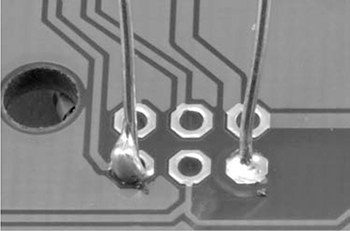
Figure B-7: Bad (left) and good (right) solder joints
USING HEATSHRINK
When you’re confident in your wire-connecting skills, try using heatshrink to insulate the wires. Heatshrink is a great way to finish a pair of wires that have been joined by twisting or soldering, and it’s a lot more durable than electrical tape. Wrapping the wires in electrical tape is fine at first, but eventually the tape starts to lose its stickiness and unravel. Heatshrink is also just more fun to use, and you’ll need all the fun you can get when zombies are the only ones knocking on your door.
Heatshrink comes as a tube that you can cut to the length you need. When heated with a hair dryer, hot air gun, or even a cigarette lighter, it shrinks to about half its diameter as if by magic. If your heatshrink starts out with a fairly snug fit over the wires, then it will grip the wires tightly after you heat it.
Here’s how to make a good connection and strengthen it with heatshrink:
1. Choose a heatshrink tube slightly wider than the joint you want to cover. Cut a sleeve long enough to cover the exposed wire and overhang onto the wire’s insulation a little bit.
2. If you’re connecting two wires that already have parts attached to their other ends, slide your heatshrink sleeve onto one wire before you solder them together, pushing the heatshrink as far away from the solder point as possible. I’ve lost count of the number of times I have soldered something together only to remember too late that the heatshrink then couldn’t be slid on. Every time that happens, I have to unsolder the wires again.
3. Join the wires using the end-to-end method described in “Joining Wires with Solder” on page 231. You’ll end up with something like Figure B-8a.

Figure B-8: Applying clear heatshrink tubing over joined wires
4. If you haven’t already done so, slide the heatshrink sleeve over the joint (Figure B-8b). The heatshrink I show is clear so you can see that the solder joint is good. Heatshrink is also commonly available in black and other colors.
5. Heat up the heatshrink with a hair dryer or even a match held underneath it (Figure B-8c). You don’t need to make it super hot. Just keep heating until you have a nice tight fit, as in Figure B-8d. But try not to scorch it!
Heatshrink comes in a huge range of diameters. If you plan to use it, I suggest buying a selection box that has short lengths of various diameters of heatshrink tubing. You can find these at auto parts stores, as heatshrink is often used when modifying or repairing car wiring.
USING A MULTIMETER
An electric current is a flow of electrons. But electrons are small—very small, in fact. So when it comes to working out what’s going on electrically, we need something that will allow us to measure what those pesky electrons are up to.
Where a doctor has a stethoscope to check the various pulse points in your body, an electronics enthusiast will use a multimeter (Figure B-9) to check specific points on a circuit.

Figure B-9: A multimeter
The multimeter shown in Figure B-9 cost about $5 but is still more accurate and has a wider range of features than an expensive multimeter from 20 years ago. Something like it should be perfectly good for any current, voltage, or resistance you need to measure to get ready for the zombie apocalypse.
A multimeter consists of a display at the top, a big rotary switch in the middle to select different measurement ranges, and some sockets at the bottom for attaching test leads. A multimeter should include test leads when you buy it. These are usually of the sort shown in Figure B-10a, but it can be very useful to also get some test leads that have alligator clips on the end (Figure B-10b).

Figure B-10: Test leads
Most auto parts stores will have multimeters, and many places where you can buy tools might well have a multimeter or two. Amazon and eBay also have a huge array of low-cost multimeters for you to choose from, if you want to stock a couple in your apocalypse preparedness kit.
MEASURING DC VOLTAGE
Multimeters are most commonly used to measure DC voltage. This is what we would do to, say, check the voltage of a battery (Figure B-11).

Figure B-11: Measuring DC voltage with a multimeter
If the battery says on the case that it’s a 9V battery, but when you measure the voltage across its terminals you get a reading of 4V, then there is something wrong with the battery. The 9V battery in Figure B-11 measures 8.53V, which is perfectly normal. If it’s under 8V, you should probably toss it.
To measure the voltage of a battery, follow these steps:
1. Set the range knob of the multimeter to DC volts and pick a range that is higher than the highest voltage you are expecting. For a 9V battery, for example, the 20V range is a good choice. (Multimeters also have an AC voltage range. The AC ranges have a wavy line next to them, and the DC ranges have one horizontal line above another.)
2. Make sure that the test leads are in the sockets for voltage measurement and not for current measurement. The black lead should be plugged into the COM socket, and the red lead should be plugged into the socket marked with a V. This is important because when measuring current, the multimeter leads are almost a short circuit and using a currentconfigured meter to measure voltage would cause a short circuit across the battery. This is likely to blow a fuse in the multimeter.
3. Connect the black COM lead to the negative end of the battery and the red positive lead to the positive terminal of the battery. The multimeter’s display will tell you the voltage.
In addition to measuring the voltage of a battery to find out whether it’s good, you may want to measure the voltage across a component, say an LED or resistor. In that case, just touch the probe leads to either side of the component.
MEASURING DC CURRENT
When you need to maximize the life of your battery, which will be important when the apocalypse is on, it’s often useful to see how much current a device is using. As an example, we could test how much current will be drawn by an Arduino.
Figure B-12 shows a multimeter set up to test the current consumption of an Arduino powered from a 9V PP3 battery. A barrel jack lead is used to connect the 9V battery. The multimeter sits in the circuit, measuring the current flowing through it (in this case 32.6 mA). The positive terminal of the battery is connected to the positive lead of the multimeter, and the rest of the circuit (or in this case the Arduino) receives its power through the negative lead of the multimeter.

Figure B-12: Measuring DC current with a multimeter
Follow these steps to measure current:
1. Set the range knob of the multimeter to a DC Amps range. On its own, an Arduino only uses about 30mA of current, so select the 200mA range. If in doubt, start with the maximum range (often 10A) and work down if you need more precision.
2. Make sure that the positive test lead is in the correct current measuring socket on the multimeter. For low currents (about 200mA or less), this is often the same connection that’s used to measure volts. The multimeter shown here has a separate socket for currents up to 10A, but since we shouldn’t see more than 30mA, the voltage socket is being used.
3. Connect the positive test lead of the meter to the positive side of the battery and the negative test lead to the positive voltage connection of the lead to the Arduino.
As shown, the multimeter is effectively intercepting the current flowing through the test leads in order to measure the current.
MEASURING RESISTANCE
“Resistor Color Codes” on page 225 includes a guide to identifying the values of resistors from their color stripes. Another way to find the value of a resistor is to measure it using a multimeter. Just set the meter to one of its resistance ranges and then touch the two test leads to either side of the resistor (Figure B-13).

Figure B-13: Measuring resistance with a multimeter
In this case, the resistor is measured as 118.2 Ω. The resistor’s nominal value, according to the stripes, is 120 Ω. This slight discrepancy is perfectly normal. Neither the multimeter nor the resistor itself will be completely accurate.
NOTE
Some meters also have one or more capacitance ranges, which you can use to measure the value of capacitors in the same way.
CONTINUITY TESTING
Most multimeters have a Continuity or Buzzer mode, selectable from the range knob. When the multimeter is set to continuity, a buzzer on the multimeter sounds if the two test leads are touched together. The buzzer should also sound when the leads are connected by something with low resistance, like a wire, PCB track, or dubious solder joint.
This function may not sound very useful, but it is actually invaluable. It allows you to test fuses as well as suspect wires that look okay but may have a break beneath the insulation. It is also good for testing switches. Just touch the leads the switch contacts, and if the multimeter buzzes when you flip the switch, then all is well. Similarly, to test a fuse, first touch the test leads together to hear the beep and make sure the multimeter is working and then touch the leads to either end of the fuse. If the meter doesn’t work, then the fuse has blown.
BELLS AND WHISTLES
The multimeter features I’ve already described will cover pretty much any test you might need to perform on a circuit in this book. However, even a cheap multimeter, like the one shown here, has some other useful settings:
AC voltage and current A separate set of ranges are needed for AC because it swings both positive and negative, making its average value zero, so the meter will convert the AC to DC internally before giving a reading if one of these ranges is selected.
HFE This range will measure the gain (current amplification factor) of a transistor plugged into the special transistor socket. This is also a quick way to see whether a transistor is dead.
If you buy a more expensive multimeter, you will find it has even more bells and whistles:
Frequency measurement Measures the frequency of a signal. You could, for example, use this to find the frequency of the buzzer on the smoke alarm in “Project 11: Quiet Fire Alarm” on page 120.
Temperature This function requires a special thermocouple probe. It’s useful as a general thermometer and is especially valuable as a way to see if components are getting dangerously hot.
Capacitance This setting is useful for comparing the capacitance written on the side of a capacitor with its actual capacitance. Electrolytic capacitors are notoriously unreliable as they get older. They often degrade into a zombie-like state, causing problems in many kinds of electronic equipment.
Backlight Lights the screen on your multimeter, which is useful if you are trying to use the multimeter to work out why the lights in your base have gone out!
Auto power off Very handy if, like me, you tend to forget to switch things off. You never know when you’ll find more batteries, after all.
Your multimeter will be one of your most useful tools, so get familiar with it. That way, should you have to use it under pressure as the zombies close in, you won’t have to waste valuable time consulting the manual.