
11
HAPTIC COMMUNICATION

If you’re out on a supply run, then you’ll definitely want this silent communication device, which uses trembling buzzer motors and radio modules to send two-way messages. With this final project, you can communicate without attracting unwanted attention.
PROJECT 20: SILENT HAPTIC COMMUNICATION WITH ARDUINO
The problem with walkie-talkies is that, as the name suggests, they require talking. Zombies have very acute hearing for human speech and will easily home in on any desperate request for backup that you shriek into a walkie-talkie. This is where a silent two-way haptic communication device comes into its own (see Figure 11-1).

Figure 11-1: “When the sign said ‘press for attention,’ this wasn’t what I thought it meant!”
Haptic is just a fancy way of saying “relating to touch,” and instead of making noise, the devices you’ll build in this project will vibrate like a cell phone. You will make a pair of these haptic devices, one of which is shown in Figure 11-2.
Each device has a push-button switch and a small buzzer motor of the sort you find in cell phones. When you press the button on one handset, it causes the buzzer on the other handset to vibrate, and vice versa. The whole thing is powered by a 9V battery.
Then when you are out and about, you can get in touch with your partner using a set of prearranged signals: one short buzz means, “I’m OK”; one long buzz means. “Come quickly, I’m about to be eaten!” In your free time (which has probably increased now that your old school or office is full of zombies), you could even memorize the Morse code you used in “Project 19: Arduino Morse Code Beacon” on page 196 and send more detailed messages.

Figure 11-2: A haptic communicator
WHAT YOU WILL NEED
To make this pair of haptic communicators, you’ll need the following parts:
ITEMS |
NOTES |
SOURCE |
|---|---|---|
|
2 x Arduino Uno R3 |
Adafruit, Fry’s (7224833), SparkFun |
|
2 x Arduino Protoshield PCB |
eBay (Arduino code: A000077) |
|
Header pins 64 way in total (for 2 handsets) |
Adafruit (392), eBay |
|
2 x Arduino 9V battery leads |
Adafruit (80), eBay |
|
2 x PP3 batteries |
Hardware store |
|
2 x 1 kΩ resistor |
Mouser (293-1k-RC) |
|
2 x 2N3904 NPN bipolar transistor |
Adafruit (756) |
|
2 x 5V or 3V vibration motor |
eBay |
|
2 x tactile push switch |
Adafruit (504) |
|
2 x NRF24 RF modules |
eBay |
|
Stranded wire |
|
|
Insulated solid-core wire for making PCB connections |
|
You might also want to enclose your communicators in plastic boxes to protect them from the elements. If you choose to do so, then you will need to find something big enough to contain the Arduino, protoshield, and battery. It will also need a hole so that you can press the button and add an on/off switch.
Electronically, this is probably the most complicated project so far. You might struggle to find all the parts after a zombie apocalypse, as some, like the vibration motors and the RF modules, are best bought off eBay or Amazon. So make this project now, before the postal service un-dies. Vibration motors can also be scavenged from cellphones.
CONSTRUCTION
These instructions will tell you how to make one haptic module, and Figure 11-3 shows the schematic for one communicator. Of course, to communicate with someone else, you will need to make two devices.

Figure 11-3: The schematic for one haptic communicator
Pin 2 of the Arduino will be set up as a digital input with internal pullup resistor enabled, connected to the push button S1. When the button is pressed, the Arduino will control the NRF24 radio module to send a message to the other handset, activating its vibration motor.
The vibration motor is controlled from pin D5 of the Arduino. We use a transistor (T1) because the motor uses more current than the Arduino output can cope with by itself, and the 5V supply is used because the 3V supply cannot provide enough current. Pin D5 is controlled as an analog output to manage the level of vibration with the software, keeping the device as quiet as possible; this also prevents the motor from burning out, as most vibration motors are 3V rather than the 5V the Arduino usually uses.
Note that strictly speaking, the motor should be accompanied by a diode to protect the Arduino from current spikes from the motor, but a little testing with one of these tiny motors showed that a very minimal amount of noise was added to the Arduino supply rails. So for the sake of keeping things simple the normal diode was omitted.
This project uses a protoshield rather than the screwshields used in most of the projects in this book. A protoshield is like a screwshield but without its screw terminals and hence is a bit cheaper and smaller.
STEP 1: ASSEMBLE THE PROTOSHIELD
Protoshields sometimes come with a full set of extra components, such as reset switches and header pins, but for this project you don’t want glowing power LEDs that might attract unwanted attention. Therefore, it’s better (and cheaper) to buy the bare Protoshield PCB and some headers.
Solder the header pins to the outermost rows of holes on each side of the PCB. A good way to keep the header pins straight is to put them into an Arduino and then put the Protoshield PCB on top of the headers. When all the pins are attached, the protoshield should look something like Figure 11-4.

Figure 11-4: A protoshield with header pins attached
STEP 2: FIX THE COMPONENTS IN POSITION
Use Figure 11-5 as a reference for the location of the components. All the connections to the NRF24 module are to the 2×4 header on the right of the module’s PCB. Don’t solder the vibration motor just yet; it will need to be glued in place first as the leads are a bit delicate.

Figure 11-5: The protoshield layout, where R1 is the resistor, S1 is the switch, T1 is the transistor, and the dark rectangle at the top left is the NRF24
Apart from the two wires coming from the motor, the dark lines going to various solder pads in Figure 11-5 represent connections you’ll make on the underside of the board. The header pins of the NRF24 module fit through the holes in the protoshield, so place that now and solder it to the pads beneath. Do not clip the excess pin lengths off but instead gently splay them out after soldering; this will make it easier to connect them up later. Note that one pin on the NRF24 module is not used.
The transistor has one curved side. It is important that this goes onto the protoshield the right way around, with the curved side pointing left toward the NRF24 (use Figure 11-4 as a guide). Leave about 1/3 inches (about 7.5 mm) of the transistor lead on the top side of the screwshield and fold it down (Figure 11-5) to solder.
The switch has contacts that are on a rectangular grid, four holes long one way and three holes the other. Make sure the switch goes the right way around (Figure 11-4) so that it is longer vertically.
Do not clip off any wires yet, as these can be used to link up the components on the underside of the board. When all the components have been fixed in place, the board should look something like Figure 11-6.

Figure 11-6: The components attached to the protoshield
STEP 3: WIRE THE UNDERSIDE OF THE BOARD
This step is the fiddliest, so take care with it. All the components need to be connected on the underside of the board (Figure 11-5). Of course, when the board is flipped over, everything is reversed. In Figure 11-7, I’ve transposed Figure 11-5 to show the underside of the board for you to work from.

Figure 11-7: Wiring diagram from the underside of the protoshield
Figure 11-7 marks the positions of the components so that you can orient yourself, but remember that this is the underside of the board, so the components are actually on the other side of the protoshield.
Many of the connecting wires cross over each other, so use insulated solid-core wire. When everything is connected, the underside of the board should look like Figure 11-8.

Figure 11-8: The underside of the protoshield
Double-check everything very carefully to make sure there are no accidental solder connections and that every wire makes the correct connection.
STEP 4: ATTACH THE VIBRATION MOTOR
Glue the motor to the top of the protoshield, being careful not to get glue on the rotating bit at the front of the motor. The leads are quite fine, so it’s better to solder them to the top of the board rather than through a hole. Figure 11-9 shows the motor glued in place and the leads soldered to the protoshield.
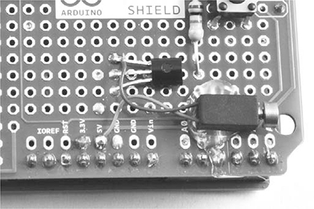
Figure 11-9: Attaching the vibration motor
STEP 5: REPEAT FOR THE OTHER HANDSET
Having built one handset, do the whole lot again for its partner.
STEP 6: PLACING IT INTO AN ENCLOSURE
You may want to scavenge for some small plastic boxes to contain the handsets. Alternatively, you might prefer to go postapocalypse chic and just tape the battery to the Arduino and protoshield, leaving the battery clip accessible as a rudimentary switch.
SOFTWARE
All the source code for this book is available from http://www.nostarch.com/zombies/. See Appendix C for instructions on installing the Arduino sketch for this project, which is called Project_20_Haptic_Communicator.
This project uses a community-maintained Arduino library called Mirf. This library provides an easy-to-use wrapper around the Serial Peripheral Interface (SPI) serial interface to the NRF24 radio module, allowing the Arduino to communicate with the module. The Mirf library must be downloaded from the Internet, which is another good reason to make this project before the outbreak spreads too far. Download the ZIP file for the library from http://playground.arduino.cc/InterfacingWithHardware/Nrf24L01.
Extract the ZIP file and copy the whole Mirf folder into My DocumentsArduinoLibraries if you’re using Windows or Documents/Arduino/libraries if you’re using a Mac or Linux. Note that if the libraries folder doesn’t exist within the Arduino directory, you’ll need to create it before copying.
The Arduino IDE won’t recognize the new library until you restart it, so after copying the library folder, save anything you’re working on, quit the IDE, and restart. Next, open the sketch file for this project and upload it to both Arduinos, one after the other. The sketch starts by importing three libraries:
#include <SPI.h>
#include <Mirf.h>
#include <MirfHardwareSpiDriver.h>
The SPI library is part of the Arduino IDE distribution and simplifies communication with devices using SPI. The MirfHardwareSpiDriver library is also used in the sketch.
Next, three constants are defined:
const int numberOfSends = 3;
const int buzzerPin = 5;
const int switchPin = 2;
The range of wireless communication can be extended by sending the “button pressed” message several times, so that at the edge of the range, only one of the messages has to get through. The constant numberOfSends defines how many times each message should be sent. This is followed by pin definitions for the buzzer and switch pins.
The next constant (buzzerVolume) specifies the analogWrite value for the vibration motor:
const int buzzerVolume = 100; // Keep less than 153 for 3V!
const int buzzMinDuration = 20;
If you are using a 3V motor, it is important that the analogWrite value does not exceed 153; a value of 153 will deliver power equivalent to a 3V supply to the motor, and more power would overload it. Reducing this value will make your buzzer quieter. The buzzMinDuration constant specifies the minimum duration for a buzz in milliseconds. This is important because too short a buzz may not be noticed.
The global byte data array contains a 4-byte message to be sent whenever the button is pressed:
byte data[] = {0x54, 0x12, 0x01, 0x00};
The first three values in this array are chosen as being unique for the pair of haptic communicators. When a message is received, they are checked to see whether they match. This ensures that the communicator has received a real message and not just noise. It also means that you could set up a second pair of devices using different values, and the new pair would not interfere with this pair. Depending on the group dynamics in your band of survivors, you might want to communicate with one person in some situations (“Come save me!”) and another person in other situations (“If you show up now, I bet the zombie will eat your brains and not mine”).
The fourth byte is not used in this project, but it’s there in case you would like the button-press messages to send a parameter. You could, for example, add a second button to the communicator for emergencies that sends a different value in this byte, which could then be read at the receiving end.
Next is the setup function:
void setup()
{
analogWrite(buzzerPin, 0);
pinMode(switchPin, INPUT_PULLUP);
Mirf.spi = &MirfHardwareSpi;
Mirf.init();
listenMode();
Mirf.payload = 4;
Mirf.config();
}
This function starts by making sure the buzzer is off at analogWrite. Then it sets the mode of the switchPin to an input with the internal pull-up resistor enabled (see “Stabilizing Digital Inputs with Pull-up Resistors” on page 252 for more information on pull-up resistors). The radio module is then initialized and put into listen mode, waiting to receive a message.
Next comes the loop function:
void loop()
{
if (!Mirf.isSending() && Mirf.dataReady())
{
Mirf.getData(data);
checkForBuzz();
}
if (digitalRead(switchPin) == LOW)
{
sendBuzz();
}
}
This starts with an if statement that first checks whether the module is itself sending a message. It then checks whether there is data ready to be read, and it reads the message over the radio. Once the message is read, the function checkForBuzz is called to check that the message is legitimate before buzzing the vibration motor.
The loop function finally checks for a button press on this end and responds to a button press by calling the sendBuzz function.
Now, let’s look at the other functions defined in this sketch, starting with listenMode and sendMode:
void listenMode()
{
Mirf.setRADDR((byte *)"serv1");
}
void sendMode()
{
Mirf.setRADDR((byte *)"clie1");
}
The listenMode function puts the radio module into listening mode by setting its receive address to "serv1". The sendMode function puts the radio module into sending mode by setting its receive address to "clie1". We call both the listenMode function and the sendMode function inside sendBuzz, which gets called in the loop function’s last if statement.
Finally, we have the checkForBuzz function:
void checkForBuzz()
{
if (data[0]==0x54 && data[1]==0x12 && data[2]==0x01)
{
analogWrite(buzzerPin, buzzerVolume);
delay(buzzMinDuration);
analogWrite(buzzerPin, 0);
}
}
This function checks the first 3 bytes of the message sent from the other module, and if they match, it turns on the vibration motor for the duration specified in milliseconds by buzzMinDuration.
USING THE HAPTIC COMMUNICATOR
This project is a lot of fun to use. I’m pretty sure casinos are wise to this kind of contraption, though, so to avoid trouble, don’t use it to cheat at the gaming tables. Money will have little use after the apocalypse in any case.
If you’re prepared to learn Morse code, the handsets can be used with Morse, although they are a little slow. Alternatively, you could come up with a simplified vocabulary along the following lines:
• One short buzz: All is well
• One long buzz: Zombies sighted
• Three long buzzes: Zombies close
• Three short buzzes: Run!!
This is the final project in the book, and I hope you have had fun as you’ve equipped yourself for the apocalypse. Whether you’re building these projects in anticipation of the coming zombie hordes or you’re already in hiding, I also hope they help you to survive!