
2
GENERATING ELECTRICITY

In the aftermath of a zombie apocalypse, the national power grid is likely to continue working for only a day or two at most. The system of power generation and distribution is finely balanced and fantastically complex, and the people who run it are likely to be busy either being eaten by zombies or being zombies (Figure 2-1), so you won’t be able to rely on them.
Let’s face it, though: you’re not going to need to have a whole lot to power, anyway. There won’t be any TV to watch, and you won’t have the Internet, either. You’ll only need a fairly small amount of electricity, and fortunately, you can generate that much yourself, either by using the sun’s energy or by converting movement into electricity.

Figure 2-1: Zombie workers
POWER AND ENERGY
The words energy and power are often used interchangeably, but they’re actually different. Power is the amount of energy used per unit time, usually per second. Energy is measured in units called joules (after James Joule, the English scientist and brewer). You could represent power in units of joules per second, but power is more commonly measured in watts (named for James Watt, the Scottish inventor). One watt is actually exactly one joule per second.
Think of a battery as holding a certain number of joules of energy. How fast the battery empties depends on how much power you draw from it. If you attach a very low-power device, the battery will take a long time to go dead, but if you attach something high power, the battery won’t last long at all.
Table 2-1 lists some electrical appliances and indicates just how much power they use.
Table 2-1: POWER CONSUMPTION OF EVERYDAY ITEMS
APPLIANCE |
POWER (W) |
WOULD DRAIN A CAR BATTERY IN: |
|---|---|---|
Portable FM radio |
2 |
300 hours |
LED light bulb |
5 |
120 hours |
Soldering iron |
30 |
20 hours |
Laptop |
50 |
12 hours |
Monitor (27 inch) |
80 |
7.5 hours |
Hair dryer |
1,500 |
24 minutes |
Electric room heater |
3,000 |
12 minutes |
Electric shower (the type that both pumps and heats the water) |
10,000 |
3.6 minutes |
Cooking and heating require a lot of power. In fact, if you want hot water or hot food, you should look at burning fuel rather than using electricity.
FLAVORS OF ELECTRICITY
Although Table 2-1 lists a portable radio and an electric shower, these things need different types of electricity. Fortunately, that doesn’t have to be a problem! With some constraints, it is possible to convert between these types. Note that zombies will be unable to manage this task (Figure 2-2).
Devices that use electricity fall into two categories: those that require high-voltage alternating current (AC) and those that require low-voltage direct current (DC). DC devices are often battery powered.

Figure 2-2: Flavors of electricity
LOW-VOLTAGE DC
Low-voltage DC is much safer and easier to generate, use, and store than AC. Low-voltage generally means 12V (volts) or less. I find it helps to think of water flowing through pipes when trying to understand how electricity flows through wires. This image is particularly useful for understanding the difference between voltage and current.
Voltage is like the pressure in a water pipe. A high voltage can supply much more power than a lower voltage can, just as a high-pressure pipe could fill a container with water much faster than a lower-pressure pipe could. But thinking of voltage as just pressure creates an incomplete picture; it’s more accurate to think of voltage as a height difference.
In the schematic (Figure 2-3), the point where the water enters the pipe is above the point where the water leaves the pipe. The higher the entrance is above the exit, the greater the rate of flow. This rate of flow is called the current, and in electronics, the current is the amount of charge passing a point per second. The unit of measurement for current is the ampere, which is abbreviated to just A. It is also common to see current measured in mA (milliamps). One mA is 1/1,000 of an A.

Figure 2-3: Voltage and current
Interestingly, you can work out the amount of power that something uses by multiplying the power in voltage (V) by the current in amperes (A).
When supplying some low-voltage equipment (let’s say an FM radio receiver) with power, it’s important to get the voltage correct. Too much voltage will cause too much current to flow through the radio and may kill it. The last thing you need is a zombie radio! Similarly, if there’s too little voltage, not enough current will flow to make the thing work properly. The range of acceptable voltage can be quite wide, depending on the device. For example, a radio indicated as requiring 6V to operate may work perfectly well at anything between 4V and 8V.
WARNING
When using a low-voltage DC device, make sure you put the batteries in the right way around. Batteries have a positive and a negative connection. If you connect them incorrectly, the current will try to flow the wrong way through the device. If the device does not have internal protection against this (note that most do), the device may be rendered nonfunctional.
HIGH-VOLTAGE AC
High voltage is used to distribute electricity to people’s homes because higher voltage makes power transmission more efficient. High-voltage AC is very different from low-voltage DC. For one thing, the voltage is either 120V (in the United States) or 220V (in most of the rest of the world). Also, AC voltage is alternating: unlike a battery, which has one positive connection and one negative, an alternating current switches the polarity of its two leads between positive and negative at a rate of 60 times a second (in the United States) or 50 times per second (in most of the rest of the world). The unit for frequency, which is the number of times that the electricity switches polarity per second, is hertz (Hz).
How the voltage changes over time with an AC power source can be graphed, as in Figure 2-4. Notice that the voltage doesn’t suddenly switch direction but rather swings gently one way and then the other, gradually increasing to a peak of over 150V and then down to below –150V. Clearly, this is more than 120V on either side of zero. The maximum and minimum are described as 120V because this amount of AC power provides the equivalent amount of power as 120V DC. This way of measuring AC voltage is called root mean square (RMS). For more information on this topic, take a look at http://www.electronics-tutorials.ws/accircuits/rms-voltage.html.

Figure 2-4: Alternating current (AC)
Low-voltage DC devices are often run on AC by using an adapter, like the one your laptop uses or the “wall wart” that you plug your phone into, which converts the AC into DC and drops the voltage at the same time. In our postapocalypse world, unless you have an AC generator, you’re likely to be both making and using low-voltage DC directly. Although you can convert DC to AC with a device called an inverter, converting in either direction is inefficient, wasting some energy, and is best avoided.
If you decide to use an inverter, remember that even though you are powering it from a battery, it is generating high and therefore dangerous voltages. Therefore, exercise the same common sense as you do when plugging devices into an AC wall outlet.
BATTERIES
Batteries, used to store electrical energy, come in lots of different types. Some are small and single-use, like AA cells. Others, such as lithium laptop batteries and lead-acid car batteries, can be recharged. Note that batteries only supply DC.
Both single-use and rechargeable batteries are essential to your survival during a zombie apocalypse, so scavenge as many as you can during your supply runs. As you’ll see in Chapters 9, 10, and 11 of this book, you can use batteries to power zombie-distracting devices and communications devices. Of course, both types of batteries have different merits. Let’s explore those now so you can decide which deserves a spot in your go bag.
SINGLE-USE BATTERIES
AA batteries have a long shelf life, and to operate many small appliances, it makes sense to scavenge a good supply of these. They also run out of power slowly. For example, if your flashlight begins to dim, you’ll still get a few valuable minutes of light before the battery completely dies. Note that rechargeable AA batteries usually give out much more quickly than single-use batteries—and with less warning.
RECHARGEABLE BATTERIES
Lithium polymer (LiPo) batteries have transformed mobile devices because they’re lightweight and can store a lot of energy. Since a cellphone is so easy to carry around, you might think LiPo batteries are a good rechargeable choice for any portable postapocalyptic device. But be warned: they have a few quirks:
• They are prone to catching fire if overcharged, punctured, or cut.
• They require special charging circuits.
• They don’t work well at extremes of temperature.
In short, for storing energy that you generate, it’s better to use the lead-acid batteries that you find in cars. For a start, there should be a plentiful supply of these. They also have the advantage of working at low temperatures, and they are much more forgiving of overcharging or continuing to be discharged after they are empty than other types of rechargeable batteries. The only real downside to lead-acid batteries is that they are really heavy, so when you need to scavenge car batteries, don’t be tempted to load your pack with much else. Otherwise, you’ll quickly find yourself too overburdened to escape a pursuing zombie.
BATTERY CHARGING
Under normal circumstances, the easiest way to charge a battery is to use an AC-powered battery charger. Since you won’t have access to AC (unless you’ve hit the jackpot and found a working generator), you need to consider ways you can generate electricity to charge batteries.
In the project that follows, you’ll learn how to generate electricity and charge batteries using solar power, in many ways the easiest solution to postapocalyptic power problems. You’ll then discover how a stationary bicycle and a car alternator can be adapted to charge batteries. The principles you learn here also govern using water wheels and wind turbines. In fact, anything that can turn the shaft of a car alternator at a reasonable speed and with reasonable force can be used to generate power. A drive belt is a good way to link whatever is turning to the alternator and provide some gearing so that the alternator moves fast enough.
PROJECT 1: SOLAR RECHARGING
This project will show you how to make a simple setup that charges a 12V car battery using solar power.
SOLAR PANELS
Photovoltaic (PV) solar panels are silent, require minimal maintenance, and will just sit there happily generating electricity. They generate a lot more electricity when the sun is out, but they still make useable amounts of electricity on an overcast day. Obviously, they’re useless at night, which is why you’ll use them to charge batteries, not power a device directly. They also need to be situated with a clear view of the sky and out of zombie climbing height, as an undead entity partially obscuring a solar panel will drastically reduce its efficiency.
You may find solar panels to scavenge on the roofs of houses or even in arrays on the ground. Your electricity needs are likely to be relatively modest, so one or two panels will be plenty. After all, we’re talking about survival here; the hot tub can wait.
As you might expect, the generating capability of solar panels is measured in watts. But make no mistake: a solar panel labeled “100W” may generate just about 100W at noon on a cloudless day on the equator, but most of the time, it will generate a lot less than that.
Solar panels incorporate different types of technology, the most common types being monocrystalline silicon and polycrystalline silicon. The mono panels are more efficient and produce more power per square foot, but the poly panels still make perfectly good electricity. They just need to be a little larger to make as much. It does not matter what type you take; all you really need to be aware of is the number of watts. If you turn the solar panel over, you should find a label that gives you all the key data about the panel.
CHARGE CONTROLLERS
Domestic solar installations don’t charge batteries. Instead, a complex piece of equipment converts the low-voltage DC produced by the solar panels into high-voltage AC. The converted power is first used to meet the demands of the house’s AC wall sockets and lighting. Then anything left over goes into the power company’s AC lines, and the power company pays for the contribution of excess electricity. Well, that’s what happens if you’re reading this before the apocalypse. Otherwise, it’s likely everyone at the power company has become a zombie, and money has become meaningless.
Instead of giving your excess electricity away to a power company that doesn’t care and won’t pay for it, store it in batteries for later use. This project works just like the way you’d manage electricity for a motor home or boat that uses PV cells to charge its batteries when the vehicle is not in use.
Rather than build an electronic circuit to control the charging, it’s much easier and more reliable to use a ready-made charge controller. If you’re buying preapocalypse, then pick one up on eBay, at another online retailer, or at a physical store, like Fry’s. If you’re buying postapocalypse, then they’re available free of charge from physical stores.
WHAT YOU WILL NEED
To make this project, you’ll need the following items.
ITEM |
NOTES |
SOURCE |
|---|---|---|
|
7A (or more) 12V |
eBay, Fry’s (4980091), abandoned RVs and boats |
|
20W-100W |
eBay, Scavenge |
|
12V |
Auto parts store, Scavenge |
|
7A or more |
Auto parts store |
|
7A |
Scavenge |
|
10A |
Home Depot, Lowe’s, Menards |
|
Simple multimeter |
Auto parts store, eBay, Fry’s |
Solar panel specifications have become pretty standardized. Look for a solar panel that generates between 20W and 100W and is labeled as 12V. That means the panel is suitable for charging 12V batteries. Nominally, 12V solar panels will actually produce upwards of 18V.
The power cable needs to be long enough to connect the solar panel to the charge controller. This cable could be an AC outlet extension with the connectors cut off each end. Thin, low-current cable has a higher resistance to the flow of current than higher-current cable, which will waste precious power. For example, a 10A AC outlet extension cable that’s 30 feet (10 m) long will waste about 0.5W of power for a 20W solar panel charging at about 12W. For this reason, use a thick cable and keep its length short if you can.
Since you will be making your multimeter a permanent part of this project and you will also be chopping up the test leads, I urge you to use the cheapest possible multimeter. You will probably also find it useful to have another multimeter to use for testing.
In addition to the components listed above, you will need the following general construction tools:
• Drill
• Screws (assorted sizes)
• Screwdriver
You’re going to use multimeters a lot in this chapter, too. Take a look at “Using a Multimeter” on page 237 to find out more about how to use this useful little tool.
CONSTRUCTION
The most difficult part of this project is likely to be fixing the solar panel somewhere reliable, where the zombies and wind cannot displace it. A roof is probably a good idea, but it’s up to you to figure out the best place for the panel in your compound. Remember, you’re going to need to run a cable from the solar panel to the area where you plan to keep the battery and charge controller.
The diagram shows the wiring for the project (Figure 2-5).

Figure 2-5: Solar panel wiring diagram
Charge controllers are all a little different from each other, but most will have six terminals, each in pairs of + and–. One pair will connect to the solar panel, another will connect to the battery, and the third pair (not shown in Figure 2-5) will connect to whatever you want to power with the battery. For now, let’s just worry about charging the battery; I’ll show you how to use that stored energy later.
The charge controller will monitor the battery voltage and the voltage coming from the solar panel to ensure that the battery doesn’t overcharge or deplete so far that it stops accepting charge. More advanced models may have a display to show you what’s going on, but I used a very basic model, so I also used a multimeter to show how much current is flowing into the battery. If your charging controller does this for you, then you can probably do without the multimeter. In that case, the charge controller’s positive connection goes straight to the positive battery connection, without the meter in between.
STEP 1: FIX THE SOLAR PANEL
It should go without saying that the solar panel should go somewhere sunny and far out of a zombie’s reach, but near a window inside your base won’t be good enough. Ideally, it needs to be on a south-facing roof. The angle depends on your latitude. For optimal performance, the further from the equator you are, the closer to the vertical the panel should be tilted. If your base has a slanted roof, you can probably just attach the panel to the natural slope of the roof, as roofs tend to have steeper angles further from the equator to allow snow and rain to run off more easily.
You may have to improvise with wooden batons to attach the panels. The photograph shows my solar panel mounted on a roof (Figure 2-6).

Figure 2-6: Solar panel ready to make power
STEP 2: ATTACH A LEAD TO THE SOLAR PANEL
The solar panel may have screw terminals, or, as mine does, it may have a short length of wire soldered to its terminals. The lead attached to the solar panel needs to be long enough to reach inside your base, where you can ensure it stays dry. Attach a lead that can be fed through a hole on the wall or in the roof and attached to the screw terminals. Just like zombies, water is likely to find its way through any gap, so seal up holes after you have threaded the cable through. Silicone sealant works well for this.
Once the cable is inside, you can use the terminal block to extend it to the length you need, though a single length of cable without joins will be most reliable. A terminal block can be used to join the lead from the solar panel to a longer lead, which will be connected to the charge controller (Figure 2-7).

Figure 2-7: Connecting the solar panel
STEP 3: WIRE UP THE BATTERY AND CHARGE CONTROLLER
Wire up the battery, multimeter, and charge controller as shown in Figure 2-5. The red probe lead from the multimeter can fit in the screw terminal of the charge controller, but the black probe needs to connect to the battery somehow. The best way is to attach one end of the black probe to one of the heavy-duty alligator clips.
This means we need to make three leads, using the alligator clips and probe leads. For the first of these leads (labeled ➊ in Figure 2-5 and shown in Figure 2-8, I just used half of the multimeter’s black lead, with the probe cut off. However, you can use any black wire you like.

Figure 2-8: Negative battery lead
This lead will connect the battery to the negative (–) terminal of the charge controller. To make the lead, strip about half an inch (10 mm) of the insulation from each end of the wire. Connect one of those ends to the alligator clip by wrapping the wire clockwise around the loosened bolt on the clip. Then tighten the bolt so the clip grips the bare wire.
NOTE
The wire should be wrapped clockwise around the bolt so that when you turn the bolt, it pulls the wire around with it rather than pushes it away. The connection just works better that way.
Use a pair of pliers to wrap the supporting tabs at the end of the clip around the wire. These will prevent the wire from pulling off the clip if the wire is accidentally pulled on.
The second of the three leads (labeled ➋ in Figure 2-5 and shown in Figure 2-9) will go from the positive high-current terminal of the multimeter to the positive battery output of the charge controller. This lead is just the positive meter lead with the probe cut off and the insulation stripped off the last half inch (10 mm).

Figure 2-9: Positive charging lead
You’ll connect the final of the three leads (labeled ➌ in Figure 2-5 and shown in Figure 2-10) from the negative (COM) connection of the multimeter to the alligator clip that will be connected to the positive terminal of the battery.
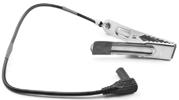
Figure 2-10: Positive battery lead
Strip about half an inch (10 mm) of insulation from the remainder of the black probe lead of the multimeter and attach it to the alligator clip in the same way you did for the lead ➋. This new lead is going to be connected to the positive terminal of the battery.
This lead is black, however, and since the convention is that black means negative, the color could be confusing. To make the purpose of this lead more intuitive, wrap some red electrical tape around it to make red stripes and add some red tape to the “finger end” of the alligator clip.
Now use the three leads to connect everything together, ready for use (Figure 2-11). Note that most multimeters have a special positive socket just for high currents. This may be labeled 10A or 5A. Plug the red lead into that socket. Be sure to set meter to the correct range, which is DC current at the meter’s maximum available current reading.
STEP 4: TESTING
To test the solar panel, use the highest DC amps setting of the multimeter to monitor how much current flows into the battery from the panel via the charge controller. If the battery needs charging, the charge controller should attempt to charge the battery as much as possible until it is full, and the meter should show a positive reading. After the battery is full, most charge controllers will switch to a trickle-charge mode that just keeps the battery topped up.

Figure 2-11: The charge controller, multimeter, and battery are connected.
In Figure 2-11, 0.84A of current is flowing into the battery. If your current reading is negative, then current is flowing out of the battery. This means something is wrong, so check over your wiring. You should also see the current drop considerably if you cover part of the solar panel or if the sun goes away.
If the battery doesn’t need charging, then the meter should read zero, which doesn’t tell you much. You’ll have to wait until Chapter 3, when we attach some lighting to the battery, to see the charging process in action.
USING THE SOLAR CHARGER
To ensure a continuous supply of electricity, it’s a good idea to duplicate this entire design so that if one solar panel or set of wiring should fail, you have a spare. Since swapping batteries just means unclipping the alligator clips, you can even keep a stack of batteries in rotation and set a few fully charged batteries aside for emergencies. Stockpile batteries for your own base, or start a new career as a postapocalyptic battery shop owner. Money might be useless, but I’m sure you could barter electricity for food, supplies, or assistance with your next scavenging trip.
On a sunny day, if lots of current is flowing from the solar panels, you may find that the alligator clips get hot. Wrapping some tape around them will reduce the chance that you’ll burn your fingers when you swap in a new battery.
PROJECT 2: BICYCLE GENERATOR
In this project, you’ll generate power with an adapted bicycle, which doubles as a great way to stay in shape so you can outrun the undead. The design uses a car alternator to charge the car battery. The alternator is just doing what it would naturally in a car, but without an engine. The alternator includes all that is needed to charge the car battery, so in this project, there is no need for the charge controller that you used in the solar project.
NOTE
You could also adapt this project to use other forms of rotary movement. For example, you could connect it to a wind turbine, a water wheel, or zombies on a treadmill (Figure 2-12).

Figure 2-12: Zombie power
WHAT YOU WILL NEED
To make this project, you will need the following items.
ITEM |
NOTES |
SOURCE |
|---|---|---|
|
Large wheels |
Scavenge |
|
Almost any will work |
eBay, Scavenge |
|
12V |
Auto parts store, Scavenge |
|
V belt, size A100 |
Auto parts store, eBay, hardware store, scavenge |
|
7A or more |
Auto parts store |
|
To suit your alternator terminals |
Auto parts store |
|
To suit your alternator terminals |
Auto parts store |
|
7A |
Scavenge |
|
Simple multimeter |
Auto parts store, eBay, Fry’s |
|
12V 5W lamp |
Auto parts store |
|
10A fuse and holder |
Auto parts store |
|
|
Hardware store |
|
5 feet (1.5 m) |
Hardware store |
This is another project that uses a multimeter as a fixture, and I would again suggest you use the cheapest possible multimeter. You will probably also find it useful to have a spare multimeter to use for testing.
CONSTRUCTION
The trick to building this project is to keep the cycle’s back wheel away from the ground. There are two ways to do this. One is to make (or scavenge) a stand designed to allow a regular bike to be used as an exercise bike. This needs to be strong enough to support you when you sit on the bike, so a maintenance stand probably won’t be strong enough.
The other approach is to turn the bike upside down. Then you can use the pedals with either your hands or your feet while you sit in a chair near where the handlebars used to be. I used the upside-down bike approach.
If you know a little about electronics, you may be aware that most DC motors can be used to generate current. Moving a coil of wire in a magnetic field (usually supplied by a regular magnet) will cause a current to be generated in that wire.
Alternators, like all generators, operate on this basic principle, but instead of a normal magnet, the magnetic field that the generating coil turns in is created by an electromagnet. The electromagnet is powered by the alternator itself once it gets going. To get going, the alternator must be connected to the battery; other-wise, there will no magnetic field for the generation to start. It’s a chicken-and-egg situation: the alternator needs to be generating current in order to generate current.
Figure 2-13 shows a simplified schematic of a car alternator.

Figure 2-13: The schematic diagram for an automotive alternator
In actual fact, the alternator will normally have three stator coils producing three-phase AC to be turned into DC (unlike ordinary domestic two-phase AC). If you want to find chapter and verse on alternators, then take a look at the description at http://www.allaboutcircuits.com/vol_6/chpt_4/8.html.
STEP 1: MODIFY THE BICYCLE
First, strip off every piece of the bike that you don’t need. You can take away the front wheel, both mudguards, and the brakes. The gears can stay.
Remove the rear wheel and remove its tire and inner tube. Then place the drive belt over the wheel and fix the wheel back onto the bike.
STEP 2: FIX THE ALTERNATOR AND BIKE TO THE 2×4
Alternators don’t have standard positions for their fixing lugs, so you may have to improvise a little here. The drive wheel of the alternator needs to line up with the cycle’s wheel, but the alignment doesn’t need to be exact, especially if you use a long belt like the one in my final arrangement (Figure 2-14).

Figure 2-14: The mechanical arrangement of bike and alternator
Use a G-clamp to fix the bike to the 2×4 using the saddle. Adjust the saddle first so that it is flat. Alternatively, you could also remove the saddle completely and make a hole of the same diameter as the saddle stem partway through the 2×4.
Where you place the alternator on the 2×4 depends on the geometry of the alternator, the bike, and the drive belt, so I can’t give you exact measurements. Fix the alternator in place once the bike is attached to the 2×4 and the drive belt is around the cycle wheel. The alternator I used had a convenient hole that allowed it to be fixed to the side of the 2×4 (Figure 2-15). The drive belt doesn’t need to be under a lot of tension, but you can create a simple tensioner with a spring or elastic strap; you can even cut the latter from the discarded bike inner tube.

Figure 2-15: Attaching the alternator to the 2×4
Turn the cycle very gently to make sure everything is working mechanically and then move on to the next step.
WARNING
Don’t be tempted to try whizzing the alternator around at high speed without attaching the rest of the circuit, because generating high voltage in the coils with no load can damage the built-in electronics of the alternator.
STEP 3: IDENTIFY THE ALTERNATOR TERMINALS
Now that the mechanical part of the generator is built, we can start looking at the electrical side. First identify the connections on the alternator. Although they have slight differences, automotive alternators are remarkably standard, especially those from older cars. Plus, alternators are often easy to remove from older vehicles.
I used a reconditioned alternator that I bought on eBay for just a few dollars (Figure 2-16). Postapocalypse, however, there should be no shortage of abandoned old cars.

Figure 2-16: Delco LRA443 alternator (from the 1980s)
You are looking to identify three connections from the alternator:
Negative charging terminal (–) This will normally be connected electrically to the metal case of the alternator, but there should also be a bolt specifically for attaching a spade terminal. It may be marked –, GROUND, or GND.
Positive charging terminal (+) Although it may not look like it, this will be electrically isolated from the metal body of the alternator. This terminal is usually marked with a +, but it may be marked BATT or BATT +. It’s quite common for alternators to have two + terminals that are connected together inside the alternator. If this is the case, you can use either terminal.
Field connection (D+) On my alternator, this is labeled D+, although it is just as common for it to be labeled F.
STEP 4: WIRING
Now that you know which terminal of the alternator is which, you need to make some leads to connect everything together. The wiring diagram shows how to do this (Figure 2-17).

Figure 2-17: Wiring diagram for the cycle charger
The light bulb serves two purposes. It limits the current to the field coil so you don’t have to pedal too hard to kick-start the alternator into generating. The bulb also serves as a useful indicator: when the alternator starts generating, the light will go out.
There are a few leads to make. Let’s start with the lead from the negative terminal of the alternator to the battery negative terminal (➊ in Figure 2-17). This needs a large alligator clip on the battery end and a butt connector on the other, as shown (Figure 2-18).

Figure 2-18: The negative battery lead
You could use any black wire for this lead, but I used two-thirds of a black multimeter lead, from the probe end of the multimeter, and cut off the probe itself. Strip about half an inch (10 mm) of the insulation off each end of the wire. The butt terminal can be crimped (squeezed with pliers) onto the lead. Attach the alligator lead by wrapping the stripped wire clockwise around the bolt before tightening up the bolt.
This charging circuit doesn’t include a charge controller to protect it, so you’ll need a fuse. Fuses are short lengths of metal designed to melt and so break a connection when too much current flows through them. A car battery can store quite a lot of energy—enough to start a fire—so it’s worth using a fuse. If something should accidentally short out, the fuse will blow, breaking the connection before too much damage is done.
The most convenient type of fuse holder has trailing wires at each end. You can use these trailing wires to make the lead between the positive terminal of the battery and the multimeter (➋ in Figure 2-17). Attach an alligator clip lead to one fuse wire and attach the remaining third of the black multimeter lead to the other fuse wire. Wrap the connection between the fuse and multimeter leads with electrical tape, and you should have the completed lead (Figure 2-19).

Figure 2-19: The fuse lead
The final of the three leads (Figure 2-20 and ➌ in Figure 2-17) combines both the lamp and the positive charging connector from the alternator to the multimeter.

Figure 2-20: The positive charging and light bulb lead
As with the fuse holder, I used a light bulb holder with trailing leads. Crimp a ring terminal of the correct size for the F connection of the alternator. It’s best to use an insulated spade terminal to minimize the chances of a short circuit.
Chop off the probe from the red multimeter lead, strip half an inch (10 mm) of insulation off the lead, and twist the bare wires together with the other lead of the light bulb holder. Crimp the combined wires together into the butt terminal for the positive charging connection of the alternator.
STEP 5: FINAL ASSEMBLY
With all the leads prepared, it’s time to connect everything according to the diagram in Figure 2-17.
The photograph shows the alternator, battery, and multimeter all wired up (Figure 2-21). Before you connect the battery and alligator clip, make sure the multimeter is set to its maximum current range and that the correct sockets for maximum DC current are being used.

Figure 2-21: The completed wiring
USING THE PEDAL GENERATOR
Before you start pedaling, the bulb should be on, and the multimeter should indicate a current of about –0.3A. The value is negative because this current is being used by the lamp.
Crank the pedals quite fast, and you should see the lamp start to dim and then extinguish. At this point, you’ll probably feel a lot more resistance from the pedals. This is good news: you’re generating electricity! The current should now show a positive value. With furious pedaling, this might increase to 2A or 3A.
If your battery is fully charged, then the bulb should go out while the current remains at zero. This is because the alternator includes a voltage regulator circuit that stops charging the battery when it’s up to its maximum voltage. If you need to discharge the battery a little to test that it charges, then you might want to move on to the next project—where we start using some of the energy that we’ve stored in the battery—and return to test this project later.
You should only connect the charging circuit when you are ready to start using it, as the light bulb will eventually drain the battery completely.
Once you’ve successfully built one pedal-powered generator, you can repeat these instructions to build a charging station for each person in your base. By generating electricity as a team, you’ll stockpile plenty of batteries, and everyone will be able to contribute to your group’s continued survival!
We’ve thoroughly explored a few ways of generating electricity and, in particular, charging up car batteries. In the next chapter, you will learn how to start using this electricity and monitor the state of your batteries so that you don’t suddenly get plunged into darkness.