PROGRAMMING makes up a relatively small amount of the effort in a mass market game. Most of the development time goes into content creation, making models, textures, environments, sounds, music, and animation—everything from the concept art to the fine tuning of the level.
Over the last 15 years developers have reduced the programming effort further by reusing technology on multiple titles, creating or licensing a game engine on which several games can run. Adding a comprehensive suite of AI to the engine is a natural extension.
Most developers aren’t content to stop there, however. Because the effort involved in content creation is so great, the content creation process also needs to be standardized, and the runtime tools need to be seamlessly integrated with development tools. For more than a decade these complete toolchains have been essential for development of large games. With the explosion in popularity of the Unity engine, they have become crucial to the existence of small studios, independent developers, and hobbyists.
In fact, it is difficult to overstate the importance of the toolchain in modern game development. At the time of the first edition of this book, the toolchain was seen as a major deciding factor in a publisher’s decisions to back a project. Now it is almost ubiquitous. It is a rare and brave developer indeed that creates a new game from scratch without a proven toolchain in place.
Partly this is due to their availability. Renderware Studio was a major selling point for Criterion’s graphics middleware in the early 2000s. But licensing it was costly and required a detailed agreement with a vendor. Now it is trivial to download Unity or Unreal Engine from the web, experiment under a simple end user license, and have access to a widely supported and powerful toolchain. These tools are not free, but their ease of use has transformed the industry. In addition to these two market leaders, other systems such as the open source Godot and Amazon’s Lumberyard (a fork of the Crytek’s Cryengine) also emphasize the same style of game development, with the toolchain and a custom editor application at the core.
The importance of toolchains places limits on the AI. Advanced techniques such as neural networks, genetic algorithms, and goal-oriented action planning (GOAP) haven’t been widely used in commercial titles. To some degree this is because they are naturally difficult to map into a level editing tool. They require specific programming for a character, which limits the speed at which new levels can be created and the code reuse between projects.
The majority of AI-specific design tools are concerned with the bread-and-butter techniques: finite state machines or behavior trees, movement, and pathfinding. These approaches rely on simple processes and significant knowledge. Toolchains are naturally better at allowing designers to modify data rather than code, so use of these classic techniques is being reinforced.
12.0.2 WHERE AI KNOWLEDGE COMES FROM
Good AI requires a lot of knowledge. As we’ve seen many times in this book, having good and appropriate knowledge about the game environment saves a huge amount of processing time. And at runtime, when the game has many things to keep track of, processing time is a crucial resource.
The knowledge required by AI algorithms depends on the environment of the game. A character moving around, for example, needs some knowledge of where and how it is possible to move. This can be provided by the programmers, giving the AI the data it needs directly.
When the game level changes, however, the programmer needs to provide new sets of data. This does not promote reuse between multiple games and makes it difficult for simple changes to be made to levels. A toolchain approach to developing a game puts the onus on the content creation team to provide the necessary AI knowledge. This process can be aided by offline processing which automatically produces a database of knowledge from the raw level information.
For years it has been common for the content creation team to provide the AI knowledge for movement and pathfinding. Either explicitly, by marking up the level itself, or by having such data generated automatically from the content they create. More recently, decision making and higher level AI functions have also been incorporated into the toolchain, usually via custom tools integrated into the editor application.
12.1 KNOWLEDGE FOR PATHFINDING AND WAYPOINTS
Pathfinding algorithms work on a directed graph: a summary of the game level in a form that is optimal for the pathfinding algorithm. Chapter 4 discussed a number of ways in which the geometry of an indoor or outdoor environment could be broken into regions for use in pathfinding. The same kind of data structure is used for some tactical AI. Fortunately, the same kinds of tool requirements for pathfinding apply for waypoint tactics.
Breaking down the level geometry into nodes and connections can be done manually by the level designer, or it can be done automatically in an offline process. Because manually creating a pathfinding graph can be a time-consuming process (and one that needs to be redone each time the level geometry changes), many developers use automatic processes, at least for an initial draft. Results of purely automatic processes are typically mixed, with more issues showing as the level becomes more complex. Some human supervision is usually required for optimum results.
12.1.1 MANUALLY CREATING REGION DATA
There are three elements of a pathfinding graph that need to be created: the placement of the graph nodes (and any associated localization information), the connections between those nodes, and the costs associated with the connections.
The entire graph can be created in one go, but it is common for each element to be created separately using different techniques. The level designer may place nodes in the game level manually. The connections can then be calculated based on line-of-sight information, and the costs can be calculated likewise algorithmically.
To some extent, the cost and connections between nodes are easy to calculate algorithmically. Placing nodes correctly involves understanding the structure of the level and having an appreciation for the patterns of movement that are likely to occur. This appreciation is much easier for a human operator than an algorithm.
This section looks at the issues involved with manually specifying graphs (mostly the nodes of a graph). The following section examines automatic calculation of graphs, including connections and costs.
To support the manual creation of graph nodes, the facilities of the level editing tool depend on the world representation used.
Tile Graphs
Tile graphs do not normally require designers to manually specify any data in the modeling tool. The layout of a level is normally fixed (an RTS game, for example, typically is always based on a fixed grid, often of a limited number of different sizes).
The cost functions involved in pathfinding also need to be specified. Most cost functions are based on distance and gradient, modified by parameters particular to a given type of character. These values can usually be generated automatically (gradients can be calculated directly from the height values, for example). Character-specific modifiers are usually provided in the character data. An artillery unit, for example, might suffer ten times the gradient cost of a light reconnaissance unit.
Often, the level design tool for a tile-based game can include the AI data behind the scenes. Placing a patch of forest, for example, can automatically increase the movement cost through that tile. The level designer doesn’t need to make the change in cost explicit or even need to know that AI data are being calculated.
As a result, no extra infrastructure is required to support pathfinding on tile-based graphs. This is one reason why they have continued to be used so extensively in the AI for games that require a lot of pathfinding (such as RTS), even when the graphics have moved away from sprite tiles.
Dirichlet Domains
Dirichlet domains are a useful world representation in a range of genres. They are applicable (in the form of waypoints) to everything from driving games to shooters to strategy games.
The level editor needs only to place a set of points in the game level to specify the nodes of the graph. The region associated with each point is the volume that is closest to that point than to any other.
Most level editing tools, and all three-dimensional (3D) modeling tools, allow the user to add an invisible helper object at a point. This can be suitably tagged and used as a node in the graph.
As discussed in Chapter 4, Dirichlet domains have some problems associated with them. Figure 12.1 shows two Dirichlet domains in two adjacent corridors. The regions associated with each node are shown. Notice that the edge of one corridor is incorrectly grouped with the next corridor. A character that strays into this area will think it is in a completely different area of the level. Therefore, its planned path will be wrong.
Similar problems with region grouping occur vertically, where one route passes over another. The problems are compounded when different “weights” can be associated with each node (so a larger volume is attracted to one node than to another). This is illustrated in Chapter 4.
Solving this kind of misclassification can involve lots of play testing and frustration on the part of the level designer. It is important, therefore, for tools to support visualization of the regions associated with each domain. If level designers are able to see the set of locations associated with each node, they can anticipate and diagnose problems more quickly.
Many problems can be avoided altogether by designing levels where navigable regions are not adjacent. Levels with thin walls, walkways through rooms, and lots of vertical movement are difficult to properly divide into Dirichlet domains. Obviously, changing the feel of a game is not feasible simply for the sake of the AI mark-up tool.

Figure 12.1: Dirichlet domains misclassifying a corridor
Navigation Meshes
The same polygon mesh used for rendering can be used as a navigation mesh for pathfinding. Each floor polygon is a node in the graph, and the connectivity between nodes is given by the connectivity between polygons.
This approach requires the level editor to specify polygons as being part of the “floor.” This is most commonly achieved using materials: a certain set of materials is considered to be floors. Every polygon to which one of these materials is applied is part of the floor. Some 3D tools and level editors allow the user to associate additional data with a polygon. This could also be used to manually flag each floor polygon.
In either case, it can be useful to implement a tool by which the level editor can quickly see which polygons are part of the floor. A common problem is to have a set of decorative textures in the middle of a room, which is wrongly marked as “non-floor” and which makes the room unnavigable. This can be easily seen if the floor polygons can be visualized easily.
Navigation meshes have a reputation for being a reliable way of representing the world for pathfinding. They are supported out of the box by both Unity and Unreal Engine, and so have become the most commonly used technique. They are not without issue, however. As discussed in the pathfinding chapter, some level geometry can lead to sub-optimal graphs. Once again, the ability to have a human override the automatically generated graph is very useful.
Bounded Regions
The most general form of pathfinding graph is one in which the level designer can place arbitrary bounding structures to make up the nodes of the graph. The graph can then be built up without being limited to the problems of Dirichlet domains or the constraints of floor polygons.
Arbitrary bounding regions are complex to support in a level design or modeling tool. This approach is therefore usually simplified to the placement of arbitrarily aligned bounding boxes. The level designer can drag a bounding box over regions of the game level to designate that the contents of that box should count as one node in the planning graph. Nodes can then be linked together and their costs set manually or generated from geometrical properties of the node boxes.
12.1.2 AUTOMATIC GRAPH CREATION
With many of the previous approaches, an algorithm can be used to calculate the costs associated with connections in the graph. Approaches based on manually specified points of visibility or Dirichlet domains also use algorithms to determine the connectivity between nodes.
Automatically placing the nodes in the first place is considerably more difficult. For general indoor levels, there is no single optimum technique. In my experience developers who rely on automatic node placement will eventually need to have a mechanism for allowing the level designer to exert some influence and manually improve the resulting graph.
Automatic node placement techniques can be split into two approaches: geometric analysis and data mining.
Geometric analysis techniques operate directly on the geometry of the game level. They analyze the structure of the game level and calculate the appropriate elements of the pathfinding graph. Geometric analysis is also used in other areas of game development, such as calculating potentially visible geometry, performing global radiosity calculations, and ensuring that global rendering budgets are met.
Calculating Costs
For pathfinding data, most geometric analysis calculates the cost of connections between nodes. This is a relatively simple process, so much so that it is rare to find a game whose graph costs have been set by hand.
Most connection costs are calculated by distance. Pathfinding is usually associated with finding a short path, so distance is the natural metric. The distance between two points can be trivially calculated. For representations where nodes are treated as points, the distance of a connection can be taken as the distance between the two points.
A navigation mesh representation usually has connection costs based on the distance between the centers of adjoining triangles. Bounding region representations can similarly use the center points of regions to calculate distances.
Calculating Connections
Calculating which nodes are connected is also a common application. This is most commonly performed by line-of-sight checks between points.
Point-Based Representations
Point-based node representations (such as Dirichlet domains and point-of-visibility representations) associate each node with a single representative point. A line-of-sight check can be made between each pair of such points. If there is a line of sight between the points, then a connection is made between the nodes.
This approach can lead to vast numbers of connections in the graph. Figure 12.2 shows the dramatic complexity of a visibility-based graph for a relatively simple room.
For this reason, concerns are often raised about the performance of visibility-based graphs. But such concerns are curious, since a simple post-processing step can easily rectify the situation and produce usable graphs:
1. Each connection is considered in turn.
2. The connection starts at one node and finishes at another. If the connection passes through intermediate nodes on the way, then the connection is removed.
3. Only the remaining connections form part of the pathfinding graph.
This algorithm looks for pairs of nodes that are in line of sight but where there is no direct route between them. Because a character will have to pass through other nodes on the way, there is no point in keeping the connection.
The second part of Figure 12.2 shows the effect of applying the algorithm to the original graph.
Arbitrary Bounding Regions
Arbitrary bounding regions are usually connected in a similar way to points. A selection of sample points are chosen within each pair of regions, and line-of-sight checks are carried out. A connection is added when some proportion of the line-of-sight checks passes. Other than using multiple checks for each pair of regions, the process is the same as for a point representation.
Often, the proportion of required passes is set at zero; a connection is added if any of the line-of-sight checks passes. In most cases, if any line-of-sight check passes, then most of them will. As soon as one check passes, you can stop checking and simply add the connection.

Figure 12.2: A visibility-based graph and its post-processed form
For regions that are a long way from each other, a few line-of-sight checks may pass by squeezing through doorways, obtuse angled corners, up inclines, and so on. These pairs of regions should not be connected. Increasing the proportion of required passes can solve the problem but can dramatically increase the time it takes for the connection analysis.
Adding the post-processing algorithm above will eliminate almost all the erroneous connections but will not eliminate false connections that don’t have an intermediate set of navigable regions (such as when there is a large vertical gap between regions).A combination of both solutions will improve the situation, but my experience has shown that there will still be problems that need to be solved by hand.
Limitations of Visibility Approaches
The primary problem with line-of-sight approaches is one of navigability. Just because two regions in the level can be seen from one another, it doesn’t mean you can move between them.
In general, there is no simple test to determine if you can move between two locations in a game. For third-person action-adventure games, it may take a complex combination of accurate moves to reach a particular location. Anticipating such move sequences is difficult to do geometrically.
Fortunately, the AI characters in such games rarely have to carry out such action sequences. They are normally limited to moving around easily navigable areas.
It is an open research question as to whether geometric analysis can produce accurate graphs in complex environments. Those teams that have succeeded have done so by limiting the navigability of the levels, rather than by improving the sophistication of the analysis algorithms.
Mesh representations avoid some of the problems but introduce their own (jumping, in particular, is difficult to incorporate). To date, data mining (see Section 12.1.4) is the most promising approach for creating pathfinding graphs in levels with complex navigability.
Mesh Representations
Mesh representations explicitly provide the connection information required for pathfinding.
A mesh representation based on triangles has each floor triangle associated with a graph node. The triangle can be optionally connected along each of its three sides to an adjacent floor triangle. There are therefore up to three connections for each node. The connections can be easily enumerated from the geometry data: two triangles are connected if they share two vertices, and both are marked as floor triangles.
It is also possible to connect triangles that meet at a point (i.e., that share only one vertex). This reduces the amount of wiggle that a pathfinding character will display when moving across a dense mesh but can also introduce problems with characters trying to cut corners.
Calculating Nodes
Calculating the placement and geometry of nodes by geometric analysis is very difficult. Most developers avoid it all together. So far the only (semi-) practical solution has been to use graph reduction.
Graph reduction is a widely studied topic in mathematical graph theory. Starting with a very complex graph with thousands or millions of nodes, a new graph is produced that captures the “essence” of the larger graph. In Chapter 4 we looked at the process of creating a hierarchical graph.
To use this approach, the level geometry is flooded with millions of graph nodes. This can often be done simply using a grid: graph nodes are placed every half meter throughout the level, for example. Nodes of the grid that are outside the playing area (in a wall or unreachable from the ground) are removed. If the level is split into sections (which is common in engines that use portals for rendering efficiency), then the grid nodes can be added on a section-bysection basis.
This graph is then connected and costed using the techniques we’ve looked at so far. The graph at this stage is huge and very dense. An average level can have tens of millions of nodes and hundreds of millions of connections. Typically, creating this graph takes a very large amount of processing time and memory.
The graph can then be simplified to create a graph with a reasonable number of nodes—for example, a few thousand. The structure of the level made explicit at the high-detail level will be captured to some extent in the simplified graph.
Although it sounds simple enough, the graphs produced by this approach are often unsatisfactory without tweaking. They often simplify away key information that a human would find obvious. Research into better simplification techniques is ongoing, but those teams that use this method in their toolchain invariably bank on being able to visualize and tweak the resulting graphs.
Data mining approaches to graph creation find nodes by looking at movement data for characters in the game world.
The game environment is built, and the level geometry is created. A character is then placed into the level. The character either can be under player control or can be automated. As the character moves around in the level, its position is constantly being logged. The logged position data can then be mined for interesting data.
If the character has moved around enough, then the majority of legal locations in the game level will be in the log file. Because the character in the game engine will be able to use all of its possible moves (jumps, flying, and so on), there is no need for complex calculations required to determine where the character could get to.
Calculating Nodes
Locations that the character is often near will probably consist of junctions and thoroughfares in the game level. These can be identified and set as nodes in the pathfinding graph.
The log file is aggregated so nearby log points are merged into single locations. This can be performed by the condensation algorithm from Chapter 4 or by keeping track of the number of log points over each floor polygon and using the center point of the polygon (i.e., using a polygon-based navigation mesh).
Although it can be used with navigation meshes, data mining is typically used in combination with a Dirichlet domain representation of the level. In this case a node can be placed in each peak area of movement density. Typically, the graphs have a fixed size (the number of nodes for the graph is specified in advance). The algorithm then picks the same number of peak density locations from the graph, such that no two locations are too close together.
Calculating Connections
The graph can then be generated from these nodes using either a points-of-visibility approach or further analysis of the log file data.
The points-of-visibility approach is fast to run, but there is no guarantee that the nodes chosen will be in direct line of sight. Two high-density areas may occur around a corner from each other. The line-of-sight approach will incorrectly surmise that there is no connection between the two nodes.
A better approach is to use the connection data in the log file. The log file data can be further analyzed, and routes between different nodes can be calculated. For each entry in the log file, the corresponding node can be calculated (using normal localization; see Chapter 4 for more details). Connections can be added between nodes if the log file shows that the character moved directly between them. This produces a robust set of connections for a graph.
Character Movement
To implement a data mining algorithm, a mechanism is needed to move the character around the game level. This can be as simple as having a human player control the character or playing a beta version of the game.
In most cases, however, a fully automatic technique is needed. In this case, the character is controlled by AI. The simplest approach is to use a combination of steering behaviors to randomly wander around the map. This can be as simple as a “wander” steering behavior, but usually includes additional obstacle and wall avoidance.
For characters that can jump or fly, the steering behaviors should allow the character to use its full range of movement options. Otherwise, the log file will be incomplete, and the pathfinding graph will not cover the whole level accurately. Creating an exploring character of this kind is a challenging AI task in itself. Ideally, the character will be able to explore all areas of the level, even those that are difficult to reach. In reality, automatic exploring characters can often get stuck and repeatedly explore a small area of the level.
Typically, automatic characters are only left to explore for a relatively short amount of time (a couple of game minutes at the most). To build up an accurate log of the level, the character is restarted from a random location each time. Errors caused by a character getting stuck are minimized, and the combined log files are more likely to cover the majority of the level.
Limitations
The downside with this approach is time. To make sure that no regions of the level are accidentally left unexplored and to make sure that all possible connections between nodes are represented in the log file, the character will need to be moving around for a very long time. This is particularly the case if the character is moving randomly or if there are areas of the level that require fine sequences of jumps and other moves to reach.
Typically, an average game level (that takes about 30 seconds to cross by a character moving at full speed) will need millions of log points recorded.
Under player control, fewer samples are required. The player can make combinations of moves accurately and exhaustively explore all areas of the level. Unfortunately, this approach is limited by time: it takes a long time for a player to move through all possible areas of a level in all combinations. While an automated character could do this all night, if required (and it usually is), using a human player for this is wasteful. It would be faster to manually create the pathfinding graph in the first place.
Some developers have experimented with a hybrid approach: having automatic wandering for characters, combined with player-created log files for difficult areas.
An active area for research is to implement a wandering character that uses previous log file data to systematically explore poorly logged areas, trying novel combinations of moves to reach locations not currently explored.
Until reliable exploring AI is achieved, the limitations of this approach will mean that hand optimization will still be needed to consistently produce usable graphs.
Other Representations
So far I have described data mining with respect to point-based graph representations. Meshbased representations do not require data mining approaches; the nodes are explicitly defined as the polygons in the mesh.
It is an open question as to whether general bounding regions can be identified using data mining. The problem of fitting a general region to a density map of log data is certainly very difficult and may be impossible to perform within sensible time scales. To date, the practical data mining tools I am aware of have been based on point representations.
While pathfinding and waypoint tactics form the most common and trickiest toolchain pressure, getting movement data comes in a close second.
Steering is a simple process when done on a flat empty plane. In indoor environments there are typically many different constraints on character movement. An AI character needs to understand where constraints lie and be able to adjust its steering accordingly. It is possible to calculate this information at runtime by examining the level geometry. In most cases this is wasteful, and a pre-processing step is required to build an AI-specific representation for steering.
Walls
Predicting collisions with walls is not a trivial task. Steering behaviors treat characters as particles with no width, but characters inevitably need to behave as if they were a solid object in the game. Collision calculations can be made by making multiple checks with the level geometry (checks from the right and left extremes of the character, for example). But this can cause steering problems and stuck characters.
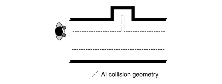
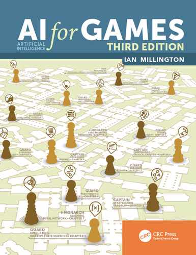
Figure 12.3: A crevice from automatic geometry widening
A solution is to use a separate AI geometry for the level shifted out from all walls by the radius of the character (assuming the character can be represented as a sphere or cylinder). This geometry allows collision detection to be calculated with point locations and lowers the cost of collision prediction and avoidance.
The calculation of this geometry is usually done automatically with a geometric algorithm. Unfortunately, these algorithms often have the side effect of introducing very small polygons in corners or crevices which can trap a character. Figure 12.3 shows a case where the geometry can give rise to a fine crevice that is likely to cause problems for an agent.
For very complex level geometries, an initial simplified collision geometry or support for visualization and modification of the AI geometry in the modeling package may be required.
Obstacle Representation
AI does not work efficiently with the raw polygon geometry of the level. Detecting obstacles by searching for them geometrically is a time-consuming task that always performs poorly.
Collision geometry is often a simplified version of the rendering geometry. Many developers use AI that searches based on the collision geometry.
Often, additional AI geometry needs to be applied to the obstacle so it can be avoided cleanly. The complex contours of an object do not matter to a character that is trying to avoid it altogether. As in Figure 12.4, a bounding sphere around the whole would be sufficient.
As the environment becomes more complex, the constraints on character movement are increased. Whereas moving through a room containing one crate is easy (no matter where the crate is), finding a path through a room strewn with crates is harder. There may be routes through the geometry that are excluded because the bounding spheres overlap. In this case, more complex AI geometry is required.

Figure 12.4: AI geometries: rendering, physics, and AI
Although originally designed for use in the movie industry, AI staging is increasingly being used for game effects. Staging involves coordinating movement-based game events.
Typically, the level designer places triggers in the game level that will switch on or off certain characters. The character AI will then begin to make the characters act correctly. Historically, this has often been observable to the player (characters suddenly coming to life when the player approaches), but now is generally better hidden from sight.
Staging takes this one stage further and allows the level designer to set high-level actions for the characters in response to triggers. Typically, this applies when there are many different AI characters in the scene (such as a swarm of spiders or a squad of soldiers).
The actions set in this way are overwhelmingly movement related. This is implemented as a state in the character’s decision making tool where it will execute a parametric movement (usually “move to this location,” with the location being the parameter). This parameter can then be set in the staging tool, either directly or as a result of a trigger during the game.
More sophisticated staging requires more complex sets of decisions. It can be supported with a more complete AI design tool, capable of modifying the decision making of a character. Changes to the internal state of the character can then be requested as a result of triggers in the level.
12.3 KNOWLEDGE FOR DECISION MAKING
At the simplest level, decision making can be implemented entirely by polling the game world for information. A character that needs to run away when faced with danger, for example, can look around for danger at each frame and run if the check comes back true. This level of decision making was common in games until the turn of the century.
Most modern games use some kind of message passing system to moderate communication. The character will stand around until it is told that it can see danger, whereupon it will run away. In this case the decision as to “what is dangerous” doesn’t depend on the character; it is a property of the game as a whole.
This allows the developer to design a level in which completely new objects are created, marked as dangerous, and positioned. The character will correctly respond to these objects and run away, without requiring additional programming. The message passing algorithm and the character’s AI are constant.
The toolchain needs to support this kind of object-specific data. The level designer will need to mark up different objects for the AI to understand their significance. Often, this isn’t an AI-specific process. A power-up in a platform game, for example, needs to be marked as collectible so the game will correctly allow the player to move into it (as opposed to making it impenetrable and having the player bounce off it). This “collectible” flag can be used by the AI: a character could be set so that it defends any remaining collectibles from the player.
Most toolchains are data driven: they allow users to add additional data to an object’s definition. These data can be used for decision making.
In some games, the actions available to a player depend on the objects in the player’s vicinity—for example, being able to push a button or pull a lever. In games with more complex decision making, the character may be able to use a range of gadgets, technologies, and everyday objects. A character may use a table as a shield or a paperclip to open a lock, for example.
While most games still reserve this level of interaction for the player, people simulation games lead a trend toward wider adoption of characters with broad competencies.
To support this, objects need to tell the character what actions they are capable of supporting. A button may only be pushed. A table may be climbed on, pushed around, thrown, or stripped of its legs and used as a shield. At its simplest, this can be achieved with additional data items: all objects can have a “can be pushed” flag, for example. Then a character can simply check the flag.
But this level of decision making is usually associated with goal-oriented behavior, where actions are selected because the character believes they will help achieve a goal. In this case, knowing that both buttons and tables can be pushed doesn’t help. The character doesn’t understand what will happen when such an action is performed and so can’t select an action to further its goals.
Pushing a button in an elevator does a very different thing than pushing a table under a hole in the roof; they achieve very different goals. To support goal-oriented behavior, or any kind of action planning, objects need to communicate the meaning of an action along with the action itself. Most commonly, this meaning is simply a list of goals that will be achieved (and those that will be compromised) if the action is taken.
Toolchains for games with goal-oriented AI need to treat actions as concrete objects. An action, like a game object in a regular game, can have data associated with it. These data include the change in the state of the world that will result from carrying out the action, along with prerequisites, timing information, and what animations to play. The actions are then associated with objects in the level.
So far I have outlined the tool requirements of individual AI techniques. To put a whole game together, these individual functions need to be marshaled so all the game data can be created and brought into the compiled game. The process of exposing these different editing functions, and combining the results together, is known as the ‘toolchain’: the chain of tools required to make a finished game.
Historically, through to the early 2000s, developers most commonly used a range of different tools, combined with scripts and common file formats to perform the integration. Game engine vendors began to realize that the toolchain was a key pain point for developers, and solutions involving integrated editors began to arise. The two most prominent game engines—Unreal Engine and Unity—are now by far the most widely used toolchains in the industry, and both provide integrated editing applications with extensible support for developer-defined tools. For most developers, the game engine and the editor form an integrated toolchain.
Most, that is, but not all. There are still some studios that prefer to build together a toolchain from different tools, to drive their in-house game engines. Not everyone wants to use an engine such as Unity, and if the engine isn’t being used, there is little reason to use the tooling.
This section takes a brief walk through the AI-related elements of a complete toolchain, for both users of prominent game engines and those choosing to go it alone. It considers a range of solutions from custom extensions for game engine editors, through independent behavior editing tools, to plug-ins for 3D modeling software.
12.4.1 INTEGRATED GAME ENGINES
At the start of the chapter, I briefly mentioned Renderware Studio, an early complete toolchain and editing application for the licensable Renderware engine (which was purchased as in-house technology and taken off the market by Electronic Arts in 2004). Its primary competitors Gamebryo and Unreal Engine also added integrated editors of their own, along with many integrated systems in-house at larger developers. But these engines capable of developing cutting-edge games were marketed at established development studios, with licensing terms and costs to match.
It was Unity, from 2005 onward, that lowered barriers to use and brought the same advantages to a larger market of studios, eventually supporting a growing industry of independent game developers and hobbyists. Although originally being Mac-only, and facing competition from other PC-centric integrated game tools, Unity undeniably won. It is now the most widely used game engine in the world, with millions of developers (possibly tens of millions, up-to-date numbers are difficult to acquire) and its model of an extensible level editor has become the de facto standard.
Built-in Tools
Unity and similar engines (Unreal Engine is the most common, but at the time of writing there is also the open source Godot, and other commercial offerings such as Amazon Lumberyard and CryEngine) provide a basic set of tools out of the box in their editor applications.
At their simplest, it is possible to associate additional data with objects in the level. Custom data slots can be defined, and the level author can fill these slots with data. This could include the value of a pickup, the navigation difficulty of a surface, or the placement of a cover point. All engines support objects that do not appear to the user, which can be used to hold global data, for all characters to access; or placed invisibly into a scene to represent a waypoint, or other localized piece of information. These tools are usually simple lists of key-value pairs where the value can be edited by the level author.
Both Unity and Unreal Engine provide inbuilt support for pathfinding and navigation. And both expose this in the editor, allowing the pathfinding data to be visualized and modified.
In addition, a custom state machine editor is usually provided for fine tuning animation. The resulting state machines can be accessed programmatically, and can be used as the basis of state machine AI. Though, because they are not optimized for this purpose, they may be overly cumbersome compared to a dedicated plug-in (see below).
Additional tools are provided for non-AI applications such as particle effects, sound mixing and font support, but typically no first-class tool support is provided for AI beyond navigation. For this, a plug-in is needed.
Editor Plug-ins
Game engine vendors cannot anticipate all the requirements of every game built using their system. Instead they support plug-in systems, where custom code can overlay data onto the main level view, or be given exclusive access to a window in which to draw their own user interface.

Figure 12.5: A screenshot of Behavior Designer by Opsive, a behavior tree editing tool for Unity.
The tool requirements in the rest of this section are typically implemented as plug-ins to modify the behavior of the editor. Both Unreal Engine and Unity have a large online store for developers to sell their plug-ins. Chances are, a tool is already available in the store that approximates the needs of your game. Though it may need tweaking, it can at least be used for rapid prototyping and as inspiration for a more customized solution.
Figure 12.5 shows a screenshot of such a tool focused on creating and running behavior trees.
Editor Scripting
Much of the power of integrated editors comes from their scripting language. Integrated scripting avoids the need to implement all game logic in a low-level language such as C++. As described in the next chapter, the ability to write code snippets reduces the need for the simpler decision-making AI techniques. Rather than a decision tree, built using a decision tree editing tool, a script with a list of if-statements can have the same effect.
If written in source code, scripts require a programmer to author. This may be fine for an indie studio where a game designer is also tasked with programming the game, but in larger teams with more specialization, it may not be feasible. Fortunately, there are more friendly alternatives within reach of technically minded non-programmers.
Out of the box, Unreal Engine (beginning in version 4) supports Blueprints, a visual programming language, with much of the flexibility of a tool for creating AI state machines, behavior trees or decision trees. Similar tools are available in the Unity asset store. At the time of writing, Playmaker by Hutong Games LLC is the most popular, though there are several alternatives.
Section 13.3 in Chapter 13 looks at such visual scripting languages in more detail.
12.4.2 CUSTOM DATA-DRIVEN EDITORS
Developers using their own engine must factor in the creation of custom editors to prepare their data.
AI isn’t the only area in which a huge amount of extra data is required for a game level. The game logic, physics, networking, and audio require their own sets of information. It is possible to create several separate tools to generate this data, but most developers follow the Unity or Unreal model and bring all editing functions into one application. This can then be reused over all their games. Ownership of such a tool provides the flexibility to implement complex editing functionality tightly integrated with the final game code, in a way that would be difficult in an existing editor.
A former client of mine adopted this approach because their game engine relied on memory-mapped level data, where all the information required to play a level (models, textures, AI, sound, etc.) were stored laid out in memory in exactly the way their C++ code needed it, improving loading times to the point where new sections of a level could be loaded in the background during gameplay. Existing engine editors were too opinionated about how they store their data, so the company developed their own from scratch.
Whatever the motivation, this kind of complete level editing package is often called “data driven” or “object oriented.” Each object in the game world has a set of data associated with it. This set of data controls the behavior of the object—the way in which it is treated by the game logic.
It is relatively easy to support the editing of AI data in this context. Often, it is a matter of adding a handful of extra data types for each object (such as marking certain objects as “to be avoided” and other objects as “to be collected”).
Creating tools of this kind is a major development project and is not an option for small studios, self-publishing teams, or hobbyists. Even for teams with such a tool, there are limitations to the data-driven approach. Creating a character’s AI is not just a matter of setting a bunch of parameter values. Different characters require different decision making logic and the ability to marshal several different behaviors to select the right one at the right time. This requires a specific AI design tool (although such tools are often integrated into the data-driven editor).
In the same way that modern game engines provide certain tools as standard (namely the ability to mark up a level and navigation tools), the most common custom tools enable the AI to understand the game level better and to get access to the information it needs to make sensible decisions.
As the sophistication of AI techniques increases, and level designers are tasked with implementing more behavior, developers are looking at ways to allow level designers to have access to the AI of characters they are placing. Level designers creating an indoor lab scenario, for example, may need to create a number of different guard characters. They will need to give them different patrol routes, different abilities to sense intruders, and different sets of behaviors when they do detect the player.
Allowing the level designers to have this kind of control requires specialist AI design tools. Without a tool, the designer has to rely on programmers to make AI modifications and set up characters with their appropriate behaviors.
Scripting Tools
The first tools to support this kind of development were based on scripting languages. Scripts can be edited without recompilation and can often be easily tested. Many game engines that support scripting provide mechanisms for editing, debugging, and stepping through scripts. This has been primarily used to develop the game level logic (such as doors opening in response to button presses, and so on). But, as AI has evolved from this level, scripting languages have been extended to support it.
Scripting languages suffer from the problem of being programming languages. Nontechnical level designers can have difficulty developing complex scripts to control character AI.
State Machine Designers
By the mid-2000s, tools supporting the combination of pre-built behaviors became widely available. Some commercial middleware tools fall under this category, such as Havok’s AI support, as well as several open source and in-house tools created by large developers and publishers. These tools allow a level designer to combine a palette of AI behaviors.
A character may need to patrol a route until it hears an alarm and investigates, for example. The “patrol route” and “investigate” behaviors would be created by the programming team and exposed to the AI tool. The level designer would then select them and combine them with a decision making process that depends on the state of the siren.
The actions selected by the level designer are often little more than steering behaviors. As discussed in Chapter 3, this is often all that is required for the majority of game character behavior.

Figure 12.6: The SimBionic editor screen
The decision making process favored by this approach is state machines, with the behavior trees a more sophisticated minority option. Figure 12.6 shows a screenshot of the SimBionic FSM tool, originally a commercial middleware offering, now open source.
The best tools of this type have incorporated the debugging support of a scripting language, allowing the level editors to step through the operation of the FSM, seeing visually the current state of a character and being able to manually set their internal properties.
Getting information out of the game at runtime is crucial for diagnosing the kind of AI problem that doesn’t show in isolated tests. Typically, developers add debugging code to report the internal state of the game as it is played. This can be displayed on-screen or logged to file and analyzed for the source of errors.
When running on a PC, it is relatively easy to get inside the running game. Debugging tools can attach to the game and report details of its internal state. On consoles and mobile devices, remote debugging tools exist to connect from the development PC to the test hardware.
While there is a lot that can be done with this kind of inspection, more sophisticated debugging tools are almost always required for anything but the simplest games. Analyzing memory locations or the value of variables is useful for some debugging tasks. But it is difficult to work out how a complex state machine is responding and impossible to understand the performance of a neural network.
A debugging tool can attach to a running game to read and write data for the AI (and any other in-game activity, for that matter). One of the most common applications of remote debugging is the visualization of internal AI state, whether the decisions of the behavior tree, the output of a neural network, or the line of sight tests being performed by sense management. Often, combined with the tools that edit this data, this allows the developer to see and tweak the characters in the game as they run, and sometimes even introduce specific events into an event management mechanism.
Remote debugging requires a debugging application to be running on a PC, communicating over the network to the game, or running on another PC, mobile device or console (or sometimes the same PC). This network communication can cause problems with data reliability and timing (the state of the game may have moved on from what the developer is looking at). Although this has improved in the last decade with the movement of all platforms to always-on internet connectivity, some legacy devices do not support general network communication suitable for this kind of tool.
Internet connected platforms also open the opportunity to access debugging information running on players’ machines after the game is released. There can be legal issues of privacy, but this has become a standard tool many developers use to optimize their game in successive patches. Several turnkey solutions are available for in-game analytics, particularly on mobile devices.
Although custom level editing tools are now almost ubiquitous, 3D design, modeling, and texturing are still overwhelmingly performed in a high-end modeling package like Autodesk’s 3ds Max or Maya, with the open source Blender package popular among smaller independent and hobbyist developers.
Each of these tools has a programmer’s software development kit (SDK) that allows new functionality to be implemented in the form of plug-in tools. This allows developers to add plug-in tools for capturing AI data. Plug-ins written with the SDK are packaged into libraries. They are sometimes written in C/C++, but more commonly in a scripting language provided by the package (for example MAXScript for 3DS Max, and Python for Blender).
The internal operation of each software package puts significant constraints on the architecture of plug-ins. It is challenging to integrate with the existing tools in the application, and can be non-intuitive to connect to the undo system, the software’s user interface, and the internal format of its data. Because each tool is so radically different and the SDKs each have a very different architecture, what you learn developing for one often will not translate.
For AI support, the candidates for plug-in development are the same as the functionality required in a level editing tool. Because there has been such a substantial shift toward dedicated level editing tools, fewer developers are building AI plug-ins for 3D modeling software.
EXERCISES
12.1 Develop a tool that can analyze the placement of waypoints in level geometry and recognize potential problems like the ones illustrated in Figure 12.1. Note that you are not being asked to place the waypoints automatically or resolve problems, just identify them. For the geometry you can, at least to start with, just use a simple grid.
12.2 Perform a post-processing step to simplify the links in the graph shown in Figure 12.7.
12.3 Figure 12.8 shows a visual representation of a log file of the type that might be generated by recording areas of a level that get visited during a play session.
What problems might occur if this log file was used to automatically generate a waypoint graph? What additional information could be recorded in the log file to fix the problem?
12.4 Figure 12.9 shows two alternative representations that an AI character might use for an enemy standing on a bridge. The representation on the left uses waypoints and the one on the right a navigation mesh.
What kind of problems might occur with the waypoint representation and how might the navmesh fair better in this regard?
Figure 12.7: A dense graph representing a simple room

Figure 12.8: Visited locations in a level

Figure 12.9: Alternative representations for the same situation