
CHAPTER 2
TCP/IP CONCEPTS REVIEW
After reading this chapter and completing the activities, you will be able to:
![]() Explain the TCP/IP protocol stack
Explain the TCP/IP protocol stack
![]() Explain the basic concepts of IP addressing
Explain the basic concepts of IP addressing
![]() Explain the binary, octal, and hexadecimal numbering systems
Explain the binary, octal, and hexadecimal numbering systems
Almost everything you do as a network security analyst or security tester depends on your understanding of networking concepts and knowledge of Transmission Control Protocol/Internet Protocol (TCP/IP). It’s assumed you already understand networking concepts and TCP/IP and are CompTIA Network+ certified or have equivalent knowledge. This chapter, however, serves as a review of how these topics relate to IT security and security testers. In the activities and case projects, you apply your knowledge of TCP/IP and networking concepts to security-testing techniques.
Most of the tools both hackers and security testers use run over IP, which is a standard networking protocol. However, IP version 4 (IPv4), still the most widely used version, was developed without security functions in mind, so professionals need the knowledge and skills to tighten up security holes resulting from the use of IP.
In this chapter, you examine the TCP/IP protocol stack and IP addressing and review the binary, octal, and hexadecimal numbering systems and the ports associated with services that run over TCP/IP.
OVERVIEW OF TCP/IP
For computers to communicate with one another over the Internet or across an office, they must speak the same language. This language is referred to as a protocol, and the most widely used is Transmission Control Protocol/Internet Protocol (TCP/ IP). No matter what medium connects workstations on a network—copper wires, fiber-optic cables, or a wireless setup—the same protocol must be running on all computers if communication is going to function correctly. In a Japanese restaurant, sticking your chopsticks in the rice bowl after eating is considered a major error in protocol. Similarly, attempting to have a computer running Novell’s Internetwork Packet Exchange/Sequenced Packet Exchange (IPX/SPX) protocol connect to a Windows Server 2003 server running TCP/IP would produce a protocol error that prevents network communication and keeps users from connecting to the server.
Security Bytes
Even though IPX/SPX isn’t widely used today, many corporations have legacy systems that rely on it. In fact, some users separate internal networks from the outside world by running IPX/SPX internally. An intruder attempting to attack a network over the Internet would be blocked when the protocol changed from TCP/IP to IPX/SPX. This tactic is referred to as “the poor man’s firewall.” Of course, it’s not a recommended solution for protecting a network, but as a network security professional, you might see it used.
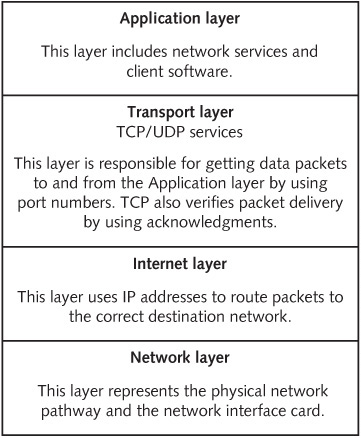
You’ve probably already studied TCP/IP, but a little review is helpful to make sure you have a thorough understanding. TCP/IP is more than simply two protocols (TCP and IP). It’s usually referred to as the TCP/IP stack, which contains four distinct layers (see Figure 2.1). The Network layer is concerned with physically moving electrons across a medium (whether it’s copper wire, fiber-optic cables, or wireless), and the Internet layer is responsible for routing packets by using IP addresses. The Transport layer is concerned with controlling the flow of data, sequencing packets for reassembly, and encapsulating the segment with a TCP or User Datagram Protocol (UDP) header. The Application layer is where applications and protocols, such as HTTP and Telnet, operate.
This chapter discusses only the Application, Transport, and Internet layers, covered in the following sections, because security testing doesn’t usually involve getting down to the Network layer’s hardware level. However, there are computer attacks that use physical hardware, such as a keylogger (covered in Chapter 3).
The Application Layer
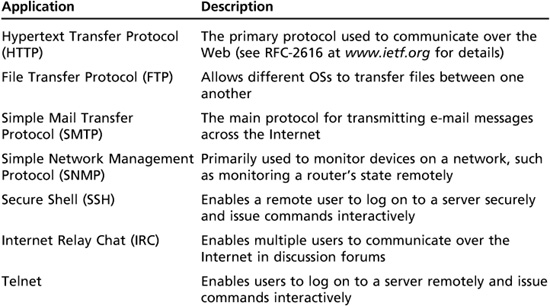
The Application-layer protocols are the front end to the lower-layer protocols in the TCP/IP stack. In other words, this layer is what you can see and touch. Table 2.1 lists some of the main applications and protocols running at this layer. These applications and protocols are mentioned again later in “TCP Ports.”
Figure 2.1
The TCP/IP protocol stack
Courtesy Course Technology/Cengage Learning
Table 2.1 Application layer programs
The Transport Layer
The Transport layer is where data is encapsulated into segments. A segment can use TCP or UDP as its method for connecting to and forwarding data to a destination host (or node). TCP is a connection-oriented protocol, meaning the sender doesn’t send any data to the destination node until the destination node acknowledges that it’s listening to the sender. In other words, a connection is established before data is sent. For example, if Computer A wants to send data to Computer B, it sends Computer B a SYN packet first. A SYN packet is a query to the receiver, much like asking “Hello, Computer B. Are you there?” Computer B sends back an acknowledgment called a SYN-ACK packet, which is like replying “Yes, I’m here. Go ahead and send.” Finally, Computer A sends an ACK packet to Computer B in response to the SYN-ACK. This process, called a three-way handshake, involves the following steps:
1. Host A sends a TCP packet with the SYN flag set (that is, a SYN packet) to Host B.
2. After receiving the packet, Host B sends Host A its own SYN packet with an ACK flag (a SYN-ACK packet) set.
3. In response to the SYN-ACK packet from Host B, Host A sends Host B a TCP packet with the ACK flag set (an ACK packet).
TCP Segment Headers
As a security professional, you should know the critical components of a TCP header: TCP flags, the initial sequence number (covered later in “Initial Sequence Number”), and source and destination port numbers (covered later in “TCP Ports”). Hackers abuse many of these TCP header components; for example, when port scanning, many hackers use the method of sending a packet with a SYN-ACK flag set, even though a SYN packet wasn’t sent first. Security testers also use this method but for legitimate purposes. You need to understand these components before learning how they can be abused. Then, and only then, can you check whether your network has vulnerabilities in these areas. Remember, to protect a network, you need to know the basic methods of hacking into networks. You examine more details on TCP headers in Activity 2.1.
TCP Flags
Each TCP flag occupies one bit of the TCP segment and can be set to 0 (off) or 1 (on). These are the six flags of a TCP segment:
![]() SYN flag—The synch flag signifies the beginning of a session.
SYN flag—The synch flag signifies the beginning of a session.
![]() ACK flag—The acknowledgment flag acknowledges a connection and is sent by a host after receiving a SYN-ACK packet.
ACK flag—The acknowledgment flag acknowledges a connection and is sent by a host after receiving a SYN-ACK packet.
![]() PSH flag—The push flag is used to deliver data directly to an application. Data isn’t buffered; it’s sent immediately.
PSH flag—The push flag is used to deliver data directly to an application. Data isn’t buffered; it’s sent immediately.
![]() URG flag—This flag is used to signify urgent data.
URG flag—This flag is used to signify urgent data.
![]() RST flag—The reset flag resets or drops a connection.
RST flag—The reset flag resets or drops a connection.
![]() FIN flag—The finish flag signifies that the connection is finished.
FIN flag—The finish flag signifies that the connection is finished.
Initial Sequence Number
The initial sequence number (ISN) is a 32-bit number that tracks packets received by a node and allows reassembling large packets that have been broken up into smaller packets. In Steps 1 and 2 of the three-way handshake, an ISN is sent. That is, the ISN from the sending node is sent with the SYN packet, and the ISN from the receiving node is sent back to the sending node with the SYN-ACK packet. An ISN can be quite a large number because 232 allows a range of numbers from zero to more than four billion.
Security Bytes
A TCP header’s ISN might not seem important to network security professionals who aren’t familiar with penetration testing or hacking techniques. In fact, most people ignore many of these fundamental concepts. However, numerous network attacks have used session hijacking, an attack that relies on guessing the ISNs of TCP packets. One of the most famous is Kevin Mitnick’s attack on the Japanese corporation Tsutomu Shimomura, called an IP sequence attack. Understanding TCP flags and the basic elements of a TCP packet can go a long way toward understanding how a hacker thinks—and how you should think. To become a better security professional, try to discover vulnerabilities or weaknesses as you study the basics. Too many network security professionals wait for hackers to discover vulnerabilities in a network instead of beating them at their own game.
Time Required: 30 minutes
Objective: Examine the details of components of a TCP segment and how to make use of Request for Comments (RFC) documents.
Description: As an IT security professional, the amount of available information can be overwhelming. To protect corporate resources (or “assets,” as they’re commonly called), you’re expected to be skillful in many areas. To gain the necessary skills, you should know where to look for technical information that helps you better understand a particular technology. Want to know how the Domain Name System (DNS) works? Want a better understanding of Dynamic Host Configuration Protocol (DHCP)? Reading the RFCs on these topics can answer any questions you might have. In this activity, you examine the details of a TCP segment and get an overview of some TCP header components. You don’t have to memorize your findings. This activity is merely an introduction to the wonderful world of RFCs.
1. Start your Web browser, and go to www.ietf.org.
2. On the Internet Engineering Task Force home page, click the RFC Pages link on the left. (If time permits, you might want to navigate to the many other selections for information on useful topics.)
3. Read the instructions on the Request for Comments page, and then type 793 in the RFC number text box and click go. Note the title page of this RFC.
4. Scroll down the document and read the table of contents to get an overview of this document’s information. Read Sections 2.6, 2.7, and 2.8 to get a better idea of how TCP works. (Note that Section 2.6 discusses reliable communication.)
5. Scroll down to Section 3.1, “Header Format.” The diagram might not be what you’re used to seeing in computer documentation, but it’s typical of what you see in an RFC. The numbers at the top make it easier for you to see the position of each bit. For example, the upper 0, 1, 2, and 3 show you that there are a total of 32 bits (0 to 31) across this segment. Note that the source port and destination port fields are 16 bits long, and both the ISN and the acknowledgment number are 32 bits long.
6. Read Section 3.1, and note the use of the binary numbering system. This information should help solidify your knowledge of binary and hexadecimal numbering. These topics are also reviewed in “Overview of Numbering Systems” later in the chapter.
7. Scroll down to Section 3.4, “Establishing a connection,” and skim the description of a three-way handshake. The author does a nice job of simplifying this process and adds a little humor about why an ACK doesn’t occupy sequence number space. Many RFC authors have a knack for explaining complex material in an easy-to-understand manner.
8. Scroll through the rest of the document to get an overview of what’s covered. You can read the entire document later, if you like. When you’re finished, exit your Web browser.
TCP Ports
A TCP packet has two 16-bit fields containing the source and destination port numbers. A port is the logical, not physical, component of a TCP connection. A port identifies the service that’s running. For example, the HTTP service uses port 80 by default. Understanding ports is important so that you know how to stop or disable services that aren’t being used on your network. The more services you have running on a server, the more ports are open for a potential attack. In other words, securing a house with 1000 open doorways is more difficult than securing a house with only 10 open doorways.
The most difficult part of a network security professional’s job is balancing system security with ease of use and availability for users. Closing all ports and stopping all services would certainly make your network more secure, but your users couldn’t connect to the Internet, send or receive e-mail, or access any network resources. So your job is to allow users to work in a secure network environment without preventing them from using services such as e-mail, Web browsing, and the like. This task isn’t easy, as you’ll see throughout this book.
A possible 65,535 TCP and UDP port numbers are available, but the good news is that only 1023 are considered well-known ports. To see the list of well-known ports, visit the Internet Assigned Numbers Authority (IANA) at www.iana.org. There’s probably more information than you need, but navigating around this Web site gives you practice in searching for information. A good security professional knows how to be persistent in looking for answers by using a structured methodology.
Tip
You can access the page about well-known ports by entering www.iana.org/assignments/port-numbers as the URL, but you bypass the IANA home page, which has more information and access to the IANA Whois service. This service is covered later in Chapter 4, but you can review it while browsing the IANA page.
Don’t worry about memorizing these 1023 ports. Luckily, that isn’t necessary. However, you should memorize the following TCP ports and the services they represent. Much of what you do as a security professional and penetration tester relies heavily on understanding this information.
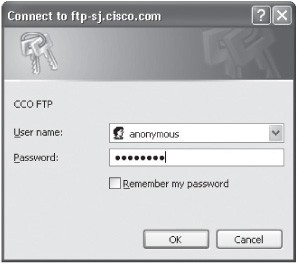
![]() Ports 20 and 21 (File Transfer Protocol)—FTP has been around as long as the Internet. It was the standard for moving or copying large files and is still used today, although to a lesser extent because of the popularity of HTTP (covered later in this section). FTP uses port 20 for data transfer and port 21 for control. FTP requires entering a logon name and password and is more secure than Trivial File Transfer Protocol (TFTP; covered later in this list). Figure 2.2 shows the logon window displayed when attempting to connect to a Cisco FTP site.
Ports 20 and 21 (File Transfer Protocol)—FTP has been around as long as the Internet. It was the standard for moving or copying large files and is still used today, although to a lesser extent because of the popularity of HTTP (covered later in this section). FTP uses port 20 for data transfer and port 21 for control. FTP requires entering a logon name and password and is more secure than Trivial File Transfer Protocol (TFTP; covered later in this list). Figure 2.2 shows the logon window displayed when attempting to connect to a Cisco FTP site.
![]() Port 25 (Simple Mail Transfer Protocol)—E-mail servers listen on this port. If you attempt to send e-mail to a remote user, your workstation connects to port 25 on a mail server.
Port 25 (Simple Mail Transfer Protocol)—E-mail servers listen on this port. If you attempt to send e-mail to a remote user, your workstation connects to port 25 on a mail server.
![]() Port 53 (Domain Name System)—If a server on your network uses DNS, it’s using port 53. Most networks require a DNS server so that users can connect to Web sites with URLs instead of IP addresses. When a user enters a URL, such as www.yahoo.com, the DNS server resolves the name to an IP address. The DNS server might be internal to the company, or each computer might be configured to point to the IP address of a DNS server that’s serviced by the company’s ISP.
Port 53 (Domain Name System)—If a server on your network uses DNS, it’s using port 53. Most networks require a DNS server so that users can connect to Web sites with URLs instead of IP addresses. When a user enters a URL, such as www.yahoo.com, the DNS server resolves the name to an IP address. The DNS server might be internal to the company, or each computer might be configured to point to the IP address of a DNS server that’s serviced by the company’s ISP.
Figure 2.2
Connecting to an FTP site
Courtesy Course Technology/Cengage Learning
![]() Port 69 (Trivial File Transfer Protocol)—Many network engineers use the TFTP service to transfer router and backup router configurations.
Port 69 (Trivial File Transfer Protocol)—Many network engineers use the TFTP service to transfer router and backup router configurations.
![]() Port 80 (Hypertext Transfer Protocol)—Most certification exams have a question about port 80 being used for HTTP. Port 80 is used when you connect to a Web server. If security personnel decided to filter out HTTP traffic, almost every user would notice a problem on the network.
Port 80 (Hypertext Transfer Protocol)—Most certification exams have a question about port 80 being used for HTTP. Port 80 is used when you connect to a Web server. If security personnel decided to filter out HTTP traffic, almost every user would notice a problem on the network.
Security Bytes
Often technical personnel who aren’t familiar with security techniques think that restricting access to ports on a router or firewall can protect a network from attack. This is easier said than done. After all, if a firewall prevents any traffic from entering or exiting a network on port 80, you have indeed closed a vulnerable port to access from hackers. However, you have also closed the door to Internet access for your users, which probably isn’t acceptable in your company. The tricky (and almost impossible) part for security personnel is attempting to keep out the bad guys yet allow the good guys to work and use the Internet. As you progress through this book, you’ll see that as long as users can connect to the Internet through an open port, attackers can get in. It’s that simple. If a user can get out, an attacker can get in!
![]() Port 110 (Post Office Protocol 3)—To retrieve e-mail from a mail server, you most likely access port 110. An enhanced e-mail retrieving protocol, IMAP4, is also available and is covered later in this list. POP3 is still around, however, and is one of the most common e-mail retrieval systems.
Port 110 (Post Office Protocol 3)—To retrieve e-mail from a mail server, you most likely access port 110. An enhanced e-mail retrieving protocol, IMAP4, is also available and is covered later in this list. POP3 is still around, however, and is one of the most common e-mail retrieval systems.
![]() Port 119 (Network News Transport Protocol)—This port is used to connect to a news server for use with newsgroups.
Port 119 (Network News Transport Protocol)—This port is used to connect to a news server for use with newsgroups.
![]() Port 135 (Remote Procedure Call)—This port, used by Microsoft RPC, is critical for the operation of Microsoft Exchange Server as well as Active Directory, available in Windows 2000 Server and later.
Port 135 (Remote Procedure Call)—This port, used by Microsoft RPC, is critical for the operation of Microsoft Exchange Server as well as Active Directory, available in Windows 2000 Server and later.
![]() Port 139 (NetBIOS)—This port is used by Microsoft’s NetBIOS Session Service to share resources. NetBIOS is covered in detail in Chapter 8.
Port 139 (NetBIOS)—This port is used by Microsoft’s NetBIOS Session Service to share resources. NetBIOS is covered in detail in Chapter 8.
![]() Port 143 (Internet Message Access Protocol 4)—IMAP4 uses this port to retrieve e-mail.
Port 143 (Internet Message Access Protocol 4)—IMAP4 uses this port to retrieve e-mail.
Activity 2.2: Connecting to Port 25 (SMTP)
Time Required: 30 minutes
Objective: Use the Telnet command to access port 25 on your mail server, log on, and send an e-mail message to a recipient.
Description: As an IT security professional, you should be aware of the ports used in a network infrastructure. A good way to test whether a service is running on a server is to telnet to the port using that service. For example, the SMTP service uses port 25. In this activity, you telnet into your mail server from your Windows computer. If you don’t have a mail server configured, connect to your ISP’s mail server and send an e-mail from your e-mail account.
Note
If you can’t connect to a mail server with the commands in Activities 2.2 and 2.3, you should still read through the steps and examine the figures to give you an idea of what a successful Telnet connection looks like.
1. To open a command prompt window in Windows Vista and later, click Start, type cmd in the Start Search text box, and press Enter. (Note: In Windows XP, click Start, Run, type cmd in the Open text box, and press Enter.)
2. Type telnet RemoteMailServer 25 (substituting your own server name for RemoteMailServer) and press Enter. Note that you must enter the port number of the service you’re attempting to connect to. In this case, you use port 25 for SMTP. If you’re using Windows XP, skip to Step 4.
3. Telnet is disabled by default in Windows Vista and later, so if you’re running one of these OSs, you get an error message. Open Control Panel and click Programs and Features. On the left, click Turn Windows features on or off. In the Windows Features dialog box, scroll down and click the Telnet Client check box (see Figure 2.3). You can select other services you want to enable at this time, too. When you’re finished, click OK and close Control Panel.
4. After receiving the prompt shown in Figure 2.4, type helo LocalDomainName and press Enter. The mail server accepts almost anything you enter after the Helo command as valid, but you should use your actual domain name.
5. You can now enter your e-mail address, which is displayed in the recipient’s From field. You can enter a bogus address, as shown in Figure 2.4, which is how someone can spoof an e-mail, but you should enter your correct e-mail address for this activity. Type mail from: YourMailAccount and press Enter.
Figure 2.3
Enabling Telnet

Courtesy Course Technology/Cengage Learning
Figure 2.4
Using Telnet to send e-mail

Courtesy Course Technology/Cengage Learning
6. You should get a “250 OK” message. You can then enter the recipient’s e-mail address. (You can also send a message to yourself.) Type rcpt to: RecipientMailAccount and press Enter. You can enter a bogus address here, too, but the e-mail isn’t actually sent unless the RecipientMailAccount is valid.
7. After getting a “Recipient OK” message, you’re ready to start creating your message. Type data and press Enter. Type your message, press Enter, and then type a single period and press Enter to end your message. You should get a message saying that your e-mail was queued.
Tip
If you make a typo, you have to reenter your commands. Pressing Backspace or using the arrow keys doesn’t work.
8. To end the Telnet session, type quit and press Enter. The “Bye” message from the mail server is displayed, and then you see the “Connection to host lost” message shown in Figure 2.4.
9. You can leave the command prompt window open for the next activity.
Activity 2.3: Connecting to Port 110 (POP3)
Time Required: 30 minutes
Objective: Use the Telnet command to access port 110 on your mail server, log on, and retrieve an e-mail message that has been sent to your e-mail account.
Description: The POP3 service uses port 110. In this activity, you telnet to your mail server from your Windows computer. If you don’t have a mail server configured, connect to your ISP’s mail server and retrieve an e-mail message that has been sent to your mailbox.
1. Open a command prompt window, if necessary.
2. Type telnet RemoteMailServer 110 (substituting your server name for RemoteMailServer) and press Enter.
3. After getting the +OK message (see Figure 2.5), you must enter the user command for logging on to your account. Type user YourMailAccount and press Enter.
4. Next, you’re prompted to enter your password. Type pass YourPassword and press Enter.
5. After being authenticated by the mail server, you get a message similar to Figure 2.6 showing the number of messages in your mailbox. To list all the messages, type list and press Enter.
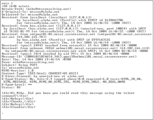
6. To retrieve a specific message, you use the Retr command followed by the message number. For example, to retrieve message number 1, type retr 1 and press Enter (see Figure 2.7).
7. Type quit and press Enter. This command deletes any messages marked for deletion, logs you off the mail server, and ends the Telnet session.
8. To view open ports on your Windows computer, you can use the Netstat command. Figure 2.8 shows the result of running Netstat while multiple ports are open. Open another command prompt window, type netstat, and press Enter.
Figure 2.5
Logging on to an e-mail server

Courtesy Course Technology/Cengage Learning
Figure 2.6
Viewing e-mail messages in a mailbox

Courtesy Course Technology/Cengage Learning
Figure 2.7
Retrieving an e-mail message
Courtesy Course Technology/Cengage Learning
Figure 2.8
Using the Netstat command to view open ports

Courtesy Course Technology/Cengage Learning
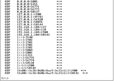
9. If the results show no active ports open, try typing netstat -a and pressing Enter. This command lists all connections and listening ports on your system (see Figure 2.9). Note the many TCP and UDP ports listed.
10. Minimize the command prompt window, and start your Web browser.
11. Connect to any Web site. Maximize the command prompt window, type netstat again, and press Enter. Note the new entry indicating that port 80 (HTTP) is now being used.
Figure 2.9
Using Netstat with the -a option

Courtesy Course Technology/Cengage Learning
12. Close the command prompt window and any other open windows.
User Datagram Protocol
User Datagram Protocol (UDP) is a fast but unreliable delivery protocol that also operates on the Transport layer. Imagine trying to compete in the mail courier business and touting that your service is fast but unreliable. It would probably be difficult to sell. However, UDP is a widely used protocol on the Internet because of its speed. It doesn’t need to verify whether the receiver is listening or ready to accept the packets. The sender doesn’t care—it just sends, even if the receiver isn’t ready to accept the packet. See why it’s faster? Some applications that use UDP have built-in utilities to warn recipients of undeliverable messages, but UDP doesn’t. In other words, it depends on the higher layers of the TCP/IP stack to handle these problems. Think of UDP as someone announcing over a loudspeaker that school will be closed that afternoon. Some lucky students will hear the message, and some won’t. This type of delivery protocol is referred to as connectionless.
The Internet Layer
The Internet layer of the TCP/IP stack is responsible for routing a packet to a destination address. Routing is done by using a logical address, called an IP address. Like UDP, IP addressing packet delivery is connectionless. IP addressing is covered in more detail later in “IP Addressing,” but first take a look at another protocol operating at the Internet layer.
Internet Control Message Protocol
Internet Control Message Protocol (ICMP) is used to send messages related to network operations. For example, if a packet can’t reach its destination, you might see the “Destination Unreachable” error.
ICMP makes it possible for network professionals to troubleshoot network connectivity problems (with the Ping command) and track the route a packet traverses from a source IP address to a destination IP address (with the Traceroute command). Security professionals can use ICMP type codes (see Table 2.2) to block ICMP packets from entering or leaving a network. For example, a router can be configured to not allow an ICMP packet with the type code 8 to enter a network. Try pinging www.microsoft.com and see what happens. Microsoft doesn’t allow its IP address to be pinged, which is the type code 8 (Echo).
Tip
For a more detailed description of ICMP, see RFC-792.
IP ADDRESSING
An IP address consists of 4 bytes divided into two components: a network address and a host address. Based on the starting decimal number of the first byte, you can classify IP addresses as Class A, Class B, or Class C, as shown in Table 2.3.


Table 2.3 TCP/IP address classes

Note
The 127 address missing from Table 2.3 is used for loopback and testing. It’s not a valid IP address that can be assigned to a network device. Class D and Class E addresses are reserved for multicast and experimental addressing and aren’t covered in this chapter.
From Table 2.3, you can determine, for example, that a user with the IP address 193.1.2.3 has a Class C address, and a user with the IP address 9.1.2.3 has a Class A address. An IP address is composed of 4 bytes (an octet). A byte is equal to 8 bits, which also equals an octet, so you sometimes see an IP address defined as four octets instead of 4 bytes. The following list describes each address class:
![]() Class A—The first byte of a Class A address is reserved for the network address, making the last 3 bytes available to assign to host computers. Because a Class A address has a three-octet host address, Class A networks can support more than 16 million hosts. (For more information on determining how many hosts a network can support, see “Reviewing the Binary Numbering System” later in this chapter.) The number of Class A addresses is limited, so these addresses are reserved for large corporations and governments. Class A addresses have the format network.node.node.node.
Class A—The first byte of a Class A address is reserved for the network address, making the last 3 bytes available to assign to host computers. Because a Class A address has a three-octet host address, Class A networks can support more than 16 million hosts. (For more information on determining how many hosts a network can support, see “Reviewing the Binary Numbering System” later in this chapter.) The number of Class A addresses is limited, so these addresses are reserved for large corporations and governments. Class A addresses have the format network.node.node.node.
![]() Class B—These addresses are divided evenly between a two-octet network address and a two-octet host address, allowing more than 65,000 hosts per Class B network address. Large organizations and ISPs are often assigned Class B addresses, which have the format network.network.node.node.
Class B—These addresses are divided evenly between a two-octet network address and a two-octet host address, allowing more than 65,000 hosts per Class B network address. Large organizations and ISPs are often assigned Class B addresses, which have the format network.network.node.node.
![]() Class C—These addresses have a three-octet network address and a one-octet host address, resulting in more than 2 million Class C addresses. Each address supports up to 254 hosts. These addresses, usually available for small businesses and home use, have the format network.network.network.node.
Class C—These addresses have a three-octet network address and a one-octet host address, resulting in more than 2 million Class C addresses. Each address supports up to 254 hosts. These addresses, usually available for small businesses and home use, have the format network.network.network.node.
In addition to a unique network address, each network must be assigned a subnet mask, which helps distinguish the network address bits from the host address bits. As a security professional, you should understand subnetting, which is covered in the Network+ curriculum. Many utilities return information based on IP address and subnet information, so a thorough understanding of these concepts is important. In addition, when conducting a penetration test, you might be required to determine which hosts are on a specific network segment, so be sure to review this topic if you’re not familiar with subnetting networks or recognizing when a network is subnetted.
Planning IP Address Assignments
When IP addresses are assigned, companies need to assign a unique network address to each network segment that’s separated by a router. For example, a company has been issued two IP addresses: 193.145.85.0 and 193.145.86.0. Looking at the first byte of each address, the company determines that both are Class C addresses. With a default subnet mask of 255.255.255.0, 254 host addresses can be assigned to each segment. You use the formula 2x − 2 for this calculation, with x representing the number of unmasked bits. For this example, x equals 8 because there are 8 bits in the fourth octet:
28 − 2 = 254
You must subtract 2 in the formula because the network portion and host portion of an IP address can’t contain all 1s or all 0s. Remember, you can’t assign a network user the IP address 192.168.8.0 if you used the 255.255.255.0 mask. Also, you can’t give a user an address of 192.168.8.255 because it would produce all 1s in the host portion of an IP address; this address is reserved as a broadcast address to all nodes on the segment 192.168.8.0.
To access entities and services on other networks, each computer must also have the IP address of its gateway. Before sending a packet to another computer, the TCP/IP Internet layer uses the sending computer’s subnet mask to determine the destination computer’s network address. If this address is different from the sending computer’s network address, the sending computer relays the packet to the IP address specified in the gateway parameter. The gateway computer then forwards the packet to its next destination. In this way, the packet eventually reaches the destination computer.
For example, if a Linux server has the IP address 192.168.8.2 and the subnet mask 255.255.255.0, and a user has a computer with the IP address 192.168.9.200 and the subnet mask 255.255.255.0, the company must configure a default gateway address. The default gateway sends the message to a router, which routes it to the different network segment. If the default gateway isn’t configured on the user’s computer, and this user attempts to use the Ping command to contact the server, he or she gets the “Destination Unreachable” message (see Table 2.2). The user’s computer can’t connect to the other host—a Linux server located on a different network segment—because there’s no router to help it. The router’s job is to take packets destined for a computer on a different network segment from the sending computer and send them on their way.
As a security professional, you must understand these basic network concepts before attempting to conduct a penetration test on a network, especially one that’s been sub-netted. In a subnetted network, it might be easy to mistake a broadcast address as a valid host address, a major blunder that could cause a denial-of-service attack after thousands of packets are sent to all hosts on a network instead of to the one host you were trying to reach. Just be sure to verify the IP address you’re sending packets to before pressing Enter!
IPv6 Addressing
As a security professional, you should spend some time reviewing the IP addressing system Internet Protocol version 6 (IPv6). As mentioned, IPv4 wasn’t designed with security in mind, and many current network vulnerabilities are caused by this oversight. This section gives you some basics of IPv6, but reading RFC-2460 (www.ietf.org/rfc/rfc2460.txt) is recommended for more details.
IPv6 was developed to increase the IP address space and provide additional security. Instead of the 4 bytes used in IPv4, IPv6 uses 16 bytes, or a 128-bit address, so 2128 addresses are available—about 2000 IP addresses for every square foot on the planet. You might think this many IP addresses aren’t necessary, but they’ll be needed. As you learn in Chapter 9, many new products, such as toasters, microwaves, refrigerators, and TVs, will be accessible via the Internet and need IP addresses.
Here’s an example of an IPv6 number: 1111:0cb7:75a2:0110:1234:3a2e:1113:7777. If it looks odd to you, the review of hexadecimal numbers later in the chapter might refresh your memory. The colons separate each group of four hexadecimal numbers. However, the good news is that being a good security tester doesn’t require being an expert at translating or memorizing these long numbers.
As a security tester, you should be aware that many OSs are configured to enable IPv6, but many router filtering devices, firewalls, and intrusion detection systems (IDSs) are not. This makes it possible for hackers to bypass security systems using IPv6. For more information, read “IPv6 and IPv4 Threat Comparison and Best Practice Evaluation (v1.0),” by Sean Convery and Darrin Miller (www.cisco.com/security_services/ciag/documents/v6-v4-threats.pdf).
OVERVIEW OF NUMBERING SYSTEMS
As a security professional, your knowledge of numbering systems will also come into play. The following sections offer a quick review of the binary, octal, and hexadecimal numbering systems.
Reviewing the Binary Numbering System
You learned base-10 math in elementary school, although you might not have realized it at the time. When you see the number 3742, for example, you recognize it as “three thousand seven hundred and forty-two.” By placing each number in a column, as shown in the following lines, you can see that each number has a different value and magnitude. This numbering system uses 10 as its base and goes from right to left, multiplying the base number in each column by an exponent, starting from zero. Valid numbers in base 10 are 0 through 9. That is, each column can contain any number from 0 to 9.

As you can see, you get 3742 by multiplying 2 by 1, 4 by 10, 7 by 100, and 3 by 1000, and then adding all these values. The binary numbering system, on the other hand, uses 2 as its base. Each binary digit (bit) is represented by a 1 or 0. Bits are usually grouped by eight because a byte contains 8 bits. Computer engineers chose this numbering system because logic chips make binary decisions based on true or false, on or off, and so forth. With 8 bits, a computer programmer can represent 256 different colors for a video card, for example.
(Two to the power of eight, or 28, equals 256.) Therefore, black can be represented by 00000000, white by 11111111, and so on.
Another example of using binary numbering can be seen in file permissions for users: r (read), w (write), and x (execute). A 1 represents having the permission, and a 0 removes the permission. Therefore, 111 (rwx) means all permissions apply, and 101 (r-x) means the user can read and execute the file but not write to it. (The - symbol indicates that the permission isn’t granted.) Those familiar with UNIX will recognize this numbering system. UNIX allows using the decimal equivalent of binary numbers, so for the binary 111, you enter the decimal number 7. For the binary 101, you enter the decimal number 5. Confused? You’ll be a binary expert in a few minutes, so hang in there.
To simplify the concept of binary numbers, think of a room with two light switches, and consider how many different combinations of positions you could use for the switches. For example, both switches could be off, Switch 1 could be off and Switch 2 could be on, and so forth. Here’s a binary representation of these switch positions:
0 0 (off, off)
0 1 (off, on)
1 0 (on, off)
1 1 (on, on)
The two switches have four possible occurrences, or 2x power; x represents the number of switches (bits) available. For the light switches, x equals 2.
Examples of Determining Binary Values
Now that you’ve been introduced to the basic concepts, you can see how bits are used to notate binary numbers. First, however, you must learn and memorize the columns for binary numbers, just as you did for base 10 numbering:
128 64 32 16 8 4 2 1
From right to left, these numbers represent increasing powers of two. Using the preceding columns, try to determine the value of the binary number 01000001:

The byte in the preceding example represents the decimal number 65. You calculate this value by adding each column containing a 1 (64 + 1). Now try another example with the binary number 11000001:

To convert the binary number to decimal (base 10), add the columns containing 1s:
128 + 64 + 1 = 193
Adding the values in these columns can be tedious, but in the following section, you learn some tricks of the trade to help you translate binary to decimal quickly. However, make sure to memorize each binary column before working through the remaining examples in this chapter.
Understanding Nibbles
Psychologists have found that people have difficulty memorizing numbers of seven digits or more. This difficulty is why phone numbers have only seven digits and a dash follows the first three numbers; the dash gives your brain a chance to pause before moving on to the next four numbers.
Likewise, binary numbers are easier to read when there’s a separation between them. For example, 1111 1010 is easier to read than 11111010. If you need to convert a binary number written as 11111010, you should visualize it as 1111 1010. In other words, you break the byte into two nibbles (sometimes spelled “nybbles”). A nibble is half a byte, or 4 bits. The 4 bits on the left are called the high-order nibble, and the 4 bits on the right are the low-order nibble.
The following examples show how to convert a low-order nibble to a decimal number. Note the pattern at work in the binary numbers as you go through the examples:
0000 = 0
0001 = 1
0010 = 2
0011 = 3
0100 = 4
0101 = 5
0110 = 6
0111 = 7
1000 = 8
1001 = 9
1010 = 10
1011 = 11
1100 = 12
1101 = 13
1110 = 14
1111 = 15
The largest decimal number you can represent with 4 low-order bits is 15. You should memorize these numbers if you can, especially the ones that have convenient memory aids. For example, 1010 is equal to the decimal number 10. Just remember the phrase “It’s 10, silly, 10!” 1011 is just as easy: “Not 10, but 11.” You can make up your own tricks, but you can always simply add the columns if you forget.
You can also practice converting decimal numbers into binary numbers by using license plate numbers as you drive to work. For example, if a license plate number ends with 742, you should visualize 0111, 0100, 0010. (You can eliminate the leading zeros after a few days of practice.) When you get comfortable with the low-order nibble and can identify a sequence of 4 bits quickly, you can move to the high-order side.
For example, what does the binary number 1010 1010 equal in decimal? On the low-order side, you can quickly convert 1010 to the decimal number 10. The high-order side is also 10, but it’s 10 times 16, or 160. You can always add the columns if you’re confused:
128 + 32 = 160
Any value in the high-order nibble is multiplied by the number 16. For example, the binary number 0010 0000 is equal to 32. You can multiply the nibble value of 2 by 16, but in this case it’s easier to recognize the 1 in the 32 column, which makes the answer 32.
You should memorize the following high-order nibble values, which will help you with subnetting. As you should recall from subnetting basics, 128, 192, 224, and so on are used as subnet masks.
1000 = 128
1100 = 192
1110 = 224
1111 = 240
If you recognize 1111 0000 as 240, the binary number 1111 1000 should be easy to calculate as 248. By the same token, the binary number 1111 1111 is equal to the decimal 255, or 240 + 15, the largest number you can represent with 8 bits.
Tip
To help you convert numbers correctly, note that all odd numbers have the low-order bit turned on. For example, 1001 can’t be an even number, such as 10 or 8, because the low-order bit is turned on. You can also guess that the number is larger than 8 because the 8 column bit is turned on. Similarly, you can identify 0101 as converting to a decimal number lower than 8 because the 8 column isn’t turned on and identify it as an odd number because the low-order bit is on.
Tip
There are other easy ways to memorize and break down binary numbers. For example, 1010 is 10, and 0101 converts to half of 10: 5. The two numbers are mirror images of each other in binary, and one number is half of the other in decimal. In the same way, 1110 equals 14 and 0111 is 7. In the high-order nibble, 1110 equals 224, and 0111 in the high-order nibble equals 112 (half of 224). This trick helps you convert binary numbers quickly. For example, the binary number 0101 1010 equals 90. In this number, the high-order nibble converts to 80 because 1010 equals 160. The low-order nibble converts to 10, and quick addition gives you the final answer of 90.
Reviewing the Octal Numbering System
An octal number is a base-8 number, so it’s written by using these eight values: 0, 1, 2, 3, 4, 5, 6, and 7. Because you’re a binary expert now, it’s easy to see how binary converts to octal. An octal digit can be represented with only 3 bits because the largest digit in octal is 7. The number 7 is written as 00000111, or 111 if you drop the leading zeros. The binary equivalent of the octal number 5 is then 101.
To see how this concept relates to network security, take a look at UNIX permissions again. Octal numbering is used to express the following permissions on a directory or file: Owner permissions, Group permissions, and Other permissions. Setting the permission (rwxrwxrwx) for a directory means that the owner of the directory, members of a group, and everyone else (Other) have read, write, and execute permissions for this directory.
Because each category has three unique permissions, and each permission can be expressed as true or false (on or off), 3 bits are used. You don’t need all 8 bits because 3 bits (rwx) are enough. Recall from binary numbering that 0 is counted as a number, so with 3 bits, there are eight possible occurrences: 000, 001, 010, 011, 100, 101, 110, and 111. Using octal numbering, 001 indicates that the execute (x) permission is granted, 010 indicates that the write (w) permission is granted but not read and execute, and so on. The octal number 7 indicates all 1s (111), or 1 + 2 + 4. So in *nix (UNIX and Linux) systems, 777 (in binary, 111 111 111) indicates that the Owner, Group, and Other have all permissions (rwx) to a file or directory.
Reviewing the Hexadecimal Numbering System
A hex number is written with two characters, each representing a nibble. Hexadecimal is a base-16 numbering system, so its valid numbers range from 0 to 15. Like base 2 (binary), hex uses exponents that begin with 0 and increase from right to left:

Fortunately, in hex you have to memorize only the final two columns: 1 and 16. As you can see from the preceding example, the value contains alphabetic characters—valid hex numbers range from 0 to 15, and hex solves the problem of expressing two-digit numbers in a single slot by using letters. For example, A represents the number 10, B stands for 11, C is 12, D is 13, E is 14, and F is 15.
Hex numbers are sometimes expressed with “0x” in front of them. For example, 0x10 equals decimal number 16. As with decimal and binary numbers, you multiply the value in each column by the value of the column to determine hex numbers. In the previous example, you simply multiply 1 by 16 to get 16. To convert a hex number to binary, you write each nibble from left to right. For example, 0x10 is 0001 0000 in binary and 0x24 is 0010 0100. As a security professional, sometimes you need to review output from software that displays values in hexadecimal numbers. For example, the Tcpdump tool, covered in Chapter 5, uses hexadecimal numbers in much of its output, especially if the systems being analyzed use IPv6. As explained previously, all IPv6 addresses are in hexadecimal notation.
Activity 2.4: Working with Binary and Octal Numbering
Time Required: 30 minutes
Objective: Apply your skills in binary and octal numbering to configuring *nix directory and file permissions.
Description: As a security professional, you need to understand different numbering systems. For example, if you work with routers, you might have to create access control lists (ACLs) that filter inbound and outbound network traffic, and most ACLs require understanding binary numbering. Similarly, if you’re hardening a Linux system, your understanding of binary helps you create the correct umask and permissions. UNIX uses base-8 (octal) numbering for creating directory and file permissions. You don’t need to do this activity on a computer; you can simply use a pencil and paper.
1. Write the octal equivalents for the following binary numbers: 100, 111, 101, 011, and 010.
2. Write how to express *nix Owner permissions of r-x in binary. (Remember that the - indicates the permission isn’t granted.) What’s the octal representation of the binary number you calculated? (The range of numbers expressed in octal is 0 to 7. Because *nix has three sets of permissions, three sets of 3 binary bits logically represent all possible permissions.)
3. In binary and octal numbering, how do you express granting read, write, and execute permission to the Owner of a file and no permissions to anyone else?
4. In binary and octal numbering, how do you express granting read, write, and execute permission to the Owner of a file, read and write permission to Group, and read permission to Other?
5. In UNIX, a file can be created by using a umask, which enables you to modify the default permissions for a file or directory. For example, a directory has the default per- mission of octal 777. If a UNIX administrator creates a directory with a umask of octal 020, what effect does this setting have on the directory? Hint: To calculate the solution, you can subtract the octal umask value from the octal default permissions.
6. The default permission for a file on a UNIX system is octal 666. If a file is created with a umask of octal 022, what are the effective permissions? Calculate your results.
CHAPTER SUMMARY
![]() TCP/IP is the most widely used protocol for communication over the Internet. The TCP/IP stack consists of four layers that perform different functions: Network, Application, Transport, and Internet.
TCP/IP is the most widely used protocol for communication over the Internet. The TCP/IP stack consists of four layers that perform different functions: Network, Application, Transport, and Internet.
![]() The Application layer protocols are the front end to the lower-layer protocols. Examples of protocols operating at this layer are HTTP, SMTP, Telnet, and SNMP.
The Application layer protocols are the front end to the lower-layer protocols. Examples of protocols operating at this layer are HTTP, SMTP, Telnet, and SNMP.
![]() The Transport layer is responsible for encapsulating data into segments and uses UDP or TCP headers for connections and for forwarding data. TCP is a connection-oriented protocol. UDP is a connectionless protocol.
The Transport layer is responsible for encapsulating data into segments and uses UDP or TCP headers for connections and for forwarding data. TCP is a connection-oriented protocol. UDP is a connectionless protocol.
![]() The critical components of TCP segment headers are TCP flags, the initial sequence number (ISN), and source and destination port numbers.
The critical components of TCP segment headers are TCP flags, the initial sequence number (ISN), and source and destination port numbers.
![]() TCP ports identify the services running on a system. Port numbers from 1 to 1023 are considered well-known ports. A total of 65,535 port numbers are available.
TCP ports identify the services running on a system. Port numbers from 1 to 1023 are considered well-known ports. A total of 65,535 port numbers are available.
![]() The Internet layer is responsible for routing a packet to a destination address. IP addresses as well as ICMP messages are used in this layer. IP, like UDP, is a connectionless protocol. ICMP is used to send messages related to network operations. A type code identifies the ICMP message type and can be used to filter out network traffic.
The Internet layer is responsible for routing a packet to a destination address. IP addresses as well as ICMP messages are used in this layer. IP, like UDP, is a connectionless protocol. ICMP is used to send messages related to network operations. A type code identifies the ICMP message type and can be used to filter out network traffic.
![]() IP addresses consist of 4 bytes, also called octets, which are divided into two components: a network address and a host address. Three classes of addresses are used on the Internet: Class A, B, and C.
IP addresses consist of 4 bytes, also called octets, which are divided into two components: a network address and a host address. Three classes of addresses are used on the Internet: Class A, B, and C.
![]() IPv6 addresses consist of 16 bytes and are written in hexadecimal notation.
IPv6 addresses consist of 16 bytes and are written in hexadecimal notation.
![]() The binary numbering system is used primarily because logic chips make binary decisions based on true or false, on or off. Binary numbers are represented by 0 or 1.
The binary numbering system is used primarily because logic chips make binary decisions based on true or false, on or off. Binary numbers are represented by 0 or 1.
![]() The octal numbering system (base 8) uses numbers from 0 to 7. Only 3 bits of the binary numbering system are used because the highest number in base 8 is the number 7, which can be written with 3 binary bits: 111.
The octal numbering system (base 8) uses numbers from 0 to 7. Only 3 bits of the binary numbering system are used because the highest number in base 8 is the number 7, which can be written with 3 binary bits: 111.
![]() Hexadecimal is a base-16 numbering system that uses numbers from 0 to 15. After 9, the numbers 10, 11, 12, 13, 14, and 15 are represented as A, B, C, D, E, and F.
Hexadecimal is a base-16 numbering system that uses numbers from 0 to 15. After 9, the numbers 10, 11, 12, 13, 14, and 15 are represented as A, B, C, D, E, and F.