
Chapter 10
Iterative Detection of Three-Stage Concatenated Ir VLC FFH-MFSK1
11.1 Introduction
Fast Frequency Hopping (FFH) M-ary Frequency Shift Keying (MFSK) has been shown to efficiently combat Partial Band Noise Jamming (PBNJ) [338]. The source of PBNJ may be intentional, as in the case of military communication systems [339] where enemy jammers try to disrupt the friendly communication. But it may be caused by microwave sources and lighting devices operating adjacent to a Frequency Hopping (FH) network. The military communication systems usually operate using a wide frequency band. Similarly, a number of commercial FH networks utilize the Industrial Scientific Medical band. Thus both types of communication systems are susceptible to partial-band or full-band noise interference imposed by intentional or unintentional jammers. By transmitting every symbol using multiple hops, FFH systems benefit from both time and frequency diversity, which assists in mitigating the detrimental effects of PBNJ. Furthermore, in the FFH-MFSK receiver, a suitable diversity combining method may be invoked to further suppress the effects of PBNJ. We employ clipped combining [338] for this purpose. This is an effective, low-complexity combining scheme dispensing with estimation of channel gains, which would be required in order to invoke maximal ratio combining [340]. Furthermore, as a benefit of noncoherent detection, MFSK-based schemes are eminently suitable for communication in channels characterized by fast fading, which typically prevents effective channel estimation.
Although uncoded FFH schemes have been analyzed when communicating in channels contaminated by jamming [341–343], coded FFH schemes employing Soft Decision Decoding (SDD) have attracted little attention. The concept of extrinsic information exchange between an M-ary orthogonal demodulator and a Soft-Input Soft-Output (SISO) decoder has been investigated in [344, 345]. In [345], further insights have been provided with the aid of EXtrinsic Information Transfer (EXIT) chart analysis. EXIT charts constitute useful semi-analytical tools, which were proposed by ten Brink [346] for analyzing the convergence behavior of iteratively decoded schemes. This powerful tool, however, has not been applied to FH-assisted schemes. Fiebig and Robertson [347] employed SDD-assisted convolutional, turbo and Reed Solomon codes, although no attempt was made to exploit the decoder’s soft output. Park and Lee [348] extended the work reported in [347] by employing Iterative Decoding (ID). Again, in the open literature, little attention has been devoted to the investigation of SISO decoding in noncoherent MFSK-based schemes, and in particular to the FFH-MFSK arrangement. The reasons for this trend might include the difficulty of deriving soft information from the received signal, as well as the challenge of the subsequent exploitation of the soft information forwarded by the SISO decoder to the demodulator.
By contrast, a number of useful tools have been employed for the analysis as well as for the performance enhancement of iteratively decoded coherently modulated schemes. A powerful technique for improving the iterative gain of iteratively decoded schemes is constituted by precoders, which improve the extrinsic information exchange between the channel decoder and the demodulator [349, 350]. The precoder imposes memory upon the channel, thus rendering it recursive.2 Hence, SISO systems have been shown to benefit substantially from employment of unity-rate precoders without reducing the effective throughput of the system [351].
EXIT-chart analysis [346] has opened avenues towards the investigation and performance improvement of iteratively decoded communication systems. A further significant contribution made in the field of ID with the aid of EXIT charts is the introduction of Irregular Convolutional Codes (IrCCs) [149]. An IrCC consists of multiple sub-codes, each having a different code rate, which are used to encode specific fractions of the source data block. By optimally choosing the code rates of the IrCC component codes and the associated fractions of the input block, the convergence of the ID process may be achieved at low Signal-to-Noise Ratios (SNRs). In analogy with IrCCs [149], we introduce the novel family of so-called Irregular Variable-Length Codes (IrVLCs) [197] by employing a number of component VLC codebooks having different coding rates [179] for encoding particular fractions of the input source symbol stream. With the aid of EXIT charts [346], the appropriate lengths of these fractions may be chosen in order to shape the inverted EXIT curve of the IrVLC codec to ensure that it does not cross the EXIT curve of the inner channel codec. In this way, an open EXIT chart tunnel may be created even at low SNR values.
Our aim in this contribution is to employ the classical tools of ID to achieve significant performance improvement in FFH-MFSK systems. Some such tools, for example SISO decoding, unity-rate precoding and EXIT-chart analysis, have been successfully applied to coherent schemes but have attracted little attention as far as the noncoherent schemes are concerned. The open problems solved in this chapter are as follows.
1. We investigate for the first time an IrVLC-coded and precoder-assisted noncoherently detected FFH-MFSK system communicating in an uncorrelated Rayleigh fading channel contaminated by PBNJ.
2. The soft metrics passed by the noncoherent FFH-MFSK demodulator to the decoder are derived, assuming uncorrelated Rayleigh fading channels.
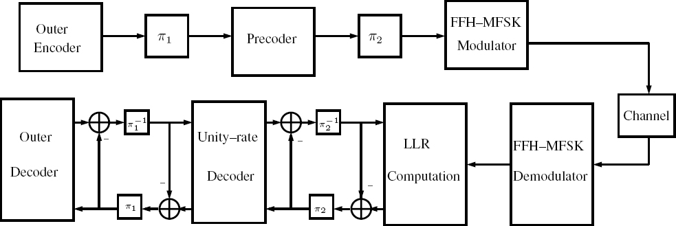
Figure 11.1: Schematic of the IrVLC- and VLC-based schemes employed in conjunction with FFH-MFSK. In the IrVLC coded scheme N = 16, whilst N = 1 in the VLC-coded scheme. ©IEEE [198] Ahmed et al. 2009.

3. By employing EXIT charts, we investigate the serial concatenation of the FFH-MFSK demodulator, unity-rate decoder and IrVLC outer decoder in order to attain a good performance even at low SNR values.
4. We contrast the two-stage ID between the inner rate-1 decoder and the IrVLC outer decoder with the three-stage extrinsic information exchange amongst the demodulator, inner decoder and outer decoder.
The proposed system might find fruitful application in FFH-MFSK-based ad hoc or cellular networks transmitting, for example, VLC-compressed H.264/MPEG-4 video or audio signals. The VLC compression may also provide useful data rate and bandwidth efficiency gains in pure data transmission by exploiting the potential latent correlation of bits.
The rest of this chapter is structured as follows. In Section 11.2 the system considered is described, and the concept of joint source and channel coding is elaborated. In Section 11.3 the soft metrics are derived, and the ID process is discussed with emphasis on the EXIT characteristics of the precoder and the demodulator. In Section 11.4 the choice of IrVLC code parameters is discussed with the aid of EXIT charts, and our Bit-Error Ratio (BER) results are discussed. Finally, in Section 11.5, we present our conclusions.
11.2 System Overview
In this section we consider two serially concatenated and iteratively decoded joint source and channel coding schemes. Specifically, we consider an IrVLC codec and an equivalent regular VLC-based benchmark in this role. We refer to these schemes as the IrVLC and the VLC-FFH-MFSK arrangements, respectively. The schematic that is common to both of these schemes is shown in Figure 11.1.
11.2.1 Joint Source and Channel Coding
The schemes considered are designed for facilitating the low-BER transmission of source symbol values over an uncorrelated Rayleigh fading channel. We consider K = 16-ary source symbol values that have the probabilities of occurrence that result from the Lloyd–Max quantization [164] of independent Laplacian distributed source samples. More explicitly, we consider the four-bit Lloyd–Max quantization of a Gaussian source. Note that these occurrence probabilities vary by more than an order of magnitude, between 0.0023 and 0.1616. These probabilities correspond to entropy or average information values between 2.63 bits and 8.74 bits, motivating the application of VLC and giving an overall source entropy of E = 3.47 bits/VLC symbol.
In the transmitter of Figure 11.1, the source symbol frame s to be transmitted is partitioned into J four-bit source symbols corresponding to K = 16-ary values of ![]() These four-bit source symbols are then decomposed into N component streams
These four-bit source symbols are then decomposed into N component streams ![]() to be protected by the N different-rate IrVLC component codes, where we opted for N = 16 in the case of the IrVLC-FFH-MFSK scheme and N = 1 in the case of the VLC-based benchmark scheme. The number of symbols in the source symbol frame s that are decomposed into the source symbol frame component sn is specified as Jn, where we have J1 = J in the case of the VLC-based scheme. By contrast, in the case of the IrVLC-based scheme, the specific values of
to be protected by the N different-rate IrVLC component codes, where we opted for N = 16 in the case of the IrVLC-FFH-MFSK scheme and N = 1 in the case of the VLC-based benchmark scheme. The number of symbols in the source symbol frame s that are decomposed into the source symbol frame component sn is specified as Jn, where we have J1 = J in the case of the VLC-based scheme. By contrast, in the case of the IrVLC-based scheme, the specific values of ![]() may be chosen in order to shape the inverted EXIT curve of the IrVLC codec so that it does not cross the EXIT curve of the precoder, as will be detailed in Section 11.4.
may be chosen in order to shape the inverted EXIT curve of the IrVLC codec so that it does not cross the EXIT curve of the precoder, as will be detailed in Section 11.4.
Each of the N source symbol frame components ![]() is VLC-encoded using the corresponding codebook from the set of N VLC codebooks
is VLC-encoded using the corresponding codebook from the set of N VLC codebooks ![]() having a range of coding rates
having a range of coding rates ![]() satisfying
satisfying

where αn = Jn/J is the particular fraction of the source symbol frame coded by the nth sub-code and R is the average code rate of the VLC or the IrVLC scheme. The specific source symbols having the value of k ∈ [1 ...K] and encoded by the specific VLC codebook VLCn are represented by the codeword VLCn, k, which has a length of In, k bits. The Jn VLC codewords that represent the Jn source symbols in the source symbol frame component sn are concatenated to provide the transmission frame component ![]()
Owing to the variable length of the VLC codewords, the number of bits comprised by each transmission frame component un will typically vary from frame to frame. In order to facilitate the VLC decoding of each transmission frame component un, it is necessary to explicitly convey the exact number of bits ![]() to the receiver with the aid of side information. Furthermore, this highly error-sensitive side information must be reliably protected against transmission errors. This may be achieved using a low-rate block code or repetition code, for example. For the sake of avoiding obfuscating details, this is not shown in Figure 11.1.
to the receiver with the aid of side information. Furthermore, this highly error-sensitive side information must be reliably protected against transmission errors. This may be achieved using a low-rate block code or repetition code, for example. For the sake of avoiding obfuscating details, this is not shown in Figure 11.1.
11.2.2 FFH-MFSK Modulation
The N transmission frame components ![]() encoded by the different IrVLC component codes are concatenated at the transmitter, as shown in Figure 11.1. The resultant transmission frame u has a length of
encoded by the different IrVLC component codes are concatenated at the transmitter, as shown in Figure 11.1. The resultant transmission frame u has a length of ![]() bits. Following the bit interleaver π, the binary transmission frame u is precoded and the precoded bits are converted to M-ary symbols [347], which are transmitted by the FFH-MFSK modulator of Figure 11.1. To elaborate, in the FFH-MFSK transmitter the M-ary symbols are mapped to M frequency tones [352]. The particular MFSK tone chosen for transmission modulates a carrier generated by a frequency synthesizer, which is controlled by the L-tuple FFH sequence generated by a Pseudo-Noise (PN) generator, where L is the number of frequency hops per symbol. Hence, the transmitted FFH signal hops from one frequency to another in a pseudorandom fashion over a wide bandwidth. The signal transmitted during the ith symbol duration of Ts may be expressed as
bits. Following the bit interleaver π, the binary transmission frame u is precoded and the precoded bits are converted to M-ary symbols [347], which are transmitted by the FFH-MFSK modulator of Figure 11.1. To elaborate, in the FFH-MFSK transmitter the M-ary symbols are mapped to M frequency tones [352]. The particular MFSK tone chosen for transmission modulates a carrier generated by a frequency synthesizer, which is controlled by the L-tuple FFH sequence generated by a Pseudo-Noise (PN) generator, where L is the number of frequency hops per symbol. Hence, the transmitted FFH signal hops from one frequency to another in a pseudorandom fashion over a wide bandwidth. The signal transmitted during the ith symbol duration of Ts may be expressed as

where P is the power of the transmitted signal; PTh(t) denotes a rectangular signaling waveform associated with one hop duration of Th = Ts/L; fm, m = 0, 1, ..., M − 1 is the MFSK tone’s frequency and fl is the lth frequency, l = 0, 1, ..., L − 1, in the frequency hopping sequence during the time interval lTh ≤ t < (l + 1)Th. Furthermore, in Equation (11.2), ϕ represents the cumulative phase induced by the FFH-MFSK modulation.
11.2.3 The Channel
The channel is assumed to be a frequency-flat Rayleigh fading medium for each of the transmitted frequencies. Furthermore, we assume that the separation between the adjacent frequencies is higher than the coherence bandwidth of the channel. The separation between adjacent frequency tones is assumed to be Rh = 1/Th, which also represents the bandwidth occupied by a single FFH-MFSK tone. Therefore, all FFH tones conveying the same symbol experience independent fading.
The transmitted signal is also corrupted by Additive White Gaussian Noise (AWGN) and a PBNJ signal [341, 352], having single-sided power spectral densities of N0 and NJ respectively. We assume that the PBNJ signal jams a fraction 0 ≤ ρ ≤ 1of the total spread spectrum bandwidth Wss. We also assume that the PBNJ signal is contiguous and hence that all the M FSK tones of a particular band are jammed if the jamming signal is present in that band. Thus, the probability that a band or a tone is jammed is given by ρ, while the probability that the band is not jammed is (1− ρ).
11.2.4 FFH-MFSK Demodulation
The receiver schematic is also shown in Figure 11.1, where the frequency de-hopper, which is identical to and aligned with the frequency hopper of the transmitter, de-spreads the received signal by exploiting the knowledge of the transmitter’s unique FFH address. The demodulator of Figure 11.1 consists of M branches, each corresponding to a single MFSK tone and consisting of a square-law detector [352] as well as a diversity combiner, which performs clipping followed by linear combining of the signals received in all hops. The process of clipping is expressed by [338, 353]
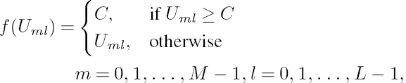
where Uml represents the square-law detector’s output seen in Figure 11.1, corresponding to the mth tone in the lth hop, and C represents an appropriately chosen clipping threshold. The decision variable recorded after clipped combining is given by

At the output of the diversity combiner, the corresponding symbol probabilities and Logarithmic Likelihood Ratios (LLRs) are computed, as explained in the following section, and these are then fed to the unity-rate decoder of Figure 11.1.
11.3 Iterative Decoding
In this section we discuss how soft information is derived from the channel’s output observations and how ID is carried out by exchanging extrinsic information between the demodulator, the unity-rate decoder and the outer decoder seen in Figure 11.1.
11.3.1 Derivation of Soft Information
The LLR output by the demodulator corresponding to the ith bit bi (given that Z = [Z0, Z1, ..., ZM − 1], which represents the set of M diversity combiner outputs of Figure 11.1 is received) may be expressed as [354]

where P(·) denotes the probability of an event, the superscript M indicates the MFSK-based demodulator, and the subscript p denotes a posteriori probability. In order to compute the LLRs, we need the probability that the mth symbol sm was transmitted, m = 0, ..., M − 1, given that the signal Z, which represents the set of M outputs of the diversity combiners of Figure 11.1, is received. This probability is given by

where p(Z|sm) is the Probability Density Function (PDF) of the received signal Z, given that sm is transmitted. Furthermore, P(sm) is the a priori probability of the symbol sm, while ![]() is the probability of receiving the signal set Z, which is independent of sm, m = 0, ..., M − 1, for agiven Z. Moreover, for equiprobable symbols, we have P(sm) = 1/M. Hence, the PDF p(Z|sm) uniquely and unambiguously describes the statistics required for estimating the probability P(sm|Z). For independent fading of the M tones, the PDF p(Z|sm) is given by
is the probability of receiving the signal set Z, which is independent of sm, m = 0, ..., M − 1, for agiven Z. Moreover, for equiprobable symbols, we have P(sm) = 1/M. Hence, the PDF p(Z|sm) uniquely and unambiguously describes the statistics required for estimating the probability P(sm|Z). For independent fading of the M tones, the PDF p(Z|sm) is given by
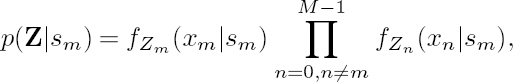
where fZn(xn|sm) represents the PDF of the nth diversity combiner output, n = 0, 1, ..., M − 1, given that sm is transmitted.
In order to derive the PDFs of the diversity combiner outputs, we first consider the PDFs of the square-law detector outputs before diversity combining, as seen in Figure 11.1. We derive the soft information from the channel’s output observations assuming a somewhat simplistic but tractable interference-free channel model. This is because we aim to derive an expression for the soft information that may be computed using the parameters that may be either known or readily estimated at the receiver. By contrast, if the soft information is derived by considering the presence of PBNJ, the desired expression will be a function of parameters such as the signal-to-jammer ratio and the PBNJ duty factor ρ, which are not known at the receiver. Moreover, although clipped combining is employed in the receiver, we perform the forthcoming analysis assuming linear combining, using no clipping at the receiver. This assumption has been stipulated in order to further simplify the analysis, and is supported by the observation that clipping is an operation performed to reduce effects of PBNJ [338]. Hence our analysis may result in suboptimal soft information, but we nevertheless demonstrate in Section 11.4 that valuable performance improvements can be achieved using this approach.
Assuming that sm is transmitted in the lth hop, it can be readily shown that for independent Rayleigh fading the PDF of the noise-normalized square-law detector output Uml, seen in Figure 11.1, may be expressed as [352]
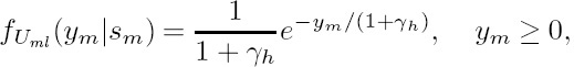
where γh = bREb/(N0L) is the SNR per hop, Eb is the transmitted energy per bit and b = log2M is the number of bits per symbol.
Similarly, for all the interfering or non-signal tones associated with n = 0, 1, ..., M − 1, n ≠ m, the corresponding PDF is given by
From Equation (11.8), using the Characteristic Function approach [352]3, we can derive the PDF of the linear combiner’s output Zm seen in Figure 11.1, which can be expressed as
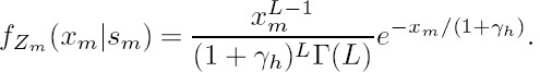
Similarly, for all the non-signal tones, n = 0, 1, ..., M − 1, n ≠ m we have

Inserting Equations (11.10) and (11.11) in Equation (11.7) and after further simplifications, we have

We can see in Equation (11.12) that all the terms except the last exponential term are common for any of the m symbols, m = 0, 1, ..., M − 1. Since the computation of the LLRs requires the logarithm of the bit probabilities, we consider the common terms as a normalization factor and express the normalized probability p(Z|sm) as
Upon inserting Equation (11.13) in Equation (11.6), we can derive the corresponding symbol probabilities. The resultant bit probabilities can be derived from the symbol probabilities, assuming the bits-to-symbol mapping of [347] using the relation of [344, 347]

where ![]() represents the largest integer less than or equal to x. Finally, the LLRs ΛMp are computed from the bit probabilities using Equation (11.5) and after subtracting the a priori LLRs, the extrinsic LLRs may be fed to the decoder.
represents the largest integer less than or equal to x. Finally, the LLRs ΛMp are computed from the bit probabilities using Equation (11.5) and after subtracting the a priori LLRs, the extrinsic LLRs may be fed to the decoder.
In the foregoing analysis, we noted that the knowledge of the received SNR is required to compute symbol probabilities from Equation (11.13). In noncoherent systems, especially in FFH-MFSK, accurate estimation of the channel during a hop interval that is typically a fraction of the symbol interval may not be practicable. However, the SNR may be estimated to a reasonable degree of accuracy by computing a running average of the received AWGN power over a sufficiently large number, say 20, of received samples. We assume in this contribution that the received SNR is accurately known at the receiver.
11.3.2 Two-Stage and Three-Stage Concatenated Schemes
Following our derivation of the soft information from the received signal, two types of serial concatenation schemes are possible. In the first case, depicted in Figure 11.1, the A Posteriori Probability (APP) SISO unity-rate decoder and the outer decoder perform ID, both invoking the Bahl–Cocke–Jelinek–Raviv (BCJR) algorithm [48] using bit-based trellises [180]. The extrinsic soft information is iteratively exchanged between the rate-1 decoder and the VLC decoding stages in the form of LLRs for the sake of assisting each other’s operation, as detailed in [275]. We refer to this configuration of the ID as the two-stage scheme. Alternatively, the system may be modified so that the FFH-MFSK demodulator, the unity-rate inner decoder and the IrVLC outer decoder exchange their extrinsic Mutual Information (MI), as shown in Figure 11.2. We refer to this arrangement as the three-stage scheme. The three-stage scheme requires an additional interleaver between the precoder and the FFH-MFSK modulator of Figure 11.2.
Figure 11.2: Schematic of the system of Figure 11.1, modified for a three-stage serial concatenation of the demodulator, unity-rate decoder and outer VLC/IrVLC decoder. The FFH-MFSK modulator and demodulator and the outer encoder and decoder are as shown in Figure 11.1. ©IEEE [198] Ahmed et al. 2009.
11.3.3 EXIT-Chart Analysis
Let us now study the MI characteristics of the FFH-MFSK demodulator using EXIT curves [346]. All MI measurements were made using the histogram-method-based approximation of the true distribution [346]. Note that in Figure 11.1, Λ(·) denotes the LLRs of the bits concerned, where the superscript i indicates the inner decoder (or demodulator), while o corresponds to outer decoding. Additionally, a subscript denotes the dedicated role of the LLRs, with a, p and e indicating a priori, a posteriori and extrinsic information, respectively. Moreover, unless otherwise stated, we employ the following parameter values: source symbol frame length of J = 70 000, code rate of 0.5, MFSK modulation order of M = 16 and FFH diversity order of L = 3. Finally, we assume optimum clipping thresholds, defined in Equation (11.3), for all simulations.
In Figure 11.3, the MI transfer characteristics of the FFH-MFSK demodulator recorded in a Rayleigh fading channel are shown for various M values, assuming L = 3 and Eb/N0 = 8 dB. In order to portray these EXIT curves in the correct perspective, the inverted EXIT curve of a half-rate Recursive Systematic Convolutional (RSC) decoder characterized by the octal generator polynomial of (7, 5) is also shown. Figure 11.3 demonstrates that the FFHMFSK demodulator yields low-gradient EXIT curves for all values of the modulation order M shown. When the SNR is sufficiently high, the EXIT curves can be shifted upward in the EXIT plane, and hence an arbitrarily low BER may be achieved. However, this would be achieved at the cost of having a large area between the demodulator’s and the RSC decoder’s EXIT curves, implying that the scheme operates far from capacity.
In order to generate an inner decoder EXIT curve that is more conducive to fruitful extrinsic information exchange with the outer IrVLC decoder, we employ a precoder, characterized by the generator polynomial of 1/(1 + D) [350], between the IrVLC encoder and the FFH-MFSK modulator, as shown in Figure 11.1. The MI transfer characteristics of the unity-rate decoder recorded for various values of precoder memory are shown in Figure 11.4. It can be seen that the precoder renders the channel to appear recursive [350], and hence has steeper EXIT curves than does the stand-alone demodulator. Furthermore, as the precoder’s memory is increased, the EXIT curves become steeper. Moreover, in contrast with those of the demodulator, the rate-1 decoder’s EXIT curves do indeed reach the (IE, IA) = (1, 1) point in Figure 11.4, implying that the precoder allows the iterative decoding to converge to an arbitrarily low BER. In our subsequent analysis, we opt for a memory-3 precoder.
Figure 11.3: EXIT characteristics of FFH-MFSK demodulator in interference-free Rayleigh fading channel, assuming Eb/N0 = 8dB and various M values.

Let us now employ the EXIT-chart technique in order to investigate the three-stage MI information exchange amongst all the three components of the receiver; namely, the FFHMFSK demodulator, the inner unity-rate decoder and the outer IrVLC decoder. Ideally, this would require a 3D EXIT chart depicting the evolution of the MI at the output of all the three serially concatenated components. However, a simpler and almost equally effective method of investigating this three-way MI exchange was proposed in [355], which implies treating the FFH-MFSK demodulator and the unity-rate inner decoder as a single module. This effectively allows us to analyze the three-stage concatenation as a two-stage one using 2D EXIT charts. We will refer to this module as the combined module. The EXIT characteristics of the combined module are depicted in Figure 11.5 for various values of the precoder memory at Eb/N0 = 4.8 dB. We note that the combined module yields an EXIT curve similar to that of the unity-rate decoder seen in Figure 11.4, although at a much lower SNR value. This indicates that our three-stage concatenated scheme may yield arbitrarily low BERs at even lower SNR values. We also observe in Figure 11.5 that both precoder memory 1 and memory 2 yield equally attractive EXIT gradients, while a precoder memory higher than 2 results in an EXIT curve that starts at a very low IE value on the y axis and consequently is unsuitable for accurate matching with the outer IrVLC decoder. Thus, for the three-stage scheme, we employ a precoder of memory 1.
Figure 11.4: EXIT characteristics of the rate-1 decoder in interference-free Rayleigh fading channel, assuming Eb/N0 = 6.5dB and various values of the precoder memory. ©IEEE [198] Ahmed et al. 2009.

Figure 11.5: EXIT characteristics of the combined module in interference-free Rayleigh fading channel, assuming Eb/N0 = 4.8dB and various values of the precoder memory.

Figure 11.6: EXIT characteristics of the demodulator, the rate-1 decoder and the combined module in Rayleigh fading channel contaminated by PBNJ, assuming Eb/N0 = 6 dB, Eb/N J = 10dB and ρ = 0.1.

In Figure 11.6 we further compare the EXIT characteristics of the three types of inner modules considered, namely the stand-alone FFH-MFSK demodulator, the stand-alone rate1 decoder and the combined module of demodulator plus the rate-1 decoder, in a channel contaminated by PBNJ. In this figure, we have assumed Eb/N0 = 6dB, Eb/N J = 10dB and a jamming duty factor of ρ = 0.1. We observe that the combined module retains its superiority in this type of channel as well, and, although its EXIT curve has a similar gradient to that of the rate-1 decoder, its EXIT curve emerges from a higher point in the EXIT plane, indicating that the combined module would allow satisfactory communication at lower SNR values. The superiority of the combined module over the stand-alone rate-1 decoder stems from the fact that when employing the combined module extrinsic information is exchanged between the two SISO modules, i.e. the demodulator and the rate-1 decoder, thus enabling optimum exploitation of the soft information.
Note that our combined module invokes a single iteration of extrinsic information exchange between the demodulator and the unity-rate decoder. We have also investigated the use of more than one iteration between these two blocks, but it was found that no additional benefit is achieved. Hence, when the three-stage scheme of Figure 11.2 is employed, each ID iteration involves one iteration between the demodulator and the unity-rate decoder followed by one iteration between the unity-rate inner decoder and the outer decoder.
11.3.4 VLC Decoding
Since N separate VLC encoders are employed in the IrVLC-FFH-MFSK transmitter, N separate VLC decoders are employed in the corresponding receiver seen in Figure 11.1. In parallel with the composition of the bit-based transmission frame u from N VLC components, the a priori LLRs Λao(u) are decomposed into N components, as shown in Figure 11.1. This is achieved with the aid of the explicit side information that we assume for conveying the number of bits In in each transmission frame component un. Each of the N VLC decoders is provided with the a priori LLR sub-frame Λa(un) and in response it generates the a posteriori LLR sub-frame Λp(un), n ∈ [1...N]. These a posteriori LLR sub-frames are concatenated in order to provide the a posteriori LLR frame Λp(u), as shown in Figure 11.1.
During the final decoding iteration, N bit-based MAP VLC sequence estimation processes are invoked instead of single-class APP SISO VLC decoding, as shown in Figure 11.1. In this case, each transmission frame component un is estimated from the corresponding a priori LLR frame component Λao(un). The resultant transmission frame component estimates ![]() n of Figure 11.1 may be concatenated to provide the transmission frame estimate
n of Figure 11.1 may be concatenated to provide the transmission frame estimate ![]() . Additionally, the transmission frame component estimates
. Additionally, the transmission frame component estimates ![]() n may be VLC decoded to provide the source symbol frame component estimates
n may be VLC decoded to provide the source symbol frame component estimates ![]() n. Since this process cannot exploit the knowledge that the source symbol frame component sn comprises Jn source symbols, the resultant source symbol frame component estimate
n. Since this process cannot exploit the knowledge that the source symbol frame component sn comprises Jn source symbols, the resultant source symbol frame component estimate ![]() n may not contain jn source symbols. For the sake of preventing the resultant loss of synchronization that this would imply, source symbol estimates are appropriately removed from, or appended to the end of, each source symbol component estimate
n may not contain jn source symbols. For the sake of preventing the resultant loss of synchronization that this would imply, source symbol estimates are appropriately removed from, or appended to the end of, each source symbol component estimate ![]() n, so that they each comprise the required Jn number of source symbol estimates. These adjusted source symbol component estimates
n, so that they each comprise the required Jn number of source symbol estimates. These adjusted source symbol component estimates ![]() n may be concatenated to generate the source symbol frame estimate
n may be concatenated to generate the source symbol frame estimate ![]() , as shown in Figure 11.1.
, as shown in Figure 11.1.
In the next section we detail the design of our IrVLC scheme and characterize the IrVLCand VLC-based schemes with the aid of EXIT-chart analysis.
11.4 System Parameter Design and Results
As described in Section 11.2, we opted for employing N = 16component VLC codebooks {VLCn}N having approximately equally spaced coding rates in the range of [0.2, 0.95] in the IrVLC-FFH-MFSK schemes of Figure 11.1 and 11.2. In each case, we employ a Variable-Length Error-Correcting (VLEC) codebook [179] that is tailored to the source symbol values’ probabilities of occurrence described in Section 11.2. By contrast, in the VLC scheme we employ just N = 1VLC codebook, which is identical to the VLC codebook VLC10 of the IrVLC scheme, having a coding rate of R = 0.5. Note that this coding rate results in an average interleaver length of J · E/R bits.
In Figure 11.7 we provide the inverted EXIT curves that characterize the bit-based APP SISO VLC decoding of the above-mentioned VLC codebooks, together with the rate-1 decoder’s EXIT curves at Eb/N0 values of 6.6 and 6.9 dB, assuming an uncorrelated Rayleigh fading channel contaminated by PBNJ characterized by Eb/NJ = 10dB and ρ = 0.1. All the EXIT curves were generated using uncorrelated Gaussian distributed a priori LLRs, based on the assumption that the transmission frame’s bits have equiprobable logical values. This is justified because we employ a long interleaver length and because the entropy of the VLC encoded bits was found to be only negligibly different from unity for all the VLC codebooks considered.
Figure 11.7 also shows the inverted EXIT curve of the IrVLC scheme. This was obtained as the appropriately weighted superposition of the N = 16 component VLC codebooks’ inverted EXIT curves, where the weight applied to the inverted EXIT curve of the component VLC codebook VLCn is proportional to the specific number of source symbols employed for encoding Jn [149]. Using the approach of [149], the values of {Jn}Nn = 1 given in Figure 11.7 were designed so that the IrVLC coding rate matches that of our regular VLC scheme, namely 0.5. Furthermore, we ensured that the inverted IrVLC EXIT curve did not cross the rate-1 decoder’s EXIT curve at Eb/N0 of 6.6 dB. We note that only four of the 16 VLC components were indeed activated by the algorithm of [149] in order to encode a nonzero number of source symbols. As shown in Figure 11.7, the presence of the resultant open EXIT-chart tunnel implies that an infinitesimally low BER may be achieved by the IrVLC-FFH-MFSK scheme for Eb/N0 values above 6.6 dB. In contrast, an open EXIT-chart tunnel is not afforded for Eb/N0 values below 6.9 dB in the case of the benchmark VLC-based scheme.
Figure 11.7: Inverted VLC EXIT curves and rate-1 decoder EXIT curves, assuming Eb/NJ = 10 dB and ρ = 0.1, in uncorrelated Rayleigh fading channel. ©IEEE [198] Ahmed et al. 2009.
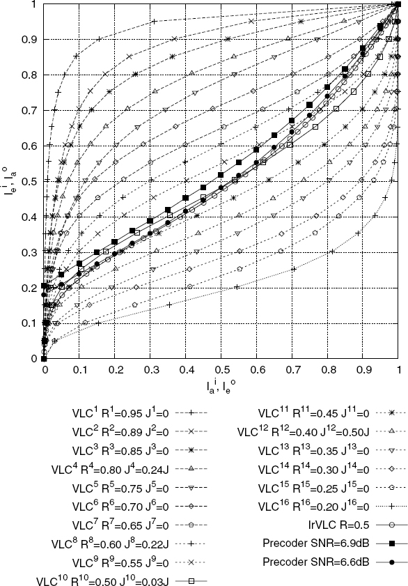
Figure 11.8: EXIT curves of the IrVLC decoder and the combined module, and decoding trajectory, assuming an interference-free, uncorrelated Rayleigh fading channel.

Analogously to the IrVLC design of Figure 11.7, we have also designed IrVLC codes for both the two-stage and the three-stage ID schemes, assuming various jamming scenarios in Rayleigh fading channels. The design parameter values are listed in Table 11.1, where the relevant minimum values of Eb/N0 or Eb/NJ at which an open convergence tunnel is formed are shown alongside the specific fractions of the source symbol frame encoded by each component code of the IrVLC scheme given by αn = Jn/J. For both the IrVLC and the VLC schemes, theoretical as well as the actual values are shown. The theoretical values imply those predicted by the EXIT-chart analysis, while the actual values are those achieved in the Monte Carlo simulations.
The validity of our EXIT-chart analysis was verified by carrying out the ID process of Figure 11.1 and recording the MI values at the output of the inner and outer decoders, as seen in Figure 11.8. We observe that the ID trajectory more or less follows the EXIT curves of the inner and outer IrVLC decoders.
Let us now focus our attention on the BER performance of the proposed system as well as on that of the benchmark in the context of the two-stage and the three-stage schemes considered. Note that the BER depicted in Figures 11.9 to 11.10 corresponds to the encoded bits of the transmission frame u and the corresponding received frame ![]() . The performance predictions of Figure 11.7 are verified for the two-stage scheme by the BER versus Eb/N0 results of Figure 11.9, where we assume Eb/NJ = 10dB and ρ = 0.1when the transmitted signal encounters PBNJ. Also shown is the BER performance of the VLC scheme dispensing with the precoder and thus invoking ID between the demodulator and the VLC decoder. We observe that both the precoded arrangements, namely the VLC-and the IrVLC-based schemes, yield significantly superior performance compared with the system operating without the precoder, attaining a Eb/N0 gain of approximately 7 dB at a BER of 10−4 in the jammed channel. Furthermore, we observe that the IrVLC scheme achieves an arbitrarily low BER at Eb/N0 values in excess of 5.7 dB in interference-free channels and at 6.6 dB in the channels contaminated by PBNJ, as predicted by the EXIT-chart of Figure 11.7. The corresponding Eb/N0 values for the VLC-based scheme are 5.9 and 6.9 dB respectively.
. The performance predictions of Figure 11.7 are verified for the two-stage scheme by the BER versus Eb/N0 results of Figure 11.9, where we assume Eb/NJ = 10dB and ρ = 0.1when the transmitted signal encounters PBNJ. Also shown is the BER performance of the VLC scheme dispensing with the precoder and thus invoking ID between the demodulator and the VLC decoder. We observe that both the precoded arrangements, namely the VLC-and the IrVLC-based schemes, yield significantly superior performance compared with the system operating without the precoder, attaining a Eb/N0 gain of approximately 7 dB at a BER of 10−4 in the jammed channel. Furthermore, we observe that the IrVLC scheme achieves an arbitrarily low BER at Eb/N0 values in excess of 5.7 dB in interference-free channels and at 6.6 dB in the channels contaminated by PBNJ, as predicted by the EXIT-chart of Figure 11.7. The corresponding Eb/N0 values for the VLC-based scheme are 5.9 and 6.9 dB respectively.
Table 11.1: List of parameter values for the IrVLC codes used in the two-stage as well as the three-stage concatenated schemes undervarious channel conditions, with the code rates of the IrVLC’s component codes given by [0.95 0.89 0.85 0.8 0.75 0.7 0.65 0.6 0.55 0.50.45 0.4 0.35 0.3 0.25 0.2]

Figure 11.9: BER versus SNR performance of the two-stage VLC- and IrVLC-based schemes in both jammed and interference-free uncorrelated Rayleigh fading channels. Eb/NJ = 10 dB and ρ = 0.1 are assumed in the jammed channel.
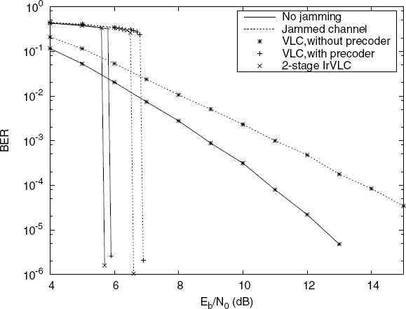
Figure 11.10: BER versus SNR performance of the two-stage and three-stage IrVLC-based schemes in jammed, uncorrelated Rayleigh fading channels for various numbers of decoding iterations, assuming Eb/N J = 10dB and ρ = 0.1. ©IEEE [198] Ahmed et al.2009.

Figure 11.11: BER versus signal-to-jammer ratio performance of the two-stage and threestage VLC- and IrVLC-based schemes in jammed, uncorrelated Rayleigh fading channels, assuming Eb/N0 = 10 dB and ρ = 0.5. ©IEEE [198] Ahmed et al. 2009.

In Figure 11.11 we provide the BER versus Eb/NJ performance comparison of both the two-stage and the three-stage schemes, assuming Eb/N0 = 10dB and ρ = 0.5. We observe that both the VLC-and the IrVLC-based schemes result in superior performance compared with the system operating without the precoder, which encounters an error floor. We also note that the three-stage IrVLC scheme yields a further improvement of nearly 1.1 dB over the two-stage IrVLC. This performance gain confirms the EXIT-chart prediction of Figure 11.6. However, the performance gain achieved by employing three-stage concatenation comes at the cost of an increased complexity, since an additional interleaver is required in the three-stage scheme as shown in Figure 11.2. Moreover, each decoding iteration of the three-stage scheme involves the additional extrinsic information exchange with the demodulator as well.
An increased complexity is also imposed by the increased number of decoding iterations, which is a natural consequence of operating at a lower SNR. This is especially true in the case of the IrVLC scheme, where typically a narrower EXIT tunnel exists between the EXIT curves of the outer and the inner decoders, as seen in Figure 11.7. In Figures 11.9 and 11.11, up to 80 iterations are needed for achieving convergence to (IE, IA) = (1, 1) when employing the IrVLC-based scheme. The effect of reducing the number of iterations on both the two-stage and the three-stage schemes is depicted in Figure 11.10, where the BER versus Eb/N0 performance of the IrVLC schemes considered is shown. We observe that the number of decoding iterations can be significantly reduced by raising the Eb/N0 value by as little as 0.2 to 0.4 dB.
Finally, we observe in Figures 11.9 to 11.10 and Table 11.1 that the actual minimum value of Eb/N0 or Eb/Nj at which convergence is achieved is different from the theoretical prediction when jamming is stronger. Note that under Rayleigh fading the PBNJ becomes more detrimental as its duty factor ρ approaches unity [356, 357]. This also explains the error floor suffered by the system without precoder, as seen in Figure 11.11. Thus, as seen in Table 11.1, when ρ = 0.5is assumed the actual and theoretical convergence threshold values differ by up to 1 dB. The reason for this observation is that the PBNJ induces correlation in the received signal, which cannot be entirely eliminated even by using very large interleaver lengths. Thus, as the jamming gets more detrimental, so does the effect of correlation.
11.5 Conclusion
We have investigated the serial concatenation of IrvLC coding with a FFH-MFSK modem operating in a Rayleigh fading channel, when the transmitted signal was corrupted by PBNJ. Using EXIT-chart analysis, we found that a stand-alone FFH-MFSK demodulator does not promise significant iterative gains, motivating us to employ a unity-rate precoder for the sake of making the channel appear recursive. Furthermore, the IrVLC code was designed in such a way that the inverted EXIT curve of the IrVLC decoder matches the EXIT curve of the inner decoder. In this way, an open EXIT-chart tunnel may be created even at low SNR values, providing source-correlation-dependent additional performance gains of up to 1.1 dB over the VLC-based scheme. Since the employment of the VLC involves non-identical occurrence probabilities for the source symbols, it is not possible to provide a comparison of the proposed scheme with the state of the art in the context of coded FFH-MFSK, which traditionally employs equiprobable source symbols or bits. However, we have provided a comparison of the IrVLC scheme with a VLC scheme dispensing with the precoder; consequently we noted that the precoder-aided schemes yield a Eb/N0 gain in excess of 7 dB over the system dispensing with the precoder, which suffers from an error floor when jamming is severe.
Moreover, we demonstrated that the three-stage concatenation involving the demodulator, the rate-1 decoder and the outer IrVLC decoder yields superior performance compared with the two-stage concatenation of the rate-1 decoder and the outer decoder. However, the three-stage scheme imposes a high complexity owing to the use of an additional interleaver, and because a three-stage decoding iteration entails higher complexity. In contrast, we found that a precoder of memory 1 is more suitable for the three-stage IrVLC scheme, while the two-stage scheme requires a precoder of memory 3, and thus its decoder imposes a higher complexity.
In conclusion, the precoder-aided FFH-MFSK-VLC scheme constitutes a moderate-complexity design option, which can be employed in systems communicating through channels contaminated by PBNJ for transmission of joint source-and channel-encoded audio or video signals. If a higher complexity can be afforded, the IrVLC-based scheme offers additional performance improvements.
1Part of this chapter is based on [337] © IEEE (2009).
2To be recursive in this context implies that the channel has an infinite impulse response.
3The Characteristic Function is the Fourier transform of the PDF, and the fact that the Characteristic Function of a sum of random variables is the product of their individual Characteristic Functions [352] has been exploited here.