
5
Detailed Comparative Analysis and Performance of Fuel Cells
Tejinder Singh Saggu1* and Arvind Dhingra2
1Electrical Engineering Department, Punjab Engineering College, Chandigarh, India
2Electrical Engineering Department, Guru Nanak Dev Engineering College, Ludhiana, India
Abstract
The depleting conventional sources of energy have put strains on the availability of power in the energy-savvy world. Newer sustainable sources of energy need to be harnessed to meet the ever-growing demand for energy. Fuel cells are one such source, which is non-polluting and sustainable. Fuel cells provide a technological idea for a potentially wide variety of future applications in energy storage applications, which could include on-site electric power for our houses and commercial buildings. They are used in different fields of applications like industrial, residential, commercial, and transportation. Their efficiency is very high as compared to ordinary combustion engines and standard batteries with almost zero emissions. During their operation, there is a complete absence of smog because of the lack of various air pollutants. In this chapter, a detailed description and process of various fuel cells along with their field of applications is presented. This comparison is based upon different parameters as per their field of application. This information is essential for the researchers at the beginning level so that they can compare various fuel cells and choose their occupation of the application accordingly.
Keywords: Fuel cells, hydrogen, electrolyte, methanol, alkaline, sustainability
5.1 Introduction
It was Sir Humphrey Davy who gave conceptually the first design of a fuel cell in 1802. Although he could see the potential of it, he was not able to designate the procedure of a carbon fuel cell which would be operational at average room temperature. The electrolyte used in this case was nitric acid. After some time, in 1839, Sir William Grove successfully operated a hydrogen-oxygen fuel cell. In this fuel cell, the chemical reaction was occurring between the oxygen and Hydrogen, and the by-products were water and electricity. This cell re-emphasized the principle of regeneration. Developments continued, and today we have an extensive number of fuel cells that are providing energy for running cars also. Fuel cells have a wide range of applications in several fields. They are beneficial in locations where we do not want pollution because they are a clean source of energy. They are used in military submarines and space planes, among other things. They are in high demand since they are not dependent on fossil fuels, which are rapidly decreasing. Fuel cell technology is designated as the most efficient and clean technology for power generation purposes in a number of applications such as automobile and aircraft systems. This is being done in order to save the environment from a large number of fossil fuels burning. In automobile applications, PEM (polymer electrolyte membrane) fuel cells provide very favorable technology [1, 2]. Another combination of PEM fuel cells along with lithium-ion batteries is also possible in hybrid vehicle technology [3]. The numerous advantages of fuel cells have made them suitable to be used in the field of medical applications as well [4].
The energy storage element in the hybrid system consists mainly of batteries or an ultra-capacitor. The response time of an ultra-capacitor is higher compared to the battery [5]. Some researchers have used several optimization techniques like Genetic algorithms, which will make a hybrid system more efficient and increases its life span as well [6, 7]. To make the system more durable, some researchers have used various modelling tools according to the various components involved in the design process and different operating conditions [8, 9]. Another possibility is to remove organic pollutants like carbohydrates, amino acids and fatty acids from the wastewaters and convert the amount of chemical energy stored in them. For this purpose, a photocatalytic fuel cell can be used [10]. Fuel cells are an efficient technique to supply continuous power to microgrid applications. Fuel cell microgrids can be run independently from the utility power grid using this technology [11, 12].
5.2 Classification of Fuel Cells
The fuel cell works on the principle of converting chemical energy to electrical energy. Usually, hydrogen and oxygen gases are supplied as reactants and electricity, and water are the output available. Hydrogen is used because of the following benefits:
- Hydrogen is the lightest of all gases (Atomic Weight = 1)
- Immense energy content (CV = 143MJ/kg) compared to petrol (CV = 43 MJ/kg), diesel (CV = 45 MJ/kg) and CNG (CV = 52 MJ/kg)
- Low energy density (ρ = 0.019 kg/m3) at STP
- Availability in abundance
- ZERO Emissions
There are several types of fuel cells that differ in their operating temperature, electrolyte, and the fuel used. Here are the most common types of fuel cells:
- Polymer Electrolyte Membrane Fuel Cells (PEMFC): PEMFCs are the most common type of fuel cell, and they use a polymer membrane as an electrolyte. PEMFCs operate at low temperatures, typically between 60-80°C. They are widely used in transportation applications, such as cars, buses, and forklifts, as well as in portable power applications, such as laptops and mobile phones.
- Solid Oxide Fuel Cells (SOFC): SOFCs use a solid ceramic electrolyte and operate at high temperatures, typically between 800-1000°C. They are highly efficient and can use a variety of fuels, such as natural gas, biogas, and hydrogen. SOFCs are commonly used in large-scale power generation applications, such as in combined heat and power (CHP) systems for buildings and in utility-scale power plants.
- Alkaline Fuel Cells (AFC): AFCs use an alkaline electrolyte and operate at high temperatures, typically between 90-100°C. They were first developed for use in space missions, but are now being researched for use in other applications, such as stationary power generation and submarines.
- Phosphoric Acid Fuel Cells (PAFC): PAFCs use phosphoric acid as the electrolyte and operate at higher temperatures than PEMFCs, typically between 150-200°C. They are commonly used in stationary power generation applications, such as in hospitals and office buildings.
- Molten Carbonate Fuel Cells (MCFC): MCFCs use a molten carbonate electrolyte and operate at high temperatures, typically between 600-700°C. They are commonly used in large-scale power generation applications, such as in factories and utility-scale power plants.
Each type of fuel cell has its own advantages and disadvantages, and the choice of fuel cell technology depends on the specific application and requirements. The types of fuel cells and their functioning with applications are discussed in the following sections.
5.2.1 Based on Fuel-Oxidizer Electrolyte
5.2.1.1 Direct Fuel Cell
In this type of fuel cell, fuel and an oxidizing agent are used for the conversion from chemical energy to electrical energy. Fuel cells provide a good solution for processes that demand very high efficiency with low pollution. Some key advantages regarding FCs are:
- Efficiency is more elevated than conventional power plants (30-40%).
- Fuel efficiency can be improved to 90% if waste heat is utilised in the system.
- Low pollution level.
- Low noise level.
- Fuel cell requires low maintenance.
- Cogeneration of heat can increase the efficiency.
Fuel cells (FCs) are categorised in various ways depending on various parameters as discussed above under different operating conditions and temperatures [13]. Direct Fuel Cells (DFCs) are a very economical and emerging type in nature; they have very high energy density and instant recharge capability and they are easily transportable. They have many advantages over Hydrogen Fed Polymer Electrolyte Membrane Fuel Cell (PEMFC). In PEMFC, the fuel used is mainly Hydrogen and it is primarily used in transportation applications [14].
It can be noted that Hydrogen is difficult to transport and can be highly flammable. Also, due to storage problems, DFCs appear to be an excellent alternative to various other fuel cells. Also, because of its easy handling, it is most suitable in the application demanding around 1-3 kW of electrical energy. Furthermore, the devices which operate lithium-ion batteries are difficult to move because of a lack of power supply. Figure 5.1 below shows the functional diagram of DFCs. In DFCs, the oxidation process occurs towards the anode side and liquid fuel is supplied to this side as well. The reduction process happens towards the cathode side, and oxygen gas or air is provided to this side. Hence, electrons pass through an external circuit because charged ions move via the electrolyte. Therefore, the waste product is water towards the cathode, and due to incomplete fuel oxidation, there is some by-product towards the anode side [15]. Due to the high power output of DMFC fuel cells, they are mainly used in various portable equipment [16]. Following are the types of Direct Fuel Cells:
- Methanol-based fuel cells (DMFCs)
- Ethanol-based fuel cells (DEFCs)
- Ethylene glycol–based fuel cells (DEGFCs)
- Glycerol-based fuel cells (DGFCs)
- Formic acid–based fuel cells (DFAFCs)
- Dimethyl ether–based fuel cells (DDEFCs)
- Hydrazine-based acid fuel cells (DHFCs)
Classification based on Temperature
As discussed earlier, the fuel cells are also categorised as per the various operating temperature conditions. For example, SOFC having solid electrolytes basically operates at high temperatures. The detailed review of working temperature, electrolyte, oxidant used and various issues related to fuel cells is tabulated in Table 5.1.
Although a lot of research is going on in the development of an AFC, it is still not favourable to be used as compared to a PEMFC. This is mainly due to some performance instability issues and improper water management within the fuel cell [17]. To make the fuel cell more durable and to improve its performance, fuel recirculation can also be considered. This can be done in two ways: Active and passive fuel recirculation [18].
5.2.1.2 Regenerative FC
A fuel cell that can act in reverse mode is also called a Regenerative Fuel Cell (RFC). It can work in two modes:
- Power Generation Mode
- Reverse Mode
In the first mode, it produces electric energy from the fuel cell, while in the second mode, it generates fuel from electricity [19–21].
Table 5.1 Categorisation of direct fuel cells.
| Parameter | Solid oxide fuel cell (SOFC) | Molten carbonate fuel cell (MCFC) | Phosphoric acid fuel cell (PAFC) | Proton exchange membrane fuel cell (PEMFC) | Alkaline fuel cell (AFC) |
|---|---|---|---|---|---|
| Temperature (oC) | 800-1000 | 600-700 | 160-220 | 80-110 | 60-90 |
| Oxidant | Oxygen or air | Oxygen, CO2 or air | Oxygen or air | Oxygen or air | Oxygen or air |
| Fuel Used | H2/CO/CH4 | H2/CO | H2 reformate | H2 reformate | H2 |
| Electrolyte | ZrO2 with Y2O3 | LiCO3-K2 CO3 | H3PO4 | Polymer membrane | NaOH/ KOH |
| Key issues | Ceramic cells | CO2 recycling necessary | CO sensitivity | Fuel Moisture | CO2 troubles |
| Efficiency (%) | 60-65 | 55-65 | 50-55 | 55-60 | 55-60 |
| Applications | Distributed Generation, Electrical utility, Providing auxiliary power | Distributed Generation, Electrical utility | Distributed Generation | Transportation, Power Backup, Distributed Generation | Transportation, Power Backup, Military, Space |
| Advantages | Fuel flexibility, High efficiency, Suitable for Cogeneration, Solid electrolyte | Fuel flexibility, High efficiency, Suitable for Cogeneration | Suitable for Cogeneration, Enhanced fuel impurities tolerance | Faster start-up, Low temperature, Less electrolytic management problems | Faster start-up, Low temperature, Lower cost components |
| Challenges | Long start-up time, Limited number of shut downs, High temperature corrosion of components | Long start-up time, High temperature corrosion of components, Low power density | Expensive catalysts, Long start-up time, Sulphur sensitivity | Sensitive to fuel impurities, Expensive catalysts | Electrolyte management and conductivity problems, Sensitive to CO2 in fuel and air |

Figure 5.1 Working of regenerative FC in fuel cell mode.
Mode 1: Power Generation Mode (Fuel Cell Mode)
In this mode, as shown in Figure 5.1, energy hydrogen fuel converts electricity using oxygen. Hydrogen, and oxygen is supplied on anode and cathode, respectively. The chemical reaction in this mode is as follows:
 (5.1)
(5.1)Mode 2: Reverse Mode
Energy of DC source and environmental heat is given to RFC in this mode. This allows RFC to decompose water into oxygen and hydrogen fuel. Figure 5.2 shows the basic diagram of this mode. In both modes, two catalysts and Proton Exchange Membrane forms Membrane Exchange Assembly (MEA). After that, Catalysts and MEA start the reaction. The MEA and Catalysts are sandwiched between plates. These plates are called cathode and anode field plates. It has many functions, including distribution of fuel, heat management facilitation, etc.

Figure 5.2 Working of RFC in reverse mode.
 (5.2)
(5.2)5.2.1.3 Indirect Fuel Cells
In the case of direct cells, the hydrocarbon fuel injects straightway into the fuel cell. However, in the case of indirect fuel cells, which are also known as reformed fuel cells, the hydrocarbon fuel is reformed initially to remove the Hydrogen and then it is injected into the fuel cell. The place where the Hydrogen is removed from the hydrocarbons is known as a reformer, which is also known as a separate fuel processing station. On the anode side, the Hydrogen is first broken down into an electron and a proton and further reformed on the cathode side for the production of water, as shown in Figure 5.3 below.
Thus, we can also term indirect fuel cells as the simple hydrogen fuel cells that receive Hydrogen by reforming the hydrocarbons directly on the plant site. Methanol and ethanol are commonly preferred in this process for the production of Hydrogen. Both of these provide better energy having suitable Hydrogen carbon ratio for the same amount of CO2 released.
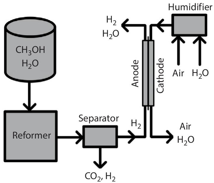
Figure 5.3 Indirect fuel cell operation (Source: iconspng.com).
Advantages:
- There is no cost expenditure for transportation of Hydrogen and thus no risks involved either.
- There are no problems due to catalyst poisoning like indirect fuel cells.
- There is no particular requirement for a water supply and management system as the water is not being supplied with hydrocarbon in the fuel cell.
- Unlike the direct fuel cells, the reforming process is controlled separately in these indirect FCs, hence these types of cells are able to operate at lesser temperatures.
Limitations:
- Indirect fuel cells are challenging to maintain as they are more complex.
- They are not so reliable as direct fuel cells.
- The heat generated by the reformer can be used for some additional applications.
5.2.2 Based on the State of Aggregation of Reactants
5.2.2.1 Solid Fuel Cells
When some complex ceramic compounds like zirconium oxide or calcium oxide are used as electrolytes, the cell is known as a SOFC, as shown in Figure 5.4 below. Such cells operate at around 1000 °C temperature, giving an output of 100 kW with an efficiency of 60-70%. There is no need for a reformer to extract Hydrogen from the fuel at such a high temperature. Thus, electricity can also be produced by recycling the waste heat. Leakage of electrolytes is not possible in these cells like liquid and gaseous fuel cells, but a very high temperature limits the applications of these cells.
In SOFC, the electrolyte used in the cell is of solid oxide material, which conducts negative oxygen ions to the anode from the cathode. On the anode side, the oxidation of carbon monoxide or Hydrogen takes place with the oxygen. The SOFC operates at a very high temperature; hence there is no need for any expensive platinum catalyst. So, instead of a membrane or liquid, zirconium oxide is used as a solid-state catalyst mixed with yttrium oxide. The reaction kinetics are also improved by the application of high temperature having no need for a metal catalyst.

Figure 5.4 SOFC (Source: Fuel cell Store).
SOFCs are classified into mainly three geometries; micro-tubular, planar and coplanar. The air flows inside the solid oxide tube sealed on one side and on the other side, and the fuel flows outside in the tubular design. The cell consists of different layers, and the cathode is represented by the tube itself. Whereas the planar design consists of different flat stacks in which the Hydrogen and air flow through different channels representing cathode and anode. This type of SOFC is mainly used in small and large power plants and cogeneration plants for the production of heat and electricity.
5.2.2.2 Gaseous Fuel Cells
A gaseous FC makes use of a Proton Exchange Membrane (PEM) unit, which uses mainly two types of gases as a fuel; Hydrogen and Oxygen. The final reaction using these gases involves heat, water and electricity as by-products. This technique is very much more straightforward in nature than the other forms of power plants like thermal power plants, nuclear power plants, diesel engines, etc. All these processes cause a lot of pollution and produce detrimental by-products. So, in a gaseous fuel cell, the electrolysis process is usually preferred for supplying Hydrogen; the other gas oxygen is readily available in the atmosphere.
A PEM unit consists of mainly four elements: Anode, cathode, electrolyte and catalyst, as shown in Figure 5.5. The negative terminal of the cell is known as the anode. Its primary function is to collect the electrons from the hydrogen molecules which are used in an external circuit. The hydrogen gas is equally dispersed in the catalyst surface using different channels imprinted on this unit. On the other hand, the positive terminal of the cell is called the cathode. It has separate channels branded to dispense the oxygen molecules over the surface of the catalyst. Electrons from the outside surface are conducted back into the catalyst, where the recombination of Hydrogen and oxygen molecules takes place to produce water.

Figure 5.5 A PEM fuel cell (Source: World Fuel Cell Council).
The PEM unit is basically acting as an electrolyte; whose main function is to conduct positively charged ions. The electrons are basically blocked by the membrane. Therefore, for it to remain in a stable state and function properly, a membrane should always be hydrated. However, the reaction of Hydrogen and oxygen takes place using a catalyst consisting of platinum nanoparticles coating facing the PEM unit. The surface of a catalyst is usually rough and absorbent. This is being done in order to expose the maximum surface area of platinum with oxygen and Hydrogen. The hydrogen PEM fuel cells are mainly used in EV applications. A lot of research is going on for commercializing the manufacturing of PEM fuel cell stacks by examining the various types of barriers in this process [22–24]. The various reactions taking place in a PEM unit are as shown below:
5.2.2.3 Liquid Fuel Cells
In fuel cells, there are plenty of good options available to use the liquid as a fuel. The compressed Hydrogen, Methanol, Ethanol & Ammonia are the primary fuels which are used as a liquid in fuel cells. However, a fuel cell is not so efficient when we use pure Hydrogen as a fuel. The hydrogen infrastructure cost is also very high. A number of sources like hydrocarbons, natural gas, sunlight etc., may be used to produce Hydrogen. This is the primary fuel which has been used to launch space shuttles by NASA since 1970. Electricity, heat and water are produced by mixing Hydrogen with oxygen. A lot of research is going on in this area to utilize pure Hydrogen as a fuel from non-conventional energy sources. Hydrogen is also finding various uses in electric vehicles, producing no pollution at all [25]. The main limitation in this type of cell is the high cost of catalyst as well as its loading. Two main types of liquid fuels using Methanol and ethanol are mainly used for commercial applications [26]. Liquid FCs can also be produced through solar power, and the whole process of this conversion is described in this research article [27].
However, Methanol, Ethanol & Ammonia can be used as such in the fuel cells. One such example is shown in Figure 5.6. They can also be processed outside the fuel cell using a reformer. This is being done to enhance the life of the fuel cell catalyst.
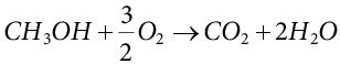
Methanol is an alcohol-based fuel having an energy density higher than compressed Hydrogen. It is also a safer fuel as compared to Hydrogen. It is also readily available from many supply chains. Natural gas, Coal & Biomass are the main sources of producing Methanol across the world. Research shows that fuel cells powered by Methanol are highly preferred for commercial fuel cells. Ethanol as liquid fuel is also an attractive choice because of several advantages like better supply chain, high energy density, lower infrastructure cost, less storage requirements and safer as well. It can be produced from fossil fuels, feedstocks and a variety of biological sources using fermentation and distillation processes. Various plants like corn, sugarcane and switchgrass are also used for its production. Ammonia is also a good option in liquid fuel cells due to its clean combustion properties because only Hydrogen and nitrogen are left as by-products during its reformation process.

Figure 5.6 Liquid fuel cells using Methanol (Source: Fuel Cell Store).
It contains 17.6% of hydrogen atoms, quite similar to the Methanol weight content during partial oxidation reformation, thereby making it an ideal carbon-free fuel [28–30]. By applying a pressure of 10 bar at 300 K using a liquid density of 600 g/L, it is liquefied. The cracking reaction of ammonia is given as:
This high temperature can be obtained using any external source. Ammonia as fuel has one drawback of undissipated ammonia concentration of around 50 ppm during its product gas formation, which may damage the fuel cells. This may be prevented by using an acid scrubber which can quickly ease the traces of ammonia gas from the cracker.
5.2.3 Based on Electrolyte Temperature
5.2.3.1 Proton Exchange Membrane
This cell, also known as polymer electrolyte membrane FC, was discovered in 1959. The operating temperature range for this cell is 50 to 100°C. The cell construction is shown in Figure 5.7 below. The electrocatalyst used is generally platinum, and it is mainly preferred in automobile and submarine applications. The efficiency of this cell is 50 to 60%.
On the anode side, the following chemical reaction takes place:
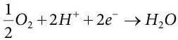
On the cathode side, the following chemical reaction takes place:
 (5.7)
(5.7)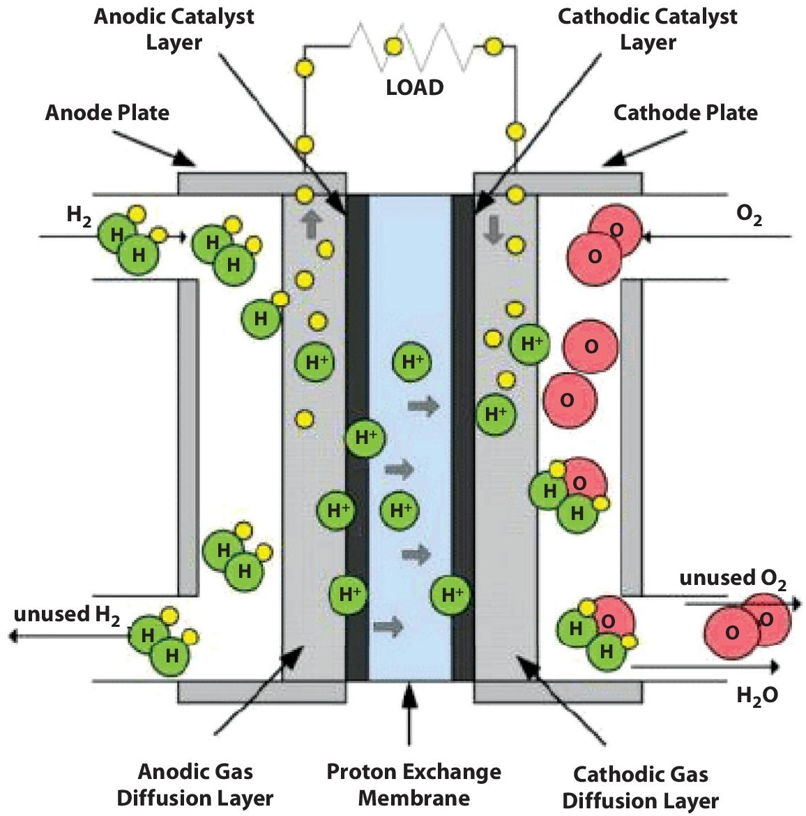
Figure 5.7 Proton exchange membrane fuel cell (Source: researchgate.net).
Thus, net electrochemical reaction is:
 (5.8)
(5.8)The PEM FC is accepted chiefly because it takes significantly less time to start and stop, which makes it suitable to be used in remote areas. Other important parameters of a PEM fuel cell are its durability, sustainability and simplicity, which make it suitable to be used in various industrial areas. It is also widely accepted in the automotive industry and other portable equipment because of its high power density, noise-free operation, lower operating temperature and almost zero carbon emissions.
5.2.3.2 Direct Methanol
This type of cell is shown in Figure 5.8. The development of this fuel cell was done in 1960. The ceramic is being used as an electrocatalyst, and the temperature range of this cell is about 450 to 500°C. The operating efficiency is about 30 to 40%.
On the anode side, the following chemical reaction takes place:
On the cathode side, the following chemical reaction takes place:
 (5.10)
Thus, the net electrochemical reaction is:
 (5.11)
5.2.3.3 Alkaline
This type of cell is shown in Figure 5.9. The development of this fuel cell was also done in 1960. The platinum is being used as an electro catalyst and the temperature range of this cell is about 50 to 220°C. The operating efficiency is about 50 to 60%. It is mainly used in transportation and space shuttle applications.

Figure 5.8 Direct methanol (Source: researchgate.net).

Figure 5.9 Alkaline fuel cell (Source: researchgate.net).
On the anode side, the following chemical reaction takes place:
On the cathode side, the following chemical reaction takes place:
Thus, the net electrochemical reaction is:
5.2.3.4 Phosphoric Acid
This type of cell is shown in Figure 5.10. The development of this fuel cell was done in 1965. Generally, platinum is being used as an electrocatalyst and the temperature range of this cell is about 150 to 220°C. The power density is about 55%. It was the first FC that was used for commercial purposes.

Figure 5.10 Phosphoric acid fuel cell (Source: researchgate.net).
On the anode side, the following chemical reaction takes place:
On the cathode side, the following chemical reaction takes place:
 (5.16)
Thus, the net electrochemical reaction is:
 (5.17)
5.2.3.5 Molten Carbonate
This type of cell is shown in Figure 5.11. The development of this fuel cell was also done in the 1960s. The alkali carbonate is being used as an electrocatalyst, and the temperature range of this cell is about 600 to 700°C. The operating efficiency is about 55 to 65%. It is also used in commercial applications.
On the anode side, the following chemical reaction takes place:
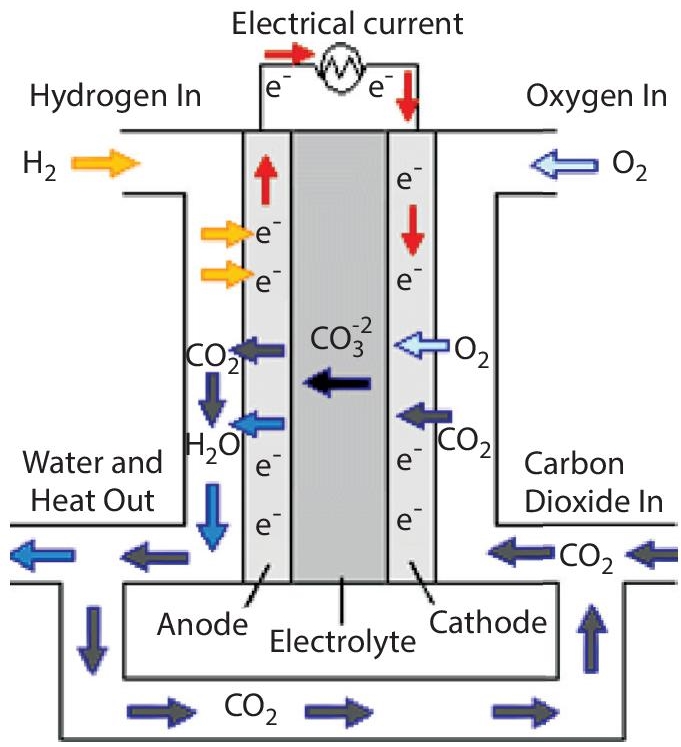
Figure 5.11 Molten carbonate fuel cell (Source: researchgate.net).
On the cathode side, the following chemical reaction takes place:
 (5.19)
Thus, the net electrochemical reaction is:
 (5.20)
5.2.3.6 Solid Oxide
This type of cell is shown in Figure 5.12. The development of this fuel cell was also done in the 1950s. The calcium titanate is being used as an electrocatalyst, and the temperature range of this cell is about 700 to 1000°C. The operating efficiency is about 55 to 65%.
On the anode side, the following chemical reaction takes place:

Figure 5.12 Solid Oxide Fuel cell (Source: researchgate.net).
On the cathode side, the following chemical reaction takes place:
 (5.22)
Thus, the net electrochemical reaction is:
 (5.23)
5.3 Cost of Different Fuel Cell Technologies
A thorough market analysis is essential when determining the best fuel cell for a specific application. This would entail determining the performance and operational needs, such as the number of operating hours, projected life duration, frequency, and so on. For efficient use of fuel cells, a proper system must be designed. This would entail determining how many cells are required, as well as which combinations of stacks are needed. The cost is the next significant consideration. The cost of a fuel cell per kW can vary widely depending on the type of fuel cell, the manufacturing process, the scale of production, and other factors. However, in general, the cost of fuel cells has been decreasing over time as technology advances and production volumes increase. As of 2021, the cost of a proton exchange membrane (PEM) fuel cell, which is one of the most common types of fuel cells used for transportation and stationary power applications, is estimated to be in the range of 395 EUR/kW [31]. However, it is important to note that these estimates can vary widely depending on the specific application and other factors. The detailed comparative analyses of the different fuel cell technologies in term of the cost of the system is found in Refs [31, 32].
5.4 Conclusion
Nowadays, a lot of energy is required in every industry practically, putting a lot of pressure on state electricity boards and utilities to supply this demand. Fuel cells are a prominent source of energy that is both environmentally friendly and sustainable. Their efficiency is relatively high compared to traditional energy sources and conventional batteries, and they emit nearly no carbon dioxide. With the ever-increasing need for electrical energy, the impetus is on to find energy sources that are both sustainable and non-polluting. Thus, fuel cells are ideal for all these applications. This chapter attempts to describe several types of fuel cells, their operating principles, and diverse fields of use such as electric vehicles, hybrid vehicles, medical, commercial, and industrial applications. Researchers interested in working in this discipline can use this information to determine and select their field of application based on their interests.
References
- 1. Yang Luo, Yinghong Wu, Bo Li, Tiande Mo, Yu Li, Shien-Ping Feng, Jingkui Qu, Paul K. Chu, Development and application of fuel cells in the automobile industry. Journal of Energy Storage, 42, 103-124, 2021.
- 2. S. Porstmann, T. Wannemacher, W.-G. Drossel, A comprehensive comparison of state-of-the-art manufacturing methods for fuel cell bipolar plates including anticipated future industry trends. Journal of Manufacturing Processes, 60, 366-383, 2020.
- 3. Mohamed Nacereddine Sid, Mohamed Becherif, Abdenacer Aboubou, Amel Benmouna, Power control techniques for fuel cell hybrid electric vehicles: A comparative study. Computers & Electrical Engineering, 2021.
- 4. Qian Xu, Feihu Zhang, Li Xu, Puiki Leung, Chunzhen Yang, Huaming Li, The applications and prospect of fuel cells in medical field: A review. Renewable and Sustainable Energy Reviews, 67, 574-580, 2017.
- 5. K. Latha, B. Umamaheswari, K. Chaitanya, N. Rajalakshmi, K.S. Dhathathreyan, A novel reconfigurable hybrid system for fuel cell system. International Journal of Hydrogen Energy, 40, 14963-14977, 2015.
- 6. N. Sulaiman, M.A. Hannan, A. Mohamed, P.J. Ker, E.H. Majlan, W.R. Wan Daud, Optimization of energy management system for fuel-cell hybrid electric vehicles: Issues and recommendations. Applied Energy, 228, 2061-2079, 2018.
- 7. Xueqin Lü, Yinbo Wu, Jie Lian, Yangyang Zhang, Chao Chen, Peisong Wang, Lingzheng Meng, Energy management of hybrid electric vehicles: A review of energy optimization of fuel cell hybrid power system based on genetic algorithm. Energy Conversion and Management, 205, 112-124, 2020.
- 8. L. Vichard, N. Yousfi Steiner, N. Zerhouni, D. Hissel, Hybrid fuel cell system degradation modeling methods: A comprehensive review. Journal of Power Sources, 506, 230-245, 2021.
- 9. Julia Savioli, Graeme W. Watson, Computational modelling of solid oxide fuel cells. Current Opinion in Electrochemistry, 21, 14-21, 2020.
- 10. Yasser Vasseghian, Alireza Khataee, Elena-Niculina Dragoi, Masoud Moradi, Samaneh Nabavifard, Gea Oliveri Conti, Amin Mousavi Khaneghah, Pollutants degradation and power generation by photocatalytic fuel cells: A comprehensive review. Arabian Journal of Chemistry, 13, 8458-8480, 2020.
- 11. Subhashree Choudhury, Nikhil Khandelwal, A critical survey of fuel cells applications to microgrid integration: Configurations, issues, potential solutions and opportunities. International Transactions on Electrical Energy System, 213, 1353-1370, 2019.
- 12. Valverde L, F. Rosa, C. Bordons, J. Guerra, Energy Management Strategies in hydrogen Smart-Grids: A laboratory experience. International Journal of Hydrogen Energy, 41, 13715-13725, 2016.
- 13. B.C. Ong a, S.K. Kamarudin, S. Basri, Direct liquid fuel cells: A review. International Journal of Hydrogen Energy, 42, 322-338, 2017.
- 14. Yun Wang, Daniela Fernanda Ruiz Diaz, Ken S. Chen, Zhe Wang, Xavier Cordobes Adroher, Materials, technological status, and fundamentals of PEM fuel cells – A review, Materials Today, 32, 178-203, 2020.
- 15. PJM van Tonder, “Bipolar Plates and Flow Field Topologies for the Regenerative Fuel Cell”, IEEE Africon 2011 - The Falls Resort and Conference Centre, 2011.
- 16. M.S. Alias, S.K. Kamarudin, A.M. Zainoodin, M.S. Masdar, Active direct methanol fuel cell: An overview, International Journal of Hydrogen Energy, 45, 19620-19641, 2020.
- 17. Rambabu Gutru, Zarina Turtayeva, Feina Xu, Gaël Maranzana, Brigitte Vigolo, Alexandre Desforges, A comprehensive review on water management strategies and developments in anion exchange membrane fuel cells, International Journal of Hydrogen Energy, 45, 19642-19663, 2020.
- 18. Junbo Hou, Min Yang, Junliang Zhang, Active and passive fuel recirculation for solid oxide and proton exchange membrane fuel cells, Renewable Energy, 155, 1355-1371, 2020.
- 19. W. Wiyaratn, “Review on Fuel Cell Technology for Valuable Chemicals and Energy Co-Generation”, Engineering Journal, 14, 1-14, 2010.
- 20. F. Alcaide, P. L. Cabot, and E. J. Brillas, “Fuel cells for chemicals and energy cogeneration” Journal of Power Sources, 153, 47-60, 2006.
- 21. Johansson, T.B., McCormick, K., Neij, L., and Turkenburg, W. C, The Potentials of Renewable energy. Renewable Energy: A Global Review of Technologies, London, 15-47, 2006.
- 22. Youhyun Lee, Min Chul Lee, Young Jin Kim, Barriers and strategies of hydrogen fuel cell power generation based on expert survey in South Korea, International Journal of Hydrogen Energy, 2021.
- 23. Mahmoud Dhimish, Romênia G. Vieira, Ghadeer Badran, Investigating the stability and degradation of hydrogen PEM fuel cell, International Journal of Hydrogen Energy, 46, 37017-37028, 2021.
- 24. A. Kampker, P. Ayvaz, C. Schön, J. Karstedt, R. Förstmann, F. Welker, Challenges towards large-scale fuel cell production: Results of an expert assessment study, International Journal of Hydrogen Energy, 45, 29288-29296, 2020.
- 25. Junye Wang, Hualin Wang, Yi Fan, Techno-Economic Challenges of Fuel Cell Commercialization, Engineering, 4, 352-360, 2018.
- 26. B.C. Ong, S.K. Kamarudin, S. Basri, Direct liquid fuel cells: A review, International Journal of Hydrogen Energy, 42, 10142-10157, 2017.
- 27. Shunichi Fukuzumi, Production of Liquid Solar Fuels and Their Use in Fuel Cells, Joule, 1, 689-738, 2017.
- 28. Yuqi Guo, Zhefei Pan, Liang An, Carbon-free sustainable energy technology: Direct ammonia fuel cells, Journal of Power Sources, 476, 223-245, 2020.
- 29. Ahmed Afif, Nikdalila Radenahmad, Quentin Cheok, Shahriar Shams, Jung H. Kim, Abul K. Azad, Ammonia-fed fuel cells: a comprehensive review, Renewable and Sustainable Energy Reviews, 60, 822-835, 2016.
- 30. Osamah Siddiqui, Ibrahim Dincer, A review and comparative assessment of direct ammonia fuel cells, Thermal Science and Engineering Progress, 5, 568-578, 2018.
- 31. A. Kampker, H. Heimes, M. Kehrer, S. Hagedorn, P. Reims, and O. Kaul, Fuel cell system production cost modeling and analysis. Energy Reports, vol. 9, pp. 248–255, 2023.
- 32. Battelle Memorial Institute, Manufacturing Cost Analysis of 100 and 250 kW Fuel Cell Systems for Primary Power and Combined Heat and Power Applications. U.S. Dep. Energy, no. January, pp. 1–260, 2017.
Note
- *Corresponding author: [email protected]