
Chapter 4
Modeling in 3ds Max: Architectural Model Part II
In this chapter, you will continue working with the interior space from the previous chapter by modeling and adding some furniture—specifically, a couch and chair.
Topics in this chapter include:
- Modeling the couch
- Modeling the chair
Modeling the Couch
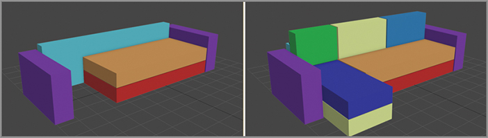
When you are starting a modeling project, make sure you have plenty of measurements, as shown in Figure 4-1’s photo of the couch you’ll model in this chapter. Always remember: reference, reference, reference. Modeling this couch is a very straightforward process. If you break it down into separate components, it is just 16 different sized boxes. The boxes are soft and cushy; they have various details, but nonetheless they are still just boxes. With the exception of the lounge end of the couch, the top cushion is the only piece on the couch that isn’t a box shape.
Figure 4-1: Couch with measurements

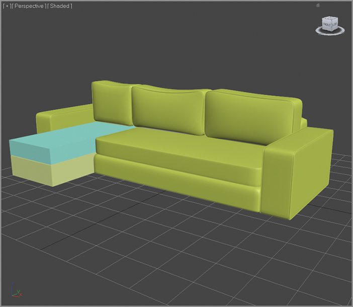
Blocking Out the Couch Model
Blocking out the model means creating a simpler version of the model starting with whatever primitives fit the bill—in this case, boxes. Using the measurements shown in Figure 4-1, you will create a series of boxes and then orient them to mimic the couch. The first piece you’ll create is the bottom (the part between the seat cushions and the feet). Its measurements are 8-inches high by 72-inches wide by 31.5-inches deep. In the previous chapter, you used standard units of measurement (feet and inches); but for this chapter, you will use the default Generic units. If your Units are still set to feet and inches, refer to Chapter 3, “Modeling in 3ds Max: Architectural Model Part I,” under “Units Setup” at the beginning of the chapter, to review how to change it to Generic Units.
Figure 4-2: In the Clone Option dialog box, select Copy and click OK.

Now for the back piece, this is the part the back cushions sit on. We don’t see it in the picture in Figure 4-1, but it is there.
Figure 4-3: The first few pieces to start the couch (left); The blocked-out couch (right)
Creating the chaise part of the couch is a bit more challenging. You’ll create a box now, and later you can alter it with the wing on the side.
This process is getting a bit tedious, but you still need to create the backrest cushions. Refer to Figure 4. 1 for the measurements you’ll need. There should be three backrest cushions (two the same size and one that is smaller). Move them into place on the couch to finish blocking out of the couch, as shown in Figure 4-3. As you are creating the couch pieces, name them. Use descriptive names to help you keep the project organized.
Once you begin adding more detail to the couch pieces, you’ll have to make some adjustments to them by resizing and repositioning them.
Using NURMS to Add Softness
Non-Uniform Rational Mesh Smooth (NURMS) is a subdivision surface technique that allows you to take a low-poly model and smooth the surface into a high-poly model. This isn’t a lighting trick; you are actually changing the geometry of the model. When you apply NURMS to your model, you will see a control cage in the shape of the low-poly model; this is the mesh you actually model. Subdivision increases the poly count of your model; every level of subdivision increases the number of polygons by a factor of four. At a subdivision level (or iteration) of 1, one polygon in the control cage will become four polygons in the subdivided model. At an iteration level of 2, that one polygon becomes 16 polygons, and so on. When you’re working on a model with NURMS, it is best to work with a lower iteration level and then render with a higher level of iterations. Be cautious; poly counts rise very quickly and an iteration count needlessly high can slow you down.
Polygons are flat between the vertices, but when NURMS is turned on, a flat polygon starts to curve and smooth out as it subdivides. When you use NURMS smoothing, the more distance there is between the edges on a mesh, the smoother the result will be. When you want sharp corners, just place the edges close together. When you turning on NURMS, those close edges will retain their sharpness better. If you want a smoother, more rounded surface, then place the edges farther apart.
The best way to model with smooth surfaces is to use quad polygons in a grid formation; two splines will cross each vertex—and because each spline flows from vertex to vertex uninterrupted, the splines will continue and the 3d form will be smoothed predictably. If you have a vertex with more or less than four edges coming out of it, the splines will end and the mesh may not smooth the way you expect it to. If you want to fully understand the concept of splines flowing and ending across a 3D surface as a result of subdivision leads, spend some time studying topology, which is key to creating good 3D models that subdivide well when animated.
Many of the couch cushions will receive the same treatment, so let’s go over the next technique using only the side armrest of the couch and the chaise lounge section. After you’re finished with that, you can practice the techniques on the remaining couch boxes yourself. Continue with the project from the previous exercise or open the Couch_01.max file from the Scenes folder of the Arch Model project from the companion web page.
Figure 4-4: Couch side arm with NURMS applied
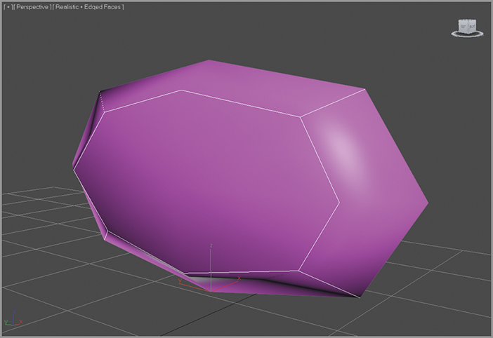
If you refer to the picture of the arm of the couch from Figure 4-1, you’ll see that the arm is much more structured and closer to the shape of a box than this deflated balloon. You still need to sharpen the corners by adding more edges to the base model.
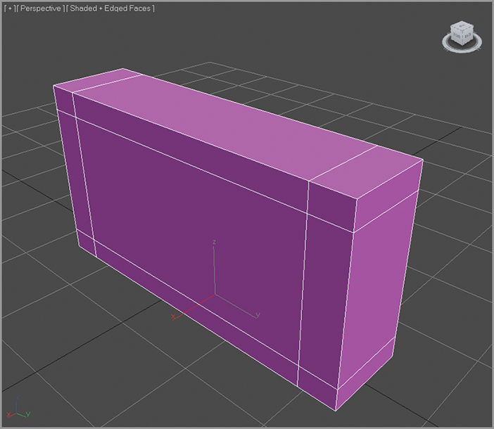
Figure 4-5: Use the SwiftLoop tool to add edge loops to the box.
Adding Details to the Couch
The next step in the process of creating the couch is to add the piping, which is the round decorative trim along the seam of the pillows, as shown in Figure 4-6.
Figure 4-6: Decorative piping runs along the seams of the couch.

Figure 4-7: Select the highlighted edges.

Figure 4-8: Set the Extrusion Type to Local Normal.

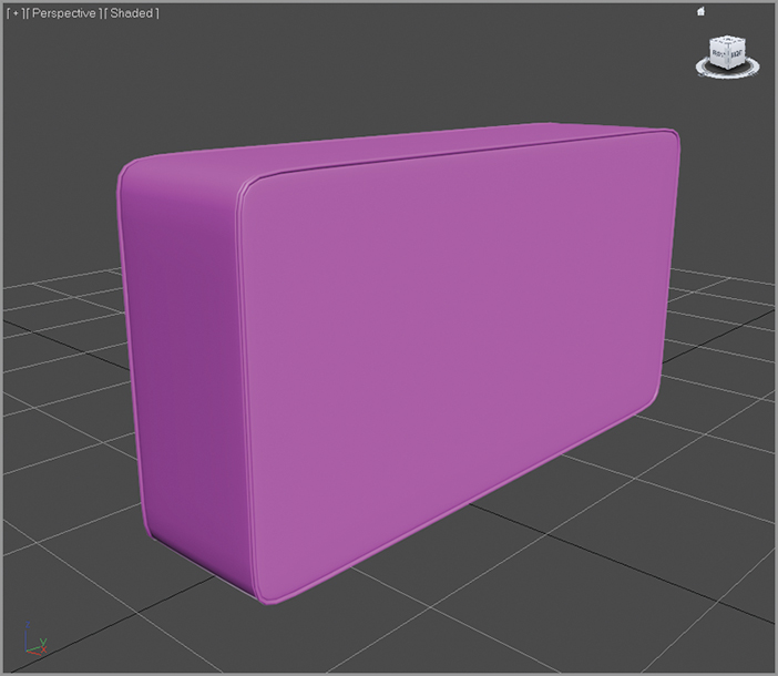
The couch looks pretty good, but if you look closely you can see that it is still very choppy around the corners. The NURMS iterations need to be turned up. When you turn on Use NURMS, a Use NURMS tab appears in the Graphite Modeling Tools ribbon (sometimes a floating window will appear instead). In the Use NURMS tab, turn the Iterations up to 2. The finished product looks pretty good, as shown in Figure 4-9.
Figure 4-9: The finished couch arm
Now it is time to perform the same piping detail on all the remaining couch pieces except the chaise pieces. The seat cushion and three back cushions need to have piping just like the couch arm, so you need to repeat steps 1 through 8 for the cushions. The seat base and couch back don’t have any piping so they just need to be smoothed using NURMS. Make sure to add edge loops at the corners to create the right amount of smoothing and detail. Play around with the settings to match the reference model as much as possible. Finally, you can select vertices and polygons and move them around to give the surfaces a more random and organic or “lived-in” appearance. In Figure 4-10, everything but the chaise lounge part of the couch was finished using NURMS with an iteration level of 2.
Figure 4-10: Finished pieces of the couch
The Chaise Lounge
The chaise lounge isn’t that much different from the rest of the couch. It just has a wing section that comes out from the side, as shown in Figure 4-11. Continue with your own couch file or load Couch_02.max from the Scenes folder of the Arch Model project from the companion web page at www.sybex.com/go/3dsmax2013essentials.
Figure 4-11: The chaise lounge section of the couch

Figure 4-12: Use SwiftLoop to add an edge loop in the area shown in this top view of the chase cushion box.
Now that you have completed the chaise lounge section of the couch, you just have to add the finishing touches. Repeat the same steps you performed to smooth out the meshes using NURMS, add the piping detail at the edges, and move some vertices around to give the cushion a lived-in look.
Creating the Couch Feet
The final pieces you need to create for the couch are the feet. The feet are all the same, so you just need to create one foot and copy it for the other three. In Figure 4-13, look at the feet and note that they are a box shape that is thinner on the bottom. Continue with your own couch file or load the Couch_03.max from the Scenes folder of the Arch Model project from the companion web page.
Figure 4-13: The couch feet with measurements
A modifier changes the geometric structure of a model and a Taper modifier will move the vertices near the end closer together. Using a Taper modifier is an easy way to make simple changes to your model.
Figure 4-14: The Taper parameters

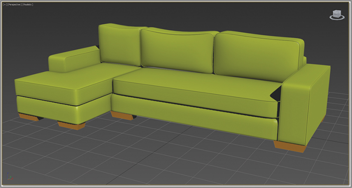
Now that the couch is finished, as shown in Figure 4-15, it should resemble the original couch, but perhaps without the lived-in look and feel the real couch has. You can create some of that look by moving vertices and polygons around so that it does not look quite so perfect.
Figure 4-15: The final couch
Modeling the Chair
To model the chair, you’ll be taking a different approach. You’ll use a spline technique that the 3ds Max software is particularly good at. If you are used to Maya CV curves, the Bezier will seem a bit awkward; but if you are used to Photoshop’s Pen tool, then the 3ds Max Line tools way of making lines should be pretty easy. It isn’t just the way you make the lines that makes the 3ds Max tools so nice; it’s also the tools you use to make the lines into 3D objects.
Figure 4-16 shows the chair that will be modeled in this section. After saving the previous exercise’s file, click on the Applications button and choose Reset from the list that appears. This will set your interface and file back to a startup state. Start a new 3ds Max file.
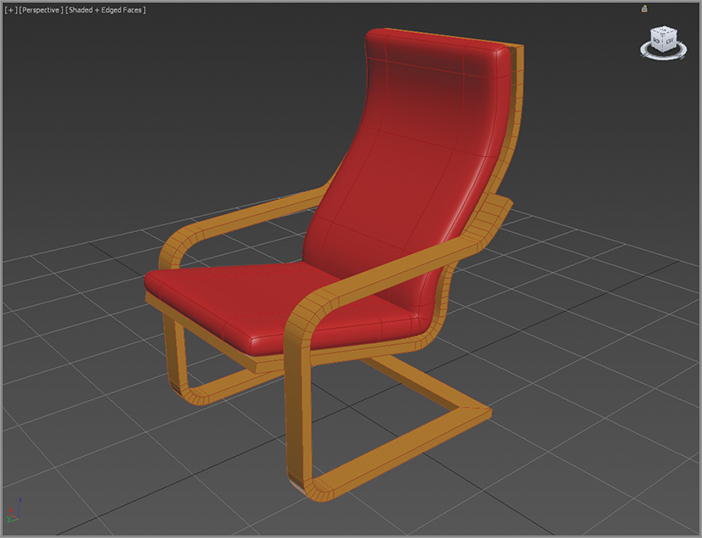
Figure 4-16: The chair for the spline modeling exercise

Adding a Viewport Background Image
Placing an image into the viewport’s background allows you to use that image as a modeling reference. Figure 4-17 show the chair with the measurements.
Figure 4-17: The chair with its measurements

The image will appear in the viewport, but you won’t be able to move it around or see it in any other views. Before you go any further, you need to consider the scale of the image because it will affect the scale of chair. It makes sense to build the chair to a human scale.
Repeat the same steps for the Front viewport, so that you have a front-view image in the Front viewport, and instead use the SplineChair_FrontView.tif image file in the ScenesAssets/Images folder of the Arch Model project, as shown in Figure 4-19.
Figure 4-18: The Viewport Background dialog box

Figure 4-19: The Front and Left viewport images

Building the Splines for the Chair Frame
Now it’s time to create the splines using the following steps:
Figure 4-20: Create vertex points by following the numbers.
Figure 4-21: Select the two vertices on the left side of the chair frame.
Figure 4-22: Use the Fillet tool to create a curve between the new vertices.
Now, these two splines need to be attached to form a single spline. This will allow you to create the bridge piece that runs along the bottom of the frame.
Figure 4-23: Use Connect to create a line between the two separate splines.

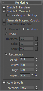
The 3ds Max software has a very cool function you can use to create a shape along a path. The splines you just created are the paths. In the parameters of the editable spline, there is a rollout called Rendering. The controls let you turn on and off the renderability of the spline and specify its thickness in a render of the scene. Once you enable the function, the mesh can be seen in the viewport and will show when rendered. The default 3d mesh that is enabled is a radial mesh, which would make a pipe of sorts, but there is also a rectangular mesh, and both shapes have parameters that can be edited.
Figure 4-24: The Rendering parameters for the chair frame
Click on the Render button in the main toolbar (![]() ) to see the results of the spline rendering, as shown in Figure 4-25.
) to see the results of the spline rendering, as shown in Figure 4-25.
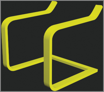
Figure 4-25: The rectangular mesh enabled
You can create the remaining parts of the frame, the seat and back, using the same technique. Using the viewport images, follow the same steps to create the rest of the chair frame. Continue with your chair file or load the SplineChair_Start.max from the Scenes folder of the Arch Model project from the companion web page. This file has the completed seat/back frame, as shown in Figure 4-26.
Figure 4-26: The seat and back frame are attached and connected at the base and top.
Creating the Chair Cushion
For the chair cushion, you can’t use the same spline technique you used on the frame. To create it, you have to return to the same technique you used for the couch: Create a simple box representation and then use NURMS to soften it up.
Figure 4-27: Using SwiftLoop, place an edge loop three units from the bottom of the box.

Figure 4-28: Extrude the poly 20 units in height.
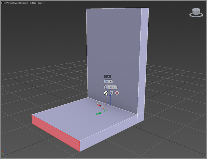
Figure 4-29: Seat cushion box with the SwiftLoops added

Figure 4-30: Select the edge loop on the seat cushion box, and move up and out to match the curve in the chair frame.
To finish things off, add a few extra edges very close to the joint. Then on the back side, move those edges farther away from each other, but keep the edges on the front of the joint very close to each other, as shown in Figure 4-31. This creates a sort of crease because the edges are so close together.
Figure 4-31: Extra edges added at the joint to create a crease.

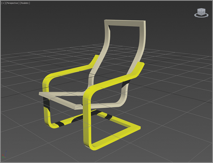
Turn on Use NURMS, go to the Use NURMS tab and turn the Iterations up to 2. This will add more subdivisions and move the cushion. Finally, select the frame and change the color to brown, as shown in Figure 4-32. Take the time to select each object and name it accordingly: Chair Cushion, Chair Frame Arms-Feet, and Chair Frame Seat-Back.
Figure 4-32: The finished chair
Bringing It All Together
Now that the furniture is built, it’s time to furnish the room you built in the last chapter. You can do this by merging the furniture .max files into the room file. Merge allows you to load objects from one .max file into your current file. From the Scenes folder of the Arch Model project folder from the companion web page, open the ArchModel_Final.max file. This is the file that you completed in Chapter 3.
Figure 4-33: In the Merge dialog box, select All and click OK.

Grouping lets you combine objects into a group. A group uses something like an invisible carrying case, called a dummy object, to hold your objects. Select the group and move it around, and the objects will move along with it. A group has its own pivot point. You can transform and modify a group as if it were a single object. If you want to modify an individual object in the group, go to the Group menu and choose Open. A pink bracket will appear. The objects can be individually selected and modified inside the group. When you are finished and want to close the group, choose Group ⇒ Close. Groups can also be nested, meaning you can have a group within a group. When you want to dissolve a group, just select the group and in the Group menu and choose Ungroup.
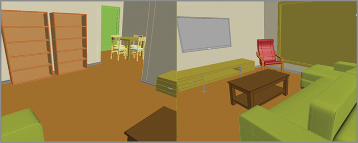
These two pieces of furniture look great, but they don’t fill up the room very much. To help furnish your newly built room, you can merge some prebuilt items into the space to give it a more lived-in look. Repeat steps 1 through 6 for the extra furniture pieces, which can be found in the Chapter 04 Extra Furniture folder in the Scenes folder of the Arch Model project. The room will look better after you merge the objects, as shown in Figure 4-34. The next phase for you may be to create some of your own objects to populate the room.
Figure 4-34: The room with all the merged furniture
- Create more furniture. To start, choose a piece that resembles the ones you’ve already created. Create another chair or table with a frame similar to the chair you completed in the chapter. Create some tables and chairs that feature chrome or stainless steel tube frames or create any style of cushy chair.
- Try to use some of the other Spline tools from previous chapters to create picture frames (Chapter 3, floor molding), lamps and vases (Chapter 2, dresser knobs), and maybe a side table or more chairs.