Chapter 13
Character Studio: Animation
Character animation is a broad and complex field. This chapter introduces you to the basics of using Character Studio and bones for animation. Further investigation into these tools is a must if you want your animation to be full of life and character.
Topics in this chapter include the following:
- Character animation
- Animating the soldier
- Using Inverse Kinematics
Character Animation
The character animation CG specialty is one of the toughest specialties to master. To use one word, good character animation comes down to nuance.
When you animate a character, you have to have a keen eye for detail and an understanding of how proportions move on a person’s body. Setting up a CG character to walk exactly like a human being is amazingly complicated.
Character systems such as Character Studio make it a breeze to outfit characters with biped setups and have them moving in a walk cycle very quickly.
Animating the Soldier
Bipeds can be animated in several ways, including footstep-driven animation and freeform animation. With footstep-driven animation, you add visible Footstep objects to your scene and direct the biped to step onto those footsteps at particular points in time. Footsteps can be added individually or as a set of walk, run, or jump steps; they can be moved or rotated to achieve the desired result and direction. When you use footstep-driven animation, the legs and feet of the biped are not the only things animated; the hips, arms, tails, and all other components are animated as well. However, this approach is rarely the complete solution to your animation needs.
Freeform animation is when you animate the components of the biped manually, as you would animate any other object, such as a bouncing ball.
Animation keys that are added to the selected Biped objects appear in the track bar, just like other objects, where they can be moved, modified, or deleted to adjust the animation.
Adding a Run-and-Jump Sequence
At the end of the previous chapter, you finished rigging the soldier model and added footsteps to check the model. New footsteps can be appended to any existing footsteps. In the next exercise, you will add footsteps to the existing animation cycle.
Continue with the previous soldier model or open the CSSoldierComplete00.max file in the Scenes folder of the Soldier project on the book’s web page at www.sybex.com/go/3dsmax2013essentials. This file has the Biped bones hidden with the soldier model, Bip001, and footsteps showing.
1. Select the Bip001 object. If you have trouble, you can either press the H key or open the Select By Name dialog icon (

) found on the main toolbar. Once you’ve selected the Bip001 object, click Select. Then on the Motion panel, choose Footstep mode (

).
2. Click the Run icon (

) in the Footstep Creation rollout. This will apply a run gait to any footsteps you add to your current footsteps in the Create Multiple Footsteps dialog box.
3. Click the Create Multiple Footsteps icon (

) to open the Create Multiple Footsteps dialog box.
4. Change the number of footsteps to 10 and click OK.
5. In the Footstep Operations rollout, click the Create Keys For Inactive Footsteps icon (

) to associate the new footsteps with the biped.
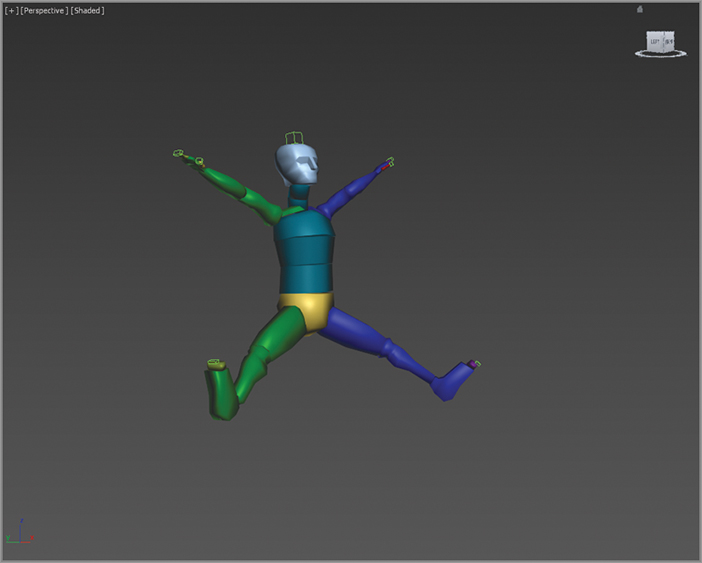
6. Click the Play Animation button. The biped walks through the first 8 steps and then runs through the next 10. As you can see, the run sequence meets the definition of a run, but it is far from realistic. In the next exercise, you’ll learn how to add to or modify a biped’s motion with freeform animation to make a better cycle. For now, click the Play Animation button again to turn off play.
7. Click the Jump button in the Footstep Creation rollout, and then click the Create Multiple Footsteps button.
8. In the Create Multiple Footsteps dialog box, set the number of footsteps to 4 and click OK. Because a jump is defined as a sequence with either two feet or zero feet on the ground at a time, four jump steps will equal two actual jumps.
9. Click the Create Keys For Inactive Footsteps icon to associate the new jump footsteps with the biped.
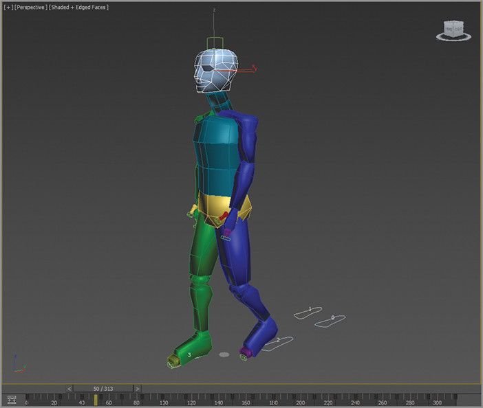
10. Click the Play Animation button. The biped will walk, run, and then end the sequence with two jumps, as shown in
Figure 13-1.
The Actual Stride Height parameter in the Create Multiple Footsteps dialog box determines the height difference from one footstep to the next.
Adding Freeform Animation
When you set your keys initially, you will need to edit them to suit good timing and form. When one part of the body is in one movement, another part of the body is in an accompanying or supportive or even opposite form of movement. When you are walking and your right leg swings forward in a step, your right arm swings back and your left arm swings out to compensate.
You can easily add or modify the biped’s existing animation keys with freeform animation using the Auto Key button and the Dope Sheet. The following exercises contain examples of freeform animation.
Moving the Head
The following steps will guide you through the process of creating head movement for your biped. Continue with the previous soldier model or open the CSSoldierComplete01.max file in the Scenes folder of the Soldier project on the book’s web page at www.sybex.com/go/3dsmax2013essentials. Because you will be working with the biped a lot in this exercise, the biped components have been unhidden and the soldier model has been hidden.
1. Select the Bip001 object and, if necessary, exit the Footstep mode by clicking the Footstep Mode icon.
2. Drag the Time slider to frame 50, approximately the point when the biped lifts its left foot off footstep number 2.
Footsteps are numbered, starting with the number 0 and initially alternating from the left to the right side. They are also color-coded, with blue footsteps on the left and green footsteps on the right.
3. Select the biped’s head and note the animation keys that appear in the track bar, as shown in
Figure 13-2.
4. In the track bar, select the two keys on either side of the current frame. You can do that by dragging a selection box around both keys directly on the track bar; or by selecting one key, then holding the Ctrl key and selecting the other key. Once you do that, right-click either one and then delete them as shown in
Figure 13-3.
5. Click the Auto Key button or press the N key to turn it on. This will allow you to begin creating the animation.
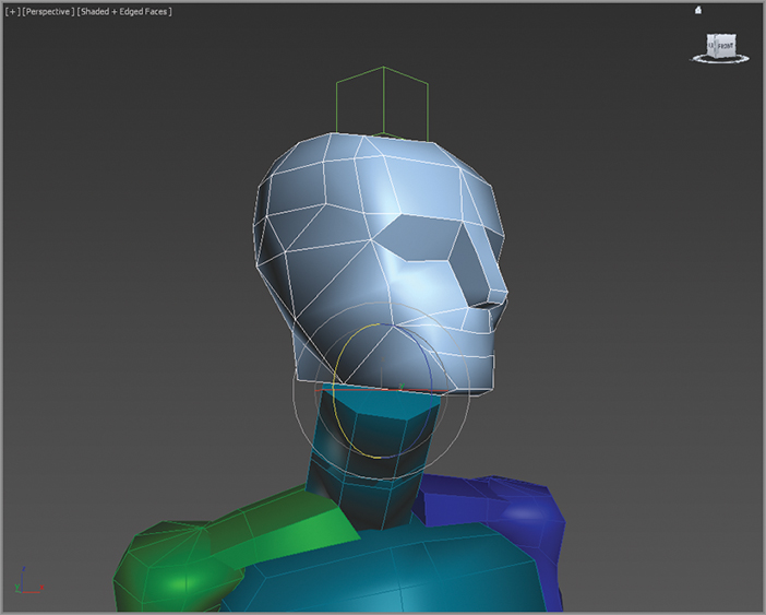
6. Click the Rotate Transform button and rotate the head, as shown in
Figure 13-4, to the left and up, as if the character sees somebody in a second floor window off-screen. A new key will be created at frame 50, recording the time and value of the head’s rotation.
7. Scrub through the Time slider by moving it back and forth. Watch the head rotate from a neutral position to the orientation that you created and then rotate back to the neutral position.
8. Select all the keys between frame 50 and frame 100 (but not keys at frames 50 and 100). Delete them. Doing so will make room for the new key that you are about to create. If animation keys are too close together, the animation could appear jerky.
9. Select the key at frame 50, hold down the Shift key, and drag a copy of the key to frame 90, as shown in
Figure 13-5. Use the readout at the bottom of the 3ds Max® window to drag the key with precision. Copying the key will cause your biped to hold that neck pose for 40 frames, or about 11⁄3 seconds. Scrub the Time slider to review the animation.
10. Select the biped’s left upper arm.
11. In the track bar, select and delete all keys between frames 50 and 100. The animation keys for the arms define their swing motion. If you scrub the Time slider or play the animation, the biped will hold its arm unnaturally stiff for 60 frames because you deleted the animation keys between two points where it holds its hand forward. That’s okay; you’re just making room for some new keys.
12. Move the Time slider to frame 60. This is the location for the first new animation key.
Moving the Arms
Now it’s time to animate the arms, which are essential components in any walk cycle. To do so, follow these steps:
1. Rotate the upper arm upward, so that it points to the same location at which the head is looking.
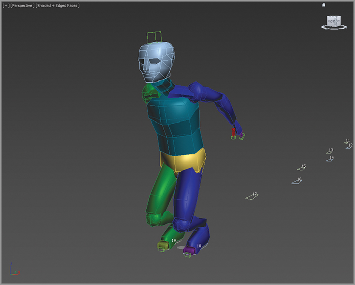
2. Continue adjusting the biped’s left arm, hand, and finger until they appear to be pointing at something, as shown in
Figure 13-6.
3. Double-click on the left upper arm to select it and all of the components below it in the hierarchy.
4. In the track bar, select the key at frame 60, hold down the Shift key, and drag it to frame 85 to create a copy of that key.
5. Drag the Time slider and watch the Perspective viewport. The biped will walk for a bit, notice something off-screen, point at it, and drop its arm while looking forward again before breaking into a run and then a jump.
6. Click the Auto Key button to turn it off.
Completing the Motion Sequence
Continue with the previous soldier model or open the CSSoldierComplete02.max file in the Scenes folder of the Soldier project on the book’s web page at www.sybex.com/go/3dsmax2013essentials.
For additional practice, add keys to the animation of the biped’s arms when it jogs through the run cycle. For example, when the left foot is fully extended and the heel plants on the ground, the right arm should be bent at the elbow and swung forward and slightly in front of the biped’s body. As the right foot swings forward during the next step, the right arm should swing backward and assume a nearly straight posture. Bend each of the spine links and swing both arms backward to prepare the biped for each of the jumps. Use the Body Vertical button in the Track Selection rollout to lower the pelvis into a prelaunch position, as shown in Figure 13-7, before the biped launches into its upward motion. Remember to make sure the Auto Key button is turned on to record all the changes that you make as animation keys.
Modifying Animation in the Dope Sheet
To change the animation that is generated with Character Studio, you will edit the keyframes of the biped once you are happy with the base animation cycle. For this, you need to use the Track View–Dope Sheet. The Track View–Curve Editor, as you have already seen in Chapter 5, “Animating a Bouncing Ball,” is used to edit the function curves between animation keys; however, the Track View–Dope Sheet interface is cleaner and is used to edit the specific value and position of the keys. It is not a different set of keyframes or animation; it’s just a different way of editing them. Furthermore, access to editing the footstep keys is available only in the Dope Sheet. In the next exercise, you will add individual footsteps and modify the footstep timing in the Dope Sheet to make the biped dance and jump.
Adding Footsteps Manually
In the following steps, you will manually add footsteps to your biped character. Continue with the previous soldier model or open the CSSoldierComplete03.max file in the Scenes folder of the Soldier project on the book’s web page at www.sybex.com/go/3dsmax2013essentials. This is the rigged and skinned soldier biped with no footsteps applied.
1. Select a biped component and enter the Footstep mode.
2. In the Footstep Creation rollout, click the Walk button and then the Create Footsteps (At Current Frame) icon (

).
3. In the Top viewport, click in several locations around the biped to place alternating left and right footsteps to your liking.
4. Change the gait to a jump, and then click the Create Footsteps (Append) icon (

) to create additional footsteps. Create about 16 footsteps in all.
5. When you are done, use the Move and Rotate transforms to adjust the footstep locations and orientations as desired. Your Top viewport should look similar to
Figure 13-8.
6. In the Footstep Operations rollout, click the Create Keys For Inactive Footsteps icon and then play the animation.
7. Character Studio doesn’t have a collision-detection feature, so it is very possible that limbs will pass through one another, which is quite uncomfortable in real life. If this happens, the footsteps must be modified to eliminate these conditions. If necessary, move any footsteps that cause collisions or other unwanted conditions during the playback.
Using the Dope Sheet
In Chapter 5, you experimented with the Track View–Curve Editor and learned how to adjust the values of animation keyframes. When the Track View is in Dope Sheet mode, frames are displayed as individual blocks of time that may or may not contain keys. Although you cannot see the flow from key to key that the Curve Editor displays with its curves, the Dope Sheet mode has its advantages. For one, the Dope Sheet has the ability to add Visibility tracks to control the display of an object, as well as Note tracks for adding text information regarding the keys as reminders.
Using the Track View–Dope Sheet, you can adjust the point in time when a foot plants on or lifts off the ground, how long the foot is on the ground, and how long the foot is airborne. Rather than appearing as single-frame blocks in the Dope Sheet as other keys do, footstep keys appear as multiframe rectangles that identify each foot’s impact time with the footstep. Let’s try the Dope Sheet on for size here:
1. Make sure you are in Footstep mode. This will select the biped’s footsteps.
2. In the main toolbar, choose Graph Editors ⇒ Track View–Dope Sheet. The Dope Sheet will open.
3. In the Navigation pane on the left, scroll down until you find the Bip001 Footsteps entry. Expand the Bip001 Footsteps entries. The footstep keys appear as rectangles in the Key pane. As expected, the left keys are colored blue and the right keys are colored green. If necessary, click the Zoom Region icon (

) in the lower-right corner of the Dope Sheet window and drag a zoom window around the footstep keys, as shown in
Figure 13-9. The region will expand to fit the Key pane.
4. Select a few footsteps in the viewport or select the green- and blue-colored rectangles (holding Ctrl to select multiple footsteps).
The white dot on the left side of a selected key identifies the frame when the heel of the biped’s foot first impacts the footstep. The white dot on the right side of a selected key identifies when the biped’s foot lifts off a footstep, as shown in
Figure 13-10. A blue key (rectangle) overlapping a green key (rectangle) indicates that both feet are on the ground. A vertical gray area with no footstep indicates that the biped is airborne and neither foot is on the ground.
5. Select the first key (numbered 0), place the cursor over the right edge of the key, and then drag the dot to the right to extend the length of time that the biped’s foot is on the ground.
You can’t move the end of one footstep key beyond the beginning of another one, and you must maintain a one-frame gap between same-side footsteps.
6. The double vertical line in the Dope Sheet’s Key pane is another Time slider that allows you to scrub through the animation. Drag the Dope Sheet’s Time slider to a point in time when the biped is airborne.
Increasing the airborne time by increasing the gap between footsteps will also boost the height to which the biped rises, acting against the gravitational force pushing it downward.
7. Select the last four jump keys and drag them to the right to create a gap approximately 30 frames wide, as shown in
Figure 13-11. Doing so will cause the biped to be airborne for about one second.
It is possible to move a footstep beyond the limits of the active time segment in the Dope Sheet. Use the Alt+R key combination to extend the active time segment to include all existing keys.
8. Move the Time slider to the frame when both feet are planted before the jump starts. Turn on the Auto Key button.
9. Deselect any keys by clicking a blank area in the Key pane.
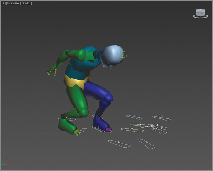
10. To prepare the biped to leap, turn on Auto Key and then select the Bip001 object and move it downward, causing the biped to bend its knees more. Rotate the spine links, neck, and head to bend the torso forward and tuck the chin. Rotate both arms backward into a pre-jump posture, as shown in
Figure 13-12. Be sure to choose Local as the reference coordinate system for the Rotate transform.
11. Move the Time slider forward until the biped is at the apex of the jump. Rotate the biped’s components into positions you like, such as the split shown in
Figure 13-13. Delete any animation keys that may interfere with your desired motion, and turn off Auto Key.
The CSSoldierComplete04.max file in the Biped Scene Files folder on the book’s web page contains the completed exercise so you can check your work. This file has the soldier model unhidden and the biped hidden. Play the animation and see how it looks; modify where needed.
As you saw in this section, there are several ways to animate a biped, including the footstep-driven method, the freeform method, and a combination of techniques. You can also modify the animation in the track bar, with the Auto Key button, and with Track View–Dope Sheet.
Using Inverse Kinematics
When a hierarchy is set up through linking, the result is a kinematic chain. Transforms are passed from a parent object to all of the child objects down the chain. Imagine your arm is a system of linked 3ds Max objects; when you pivot your forearm (the parent) at the elbow, your hand (the child) and your fingers (the descendants) are also transformed to maintain the relationship between the objects. This is known as Forward Kinematics (FK) and is the default method of passing transforms in a hierarchy.
When Inverse Kinematics (IK) is used, the child object is transformed while the parent and ancestor objects maintain their relationships throughout the chain. Using the same arm analogy, lifting your arm by grabbing and pulling up on a finger would raise the hand, which would raise the forearm, causing a curl at the elbow. With IK, the end of the chain, the child, is positioned in your animation and the rest of the chain upstream rotates and pivots to fit the new layout of the chain to achieve a possible pose. IK setups require the use of an IK solver to determine how the parent objects react to the child transforms and joint constraints to prevent unnecessary twists in the motion.
In the following exercise, you will play some more with toys of war by linking a machine gun mounted on a tank model. Here, the goal is to arrange the IK setup so that the gun pivots vertically at the joints only and then pivots at the turret.
Linking the Objects
Open the IKGun1.max file in the Scenes folder of the Soldier project on the book’s web page at www.sybex.com/go/3dsmax2013essentials. The machine gun unit consists of the gun itself, two two-component pivot assemblies, two shafts, and the turret ring. The gun is at the top of the hierarchy, and the turret is at the bottom
1. In the main toolbar, click on the Select and Link tool (

). Begin by dragging and linking the Gun object to the PivotTop object, the small, blue cylindrical object near the gun. The PivotTop object will flash briefly to signify that is has been linked.
2. Continue creating the hierarchy by also linking the PivotTopRing to PivotTop, PivotTop to Shaft1, and then Shaft1 to PivotBottom.
3. Complete the setup by linking PivotBottomRing to PivotBottom, PivotBottom to Shaft2, and Shaft2 to Turret.
4. Go to the main toolbar and select Tools ⇒ New Scene Explorer. This opens a Scene Explorer, as shown in
Figure 13-14.
The Scene Explorer is for viewing, sorting, filtering, and selecting objects as well as additional functionality for renaming, deleting, hiding, and freezing objects, creating and modifying object hierarchies, and editing object properties. The Scene Explorer looks just like the Select From Scene dialog box (); the difference is the Scene Explorer allows you to edit your scene while keeping the Scene Explorer open.
Creating Joint Constraints
The gun assembly should only be able to rotate in certain ways. The gun itself should only pivot perpendicular to the PivotTop object, for example. This is accomplished by constraining the Rotate transform for the PivotTop object, the parent of the gun, to a single axis. The transforms can further be restricted by limiting the range of motion an object can rotate within an acceptable axis. This method is used to prevent the gun barrel from rotating to the point where it disappears within the tank body. Both of these tasks are accomplished under the Hierarchy tab of the Command panel, as you will see in the following steps:
1. In the Command panel, click the Hierarchy tab (

).
2. Click the IK button and then, in the Inverse Kinematic
s rollout, click the Interactive IK button, as shown in
Figure 13-15. The Interactive IK button will turn blue to indicate that this feature is active and any transforms applied to objects in the hierarchy are applied in IK mode.
3. In the Perspective viewport, select and move the Gun object along the X-axis. The gun’s orientation changes and all of the hierarchy elements, including the turret, change to maintain the connection, but they all rotate oddly. This is because the orientation at the joints is not constrained to a single axis or limit of degrees.
4. Undo any transforms that were applied (

).
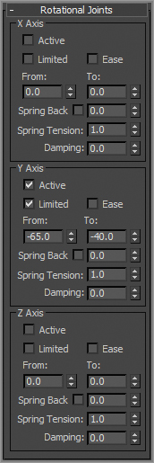
5. In the Scene Explorer, select the PivotTop object. Then in the Hierarchy panel, Rotational Joints rollout, uncheck the X Axis and Z Axis Active check boxes.
6. Check the Limited check box in the Y-axis section. Increase the From parameter to approximately –65 by dragging the spinners. The Pivot and its children will rotate in the viewport and then snap back to their original orientations when the mouse is released. Drag the To spinner to approximately –40, as shown in
Figure 13-15. Limiting the orientation restricts how far the object can rotate in a particular axis, and dragging the spinners instead of typing in the values gives visual feedback regarding the axis about which the object is rotating.
7. Select Shaft1 and uncheck the Active option for the X-, Y-, and Z-axes in the Rotational Joints rollout. Repeat the process for the Shaft2 and Gun objects. None of these objects needs to rotate on their own; they just need to follow their parent objects.
8. Select the PivotBottom object. Check the Active and Limited options in the Y-axis area. Set the From value to –4 and the To value to 30. Uncheck the X-axis and Z-axis Active options.
9. Select the Turret object. Only the Z-axis option should be checked, so the turret can only rotate laterally and not flip over. Do not check the Limited option; the turret should be able to rotate freely.
10. In the Object Parameters rollout, check the Terminator option to identify the turret as the top object in the IK structure, as shown in
Figure 13-16.
11. Select the Gun object and then click the Link Info button at the top of the Hierarchy panel. In the Rotate section of the Locks rollout, check the X option. The gun should not rotate in any axis except the local X-axis.
12. Select the Turret object and in the Link Info rollout, check the X, Y, and Z options in the Move section, to lock any movement for the turret. The turret should be fixed in place. In a complete 3ds Max scene, the turret would be linked to a larger structure to define its transforms.
13. Click the IK button at the top of the Hierarchy panel, and then click the Interactive IK button again to turn it on if necessary. Test your IK chain by moving the gun. As it moves, the other objects in the chain will reorient to maintain the proper relationships with their parent objects. Turn off the Interactive IK button when you are done.
Applying the IK Solver
An IK solver calculates the controls required to position and orient the members of an IK chain when one or more members is moved or rotated. The IK solver defines the top of the chain and identifies the goal, or the base of the chain. The IK solver precludes the need to activate the Interactive IK mode in the Hierarchy panel whenever IK is required.
The two appropriate IK solvers for this situation are the HI (History Independent) solver and the HD (History Dependent) solver. The HI solver is better suited for long animation sequences and character animation, and the HD solver is better suited for machine animation. Because the goal for this animation for this setup is for a machine, in this case a tank, the HD solver will be used here.
Open the IKGun2.max file in the Scenes folder of the Soldier project on the book’s web page at www.sybex.com/go/3dsmax2013essentials.
1. Undo any transforms that were applied in your own scene during the previous exercise if necessary. You can undo a string of commands easily by right-clicking the Undo button in the main toolbar.
NOTE Right-click the Undo button in the main toolbar to see a list of the recent changes to the scene, with the most recent changes at the top of the list. Click on the entry in the list that defines the last command that you want undone. That command and all of the commands above it will highlight. Press the Enter key to undo all the selected commands.
2. Choose Edit ⇒ Hold from the main menu. A few IK operations, including applying an IK solver, are not always undoable through the Undo command. If the result of the IK solve is not correct, choose Edit ⇒ Fetch to restore your scene to the point just before you executed the Edit ⇒ Hold.
3. Turn off Interactive IK.
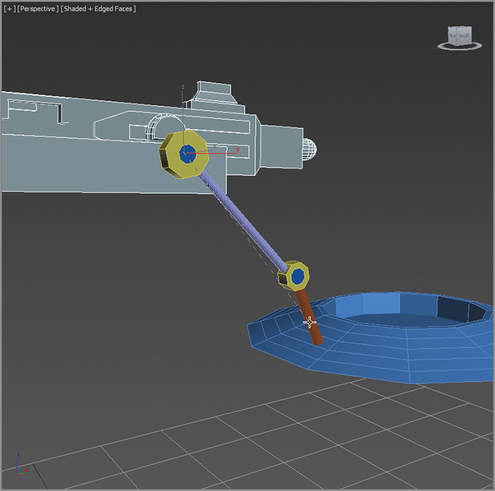
4. Select the gun and choose Animation ⇒ IK Solvers ⇒ HD Solver
. A rubber-band line will stretch from the gun’s pivot point to the cursor, as you can see in
Figure 13-17. Place the cursor over the Shaft2 object and click to define it as the end of the IK chain. The IK chain should now be bound to the object that has been designated as the Terminator.
NOTE When the cursor is moved over the other viewports while an IK solver is being assigned, the view will update to show the rubber-banding line projecting from the object to the cursor in that particular viewport. The viewport does not have to be the active viewport for this viewport change to occur.
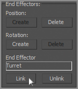
5. The End Effectors behaves as the pivot point of the Terminator object and can be used to straighten out the chain without actually moving the child object. On the Motion panel, in the IK Controller Parameters rollout, click the Link button in the End Effectors area and then click on the turret. Turret appears in the End Effector Parent field, as shown in
Figure 13-18.
6. Select the gun and use the Move Transform to test your IK setup. Moving the gun forward, backward, up, or down will now cause the two pivots to rotate within their limits.
The HD solver’s IK components are not listed in the Select Objects dialog box because they act on behalf of the objects to which they are assigned. To modify any of its properties, select the object and open the Motion panel of the Command panel. The IK Controller Properties rollout contains the options for modifying the IK chain.
The Essentials and Beyond
This chapter introduced you to animating characters with Character Studio. Using the Biped system, you can quickly create and adjust the substructure that controls a 3D model. Once the Physique modifier associates or skins the model to the biped, character animation can be added using footstep-driven or freeform animation.
IK is used throughout mechanical design and character animation, and it is another 3ds Max tool that you may find invaluable once its workflow becomes second nature to you. The exercises in this chapter examined the basics of an IK setup and the basic use of an IK solver for a mechanical animation of the tank. The IK setups can include several IK chains controlling the transforms for different components of the same model. Easily selected controls can be placed in the scene for simple selection and manipulation of a complex model’s components. IK can also be used for organic character animation, because the 3ds Max program has different types of IK for character work as well (such as the HI IK or Limb Solver IK). This chapter covered only one type of IK (using the HD solver) for a simple use of IK. Most practical applications will use the HI system; however, for the purposes of this book, familiarizing yourself with the simpler HD solver primes you for further study in 3ds Max IK systems.
Additional Exercises
- Add different head or arm movements to the current footsteps on your soldier.
- Animate the soldier character running and dodging enemy fire.
- Create other object hierarchies to link together and create Inverse Kinematics.