Chapter 16
mental ray and HDRI
This chapter will show you how to render your scene using Autodesk® 3ds Max® software’s Scanline Renderer and how to create reflections and refractions using raytracing. In addition, this chapter will introduce you to the popular mental ray Renderer and HDRI lighting workflow.
Topics in this chapter include the following:
- mental ray Renderer
- Final Gather with mental ray
- HDRI
mental ray Renderer
mental ray is a popular general-purpose renderer that has fantastic capabilities. One of mental ray’s strengths is its ability to generate physically accurate lighting simulations based on indirect lighting principles. Indirect lighting is when light bounces from one object in a scene onto another object. In addition, incandescence or self-illumination from one object can light other objects in the scene. Direct light, such as from an omni light, is not necessarily required. Another thing to consider is that mental ray’s reflections and refractions take on very real qualities when set up and lighted well.
Enabling the mental ray Renderer
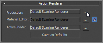
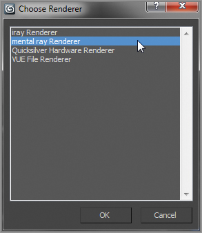
To enable mental ray, in the main menu, choose Rendering ⇒ Render Setup to open the Render Setup dialog box. On the Common tab, scroll down to the Assign Renderer rollout, and then click the ellipsis button for the Production entry shown in Figure 16-1. This opens the Choose Renderer dialog box shown in Figure 16-2.
In the Choose Renderer dialog box, highlight mental ray Renderer and then click OK. Once the mental ray Renderer is assigned, you can make it the default renderer by clicking the Save As Defaults button on the Assign Renderer rollout. Now the Render Setup dialog box opens with the mental ray controls in tabs.
mental ray Sampling Quality
Once the mental ray Renderer is enabled, click the Renderer tab in the Render Setup dialog box. The following is a brief explanation of the render settings most useful for you in your work.
Under the Sampling Quality rollout, shown in Figure 16-3, are the settings that let you control the overall image quality of your renders.
The Minimum and Maximum Samples Per Pixel values specify the number of times mental ray samples a pixel to determine how best to anti-alias the result to avoid jagged lines. Spatial Contrast values for Red, Green, Blue, and Alpha determine the exact sample level within that range. The lower the values set for Spatial Contrast, the higher the sample rate, leading to a smoother render at a higher render time.
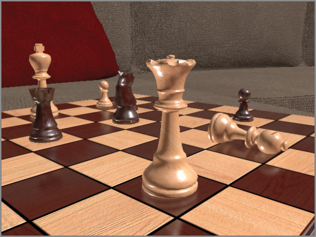
The image shown in Figure 16-4 was rendered with a Minimum Samples Per Pixel value of 1/16 and a Maximum Samples Per Pixel value of 1, using a Spatial Contrast setting of 0.1 for all four RGBA values. With the Minimum Samples Per Pixel value at 4, the Maximum Samples Per Pixel value at 16, and the Spatial Contrast value at 0.04 for RGBA, the render becomes much cleaner, with an acceptable increase in render times, as shown in Figure 16-5.
Final Gather with mental ray
A popular feature in mental ray is indirect illumination—the simulation of bounced light (explained in the next section). In the tabs at the top of the Render Setup dialog box, click the Indirect Illumination tab. There are three rollouts, the first of which we will explore further:
- Final Gather
- Caustic And Global Illumination (GI)
- Reuse (FG And GI Disk Caching)
Final Gather
Final Gather is a method of mental ray rendering for estimating global illumination (GI). In short, global illumination is a way of calculating indirect lighting. This way, objects do not need to be in the direct path of a light (such as a spotlight) to be lit in the scene. In short, mental ray accomplishes this by casting points throughout a scene. These light points are allowed to bounce from object to object, contributing light as they go, effectively simulating how real light photons work in the physical world.
This type of rendering can introduce artifacts or noise in the render. Finding the right settings to balance a clean render and acceptable render times is an art form all its own and is rather difficult to master. Figure 16-6 shows the Final Gather rollout. Some of Final Gather’s options, including how to deal with quality and noise, are explained next.
Basic Group
These are the most important parameters in the Basic section of the Final Gather rollout; they set the accuracy and precision of the light bounces, thereby controlling noise.
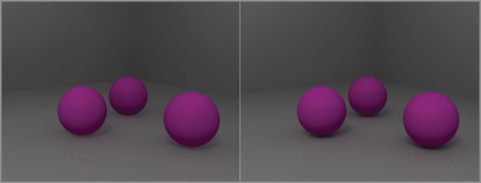
FG Precision Presets Slider Sets the accuracy level of the Final Gather simulation by adjusting settings for the renderer such as Point Density, Rays Per Point, and Interpolation. Use this slider first in setting how good your render’s lighting looks. In
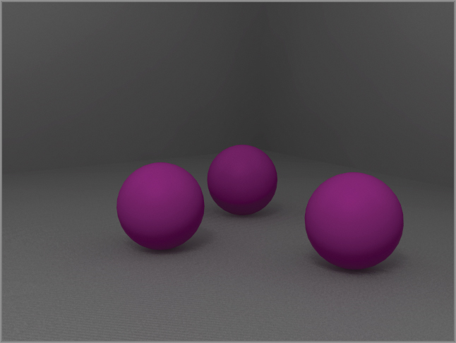
Figure 16-7 (left image), three spheres are rendered with a Draft setting for Final Gather, while
Figure 16-7 (right image) is set to High. Notice the right image is a cleaner render, and it also shows more of the background and the spheres than does the Draft quality in the left image. This slider will adjust the settings for several of the values covered in the following list.
Initial FG Point Density This multiplier is one of the settings adjusted by the FG Precision Presets slider, but it can also be set manually. This value sets the quantity and density of FG points that are cast into the scene. The higher the density of these points, the more accurate the bounced light appears, at a cost of render time.
Rays Per FG Point This value is controlled by the Precision slider but can also be manually set. The higher the number of rays used to compute the indirect illumination in a scene, the less noise and the more accuracy you gain, but at the cost of longer render times.
Interpolate Over Num. FG Points Interpolation is controlled by the FG Precision Presets slider as well as manual input. This value is useful for getting rid of noise in your renders for smoother results. Increasing the interpolation will increase render times, but not as much as increasing the Point Density or Rays values.
Diffuse Bounces The number of bounces governs how many times a ray of light can bounce and affect objects in a scene before stopping calculation. If you set the bounces higher, the light simulation will be more accurate, but the render times will be costly. A Diffuse Bounces setting of 1 or 5 is adequate for many applications.
Figure 16-8 shows the same render of the spheres as
Figure 16-7, but with a Diffuse Bounces value of 5. This render is brighter and also shows color bleed from the purple spheres onto the gray floor.
Advanced Group
The Advanced group of settings gives you access to additional ways of controlling the quality of your Final Gather renders. Some are described next in brief. You should experiment with different settings as you gain more experience with Final Gather to see what settings work best for your scenes.
Noise Filtering (Speckle Reduction) This value essentially averages the brightness of the light rays in the scene to give you smoother Final Gather results. The higher the filtering, the dimmer your Final Gather simulation, and the longer your render times will be. However, the noise in your lighting will diminish.
Draft Mode (No Precalculations) This setting allows you turn off a good number of calculations that mental ray completes prior to rendering the scene. Enabling this setting results in a faster render for preview and draft purposes.
Max. Reflections This value controls how many times a light ray can be reflected in the scene. A value of 0 turns off reflections entirely. The higher this value, the more times you can see a reflection. For example, a value of 2 allows you to see a reflection of a reflection.
Max. Refractions Similar to Max. Reflections, this value sets the number of times a light ray can be refracted through a surface. A value of 0 turns off all refraction.
The mental ray Rendered Frame Window
When you render a frame using the 3ds Max program, the Rendered Frame window opens, displaying the image you just rendered. When you render with mental ray, an additional Control panel is displayed under the Rendered Frame window, as shown in Figure 16-9.
This Control panel gives you access to many of the most useful settings in the Render Settings dialog box so you can adjust render settings easily and quickly.
mental ray Materials
For the most part, mental ray treats regular 3ds Max maps and materials the same way the Default Scanline Renderer does. However, a set of mental ray–specific materials exists to take further advantage of mental ray’s power.
The mental ray Arch & Design material works great for most hard surfaces, such as metal, wood, glass, and ceramic. It is especially useful for surfaces that are glossy and reflective, such as metal and ceramic.
To showcase these materials, let’s retexture a few of the features from the room from Chapter 10, “Introduction to Materials: Interiors and Furniture.”
1. Set your project to the Arch Model project that you downloaded from the web page. Open the
ArchModel_mentalray_start.max file from the
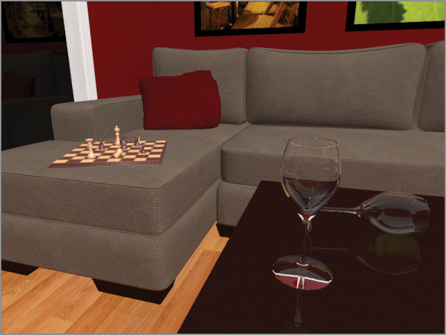
Scenes folder of the mental ray Scene Files project on the book’s web page. This file has mental ray already assigned as the renderer. The scene has the room, and the furniture textured. There are no lights in the scene; but because mental ray is the assigned renderer, it utilizes the default lights to generate a lighted scene, as shown rendered in
Figure 16-10. mental ray renders the materials from the previous chapter. Some look the same, but others don’t look so good—the coffee table in particular. Start with it.
2. Open the Slate Material Editor; at the top of the View Area. You will see a tab called View 1; it holds all the materials you built in the previous chapters for the room. To keep the materials separate and organized, create another tab for the mental ray materials. To create a new tab, right-click in the blank area next to the tabs, as shown in
Figure 16-11, and create a new View Area. Name it mental ray
.
3. Drag an Arch & Design material to the new View Area from the mental ray material section of the Material/Map browser.
4. Double-click on the title of the node; this will display the Arch & Design material in the Material Parameter Editor. Name the material Dark Wood Coffee Table.
5. Drag a bitmap from the Maps rollout into the input socket of the Arch & Design material. This will bring up an Explore window; choose the Dark Wood_Grain.tif. Leave all the other parameters at the default.
By default, Arch & Design materials have reflection enabled. The area below the Diffuse group in the Parameter section of the Slate is the Reflection group of parameters. Reflections for this material are calculated using the Reflectivity and Glossiness values. The higher the Reflectivity value is, the clearer the reflections are. The Glossiness value controls the blurriness of the reflections from sharp (a value of 1) to completely blurred (a value of 0). When you blur your reflections, the blurrier they are and the noisier they will be in the render. You can use the Glossy Samples value to increase the quality of the blurred reflections once you set Glossiness to anything less than 1.
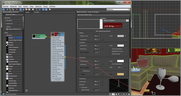
6. Drag a wire from the material’s output socket to the Coffee Table in the viewport, as shown in
Figure 16-12.
Render the Camera viewport to see the new material on the coffee table. The Coffee Table Material is too reflective.
7. In the Reflection group, change the Reflectivity to 0.4 and the Glossiness to 0.4. When it renders, there is a lot of graininess in the reflection.
8. Change the Glossy Samples to 40; this will shoot more “rays” into the glossiness and change the graininess.
9. Check the box next to Fast (Interpolate); this will help to speed up the render and works best when the reflections are on a flat surface. Render the camera to see the results, as shown in
Figure 16-13.
Multi/Sub-Object Materials and Arch & Design
By using the Multi/Sub-Object material and dragging the individually created materials to the selected polygons, you can use the same technique for the window that you used in Chapter 10. The difference now is you will use the Arch & Design material instead. The window is divided into two materials: shiny white for the frame and a shiny transparent material for the glass.
1. In the Slate Material Editor, you’ll create a shiny white material. Drag an Arch & Design material to the mental ray View Area. Change the Diffuse color to R: 0.8, G: 0.0, B: 0.0 and rename it White Window Frame.
2. Based on what you know about reflections from the previous steps, the default reflections are too high, especially for the frame on the window. In the Reflections group, change the Reflectivity to 0.4 and the Glossiness to 0.4.
3. Select the window and enter Element mode (Graphite Modeling Tools ⇒ Polygon Modeling)

. Select all the polygons for the window frame. In the Material Editor toolbar, select the Assign Material to Selection

.
4. Back in the Material Editor, drag an Arch & Design material to the mental ray View Area. In the Refraction group, change the Transparency to 1.0. In the toolbar, select the Show Background in Preview icon (

). This will place a checker pattern behind the sample sphere to make the transparency easier to edit. Double-click on the sphere icon on the Material node. This will enlarge the sample sphere, making it easier to edit.
5. Render the Camera01 viewport. If it isn’t loaded into a viewport, just select a viewport and press the C key. This will change the viewport to a camera. If there are multiple cameras in the scene, a Camera List dialog box will appear, allowing you to choose a specific camera to apply to the viewport. You can see that the window and frame look very similar to the Standard materials, but the coffee table looks significantly better. When using mental ray, Arch & Design materials are superior. Sometimes the look of a particular object can change depending on the camera angle and lighting. Let’s keep an eye on the window to see if the look maintains the realism you are after.
Arch & Design Templates
Arch & Design materials have a special feature: templates. Templates provide access to already-created materials and parameters for different types of materials such as wood, glass, and metal. These templates can also be used as a starting point for material creation. For the wine glasses in the scene, you will use a template material.
1. In the Material Editor, drag an Arch & Design material into the View Area. Double-click on the title of the Material node to load the parameter in the Parameter Editor. Name the material Wine Glass.
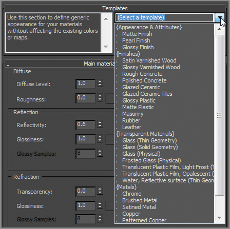
2. At the top of the parameters is the Templates rollout, shown in
Figure 16-14. Click on the Select A Template down arrow; from the drop-down menu under Transparent Materials, select Glass (Solid Geometry).
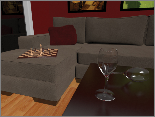
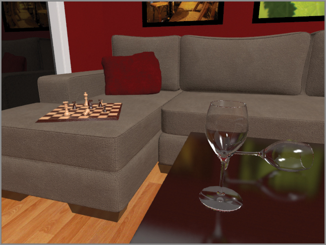
3. Apply the material to the Wine Glass objects in the scene. Render the scene. The wineglasses look good, but there is a blue tint to the glass that is unappealing.
4. Back in the Material Editor, in the Refraction group, click on the color swatch next to Color. Change the RGB values to R: 1.0, G: 1.0, B: 1.0. For future reference, this is a way to create color-tinted glass. Render the scene. This time the glasses look stunning! The final results are shown in
Figure 16-15.
The Arch & Design material type is an elaborate construct of mental ray shaders, and with proper lighting it can make any render look special. If you open the ArchModel_mentalray_end.max file, you will see several materials examples beyond what you created in the previous exercise.
3ds Max Photometric Lights in mental ray Renderings
Many of the parameters for photometric lights are the same as or very similar to the standard lights you looked at in Chapter 14, “Introduction to Lighting: Interior Lighting.” Here, you see the parameters that are specific to photometric lights. Photometric lights simulate real lighting by using physically based energy values and color temperatures.
1. Either continue with the file you are working with or open the ArchModel_mentalray_light.max file from the Scenes folder of the mental ray Scene Files project from the book’s web page.
2. In the Menu Bar, choose Create ⇒ Lights ⇒ Photometric Lights ⇒ Target Light to create a photometric target light.
3. When you click on the photometric target light, you will get a pop-up recommending that you use the mr (mental ray) Photographic Exposure Control. Click OK.
4. In the Left viewport, click to create the light from ceiling and then drag down to the floor. Make sure the light stays within the room.
5. Switch to the Top viewport and move the light and its target so it is above the coffee table. The easiest way to make sure you select both the light and target is to select the blue string that runs between the two and then just use the Move tool. Once the light is in the scene, change the viewport rendering type to Realistic.
6. With the light still selected, go to the Modify panel. The first rollout under the modifier stack is Templates.
This rollout gives you access to several light type presets to save you time in creating a light. Feel free to play around with the different presets and render the room frame a few times to see the differences before continuing with the exercise and the next step.
7. In the Select A Template drop-down menu, select Recessed 75W Lamp (Web).
A photometric light with a “web” distribution essentially defines the light’s behavior and the light it casts. Lighting manufacturers provide web files that model the kinds of lights they make, so using these distribution patterns as templates will give you a lot of options in simulating real-world lights, such as this 75-watt recessed lamp.
Figure 16-16 shows the distribution pattern for this light as shown in the Command panel.
8. You need to take care of some basic stuff now, so with the light still selected, open the General Parameters rollout and check the Targeted box. You originally created a targeted light but when you used the template, it took away the target. Having a target on a light makes it easier to edit the light’s position. Checking this box turns the target back on for the light.
9. Click the Shadows On box to turn it on. From the drop-down menu, choose Ray Traced Shadows.
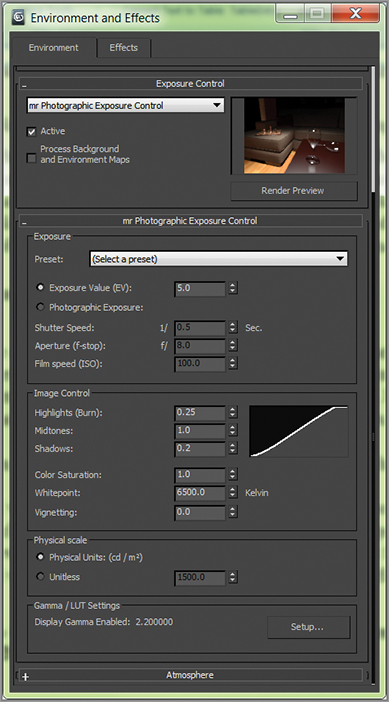
10. Make the Camera001 viewport active and on the Menu Bar, choose Rendering ⇒ Exposure Control and click the Render Preview button, as shown in
Figure 16-17. The preview may show as either very bright or very dark at first. If so, the preview function will work perfectly once you render a frame for the first time.
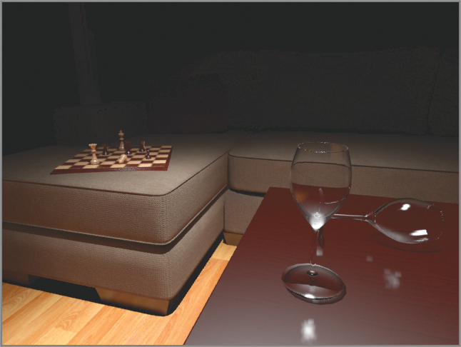
11. Under the mr Photographic Exposure Control rollout, select Exposure Value (EV), if it isn’t already selected. Set some different values for the EV and see what happens in the Render Preview dialog box. The higher the EV number, the darker the scene will be. Set the EV value to 5 or so and render, as shown in
Figure 16-18. You can continue to work with the EV value to experiment with the luminance level. When you’re finished experimenting, be sure to set the EV back to 5 and close the Environment And Effects dialog box.
Exposure controls adjust output levels and the range of colors of a rendering. These controls are similar to real-world film exposure settings on a physical camera.
Photometric Light Parameters
Now let’s look in the Command panel at the photometric light’s Intensity/Color/Attenuation rollout for the 75W light, as shown in Figure 16-19.
The Color group of parameters controls the color temperature of the light, which you can set either with a color value or in Kelvin degrees, just as with real-world photographic lights. In the drop-down menu, there are different color/temp settings. The default is D65 Illuminant (Reference White).
The Intensity group of parameters controls the strength or brightness of the lights measured in lm, cd, or lx at:
lm (lumen) This value is the overall output power of the light. A 100-watt general purpose lightbulb measures about 1750 lm.
cd (candela) This value shows the maximum luminous intensity of the light. A 100-watt general-purpose lightbulb measures about 139 cd.
lx at (lux) This value shows the amount of luminance created by the light shining on a surface at a certain distance.
The parameters in the Dimming section are also used to control the intensity of the light. When the Resulting Intensity box is checked, the value specifies a multiplier that dims the existing intensity of the light and takes over control of the intensity. Picking up from the last step in the previous exercise, let’s start to experiment with these values in the following steps:
1. With the 75W light still selected, go to the Modify panel and, in the Color group under the Intensity/Color/Attenuation rollout, click the button next to Kelvin and change the value to 4500. This will give the light a bit more warmth by adding more yellow/red.
2. In the Dimming group, uncheck the box next to the 100% spinner under Resulting Intensity to enable the Intensity parameter.
3. In the Intensity group, select cd and set the cd amount to 4000. This will brighten things up a bit.
The scene still looks a bit dark and the shadows are very dark; they look like black holes. You will use Final Gather to brighten up the overall render. So far, you have used Final Gather’s default settings. The one thing you need is for the rays that are generated by the light to bounce. The more bounces the light makes, the more luminance there is in the room—but more bounces slow down the render. For the best and most efficient results, try to balance the bounces with exposure control and the intensity of the light.
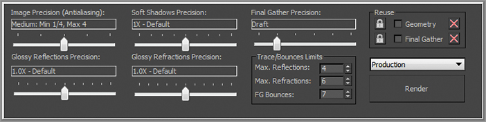
5. When you are rendering with mental ray, the mini Final Gather panel in the Rendered Frame window is available for quick changes. Most of these controls also have a home in the Render Setup dialog box, and changing the value in one dialog box updates the corresponding value in the other. In the mini panel below the Rendered Frame window, as shown in
Figure 16-21, change FG Bounces to 7. Render and compare the resulting render shown in
Figure 16-20 to
Figure 16-22.
Figure 16-22 is the final room.
3ds Max Daylight System in mental ray Renderings
The Sunlight and Daylight systems simulate sunlight by following the geographically correct angle and movement of the sun over the earth. You can choose location, date, time, and compass orientation to set the orientation of the sun and its lighting conditions. You can also animate the date and time to achieve very cool time-lapse looks and shadow studies. In essence, this type of light works really well with mental ray and Final Gather. In this exercise, you will use it in the most basic way, using all of its defaults:
1. Open the ArchModel_mentalray_final.max file from the Scenes folder of the mental ray Scene Files project on the book’s web page. This is the file you ended with after applying the Arch & Design textures earlier in the chapter.
2. In the Menu Bar, choose Create ⇒ Lights ⇒ Daylight System.
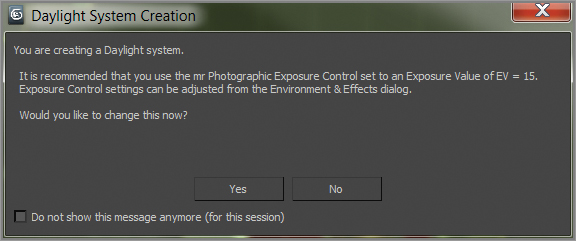
A Daylight System Creation warning will come up, as shown in
Figure 16-23, asking if you want to change the exposure controls to suit the Daylight system. Click Yes.
3. In a Top viewport, click and drag at the center of the scene. This will create a compass that is attached to the Daylight system. Make it the size of the room.
4. When you release the mouse button, move the mouse so the light is placed outside the walls of the room. The Daylight system is supposed to simulate the sun and sky, so it needs to be outside the room.
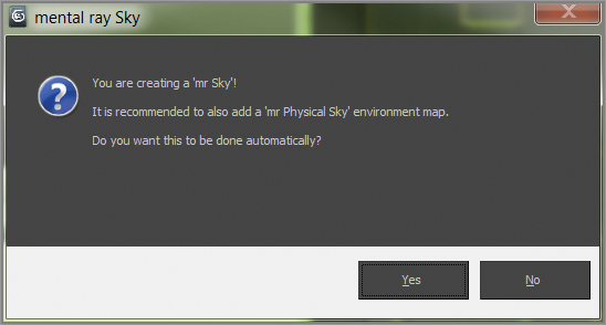
5. With the light still selected, open the Modify panel and in the Daylight Parameters rollout, change the drop-down menus under both the Sunlight and Skylight parameters to mr Sun and mr Sky, respectively. When you change the Skylight parameter, a mental ray warning will appear asking if you want to place an mr Physical Sky environment map in your scene. Click Yes, as shown in
Figure 16-24.
6. Also in Daylight Parameters, under Position, select Manual. This will allow you to use the Move tool to move the light to where you want it. The default position represents noon. The lower the light is to the horizon in your scene, the more it will simulate darker skies at sunset. Leave the light in the default position.
7. Select the Chess Set Camera viewport and render. As you can see, it is too dark. You are trying to simulate a sunny day, and beyond the direct light coming through the window, it’s pretty dark, as shown in
Figure 16-25.
A good tool to use in this situation is mr Sky Portal. It gives you an efficient way of using a scene’s existing sky lighting within interior scenes that do not require costly Final Gather or GI, resulting in very long render times. A portal acts just like a mental ray area light. This light gets its brightness and color from the environment already in your scene.
8. In the Menu Bar, choose Create ⇒ Lights ⇒ Photometric Lights ⇒ mr Sky Portal.
9. In the Front viewport, drag an mr Sky Portal so it fits the window size in the wall. Then in a Top viewport, move the mr Sky Portal back so it is aligned with the opening of the window inside the room, as shown in
Figure 16-26. Make sure the arrow is pointing into the room. Render the Camera viewport again. That helps but it is not enough; it is still too dark, so it’s time to play with exposure controls.
10. In the Menu Bar, choose Rendering ⇒ Exposure Control. Click Render Preview.
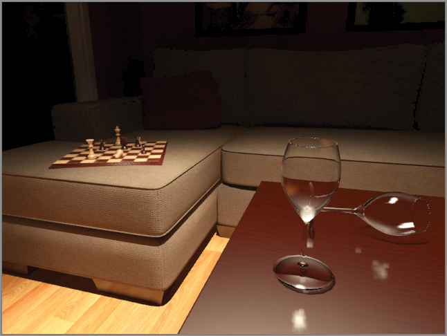
11. In the mr Photographic Exposure Control rollout, change Exposure Value (EV) from 15 (the default) to 11, as shown in
Figure 16-27. You should see the rendered preview change to show the update. Render the Camera viewport again to see the difference. It looks good but is still a bit dark, so it’s time to add Final Gather bounces.
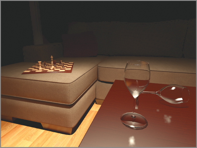
12. In the Rendered Frame Window mini mental ray controls, change FG Bounces to 5. Render the image again; it should look like
Figure 16-28.
That’s it! If you want to play around some more, try moving the light for a more dramatic shadow on the floor. Moving the light can have a dramatic effect on the luminance levels too, so be prepared to edit FG Bounces and Exposure Controls. The last render is shown in Figure 16-29.
HDRI
The high-dynamic-range image (HDRI) is used in CG to create more realistic scenes than the more simplistic lighting models used.
An HDRI is created when several photos at varying exposures are taken of the same subject, ranging from very dark (underexposure) to highlight only the brightest parts of the scene, to very bright (overexposure) to capture the absolute darkest parts of the scene. When these images (typically five or seven images) are compiled into an HDR image, you get a fantastic range of bright to dark for that one subject or environment.
mental ray can create an environment map in your scene to which you assign an image, usually an HDRI. That environment map uses the brightness of its image to cast light in your scene.
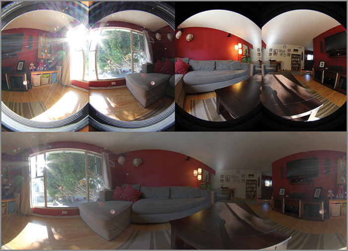
The best type of image to capture for an HDRI is sometimes called a light probe. This is a series of pictures of an environment, such as the living room, using a fish-eye camera lens taken at 90-degree angles on a tripod to capture a full 360-degree panorama. These photos are then stitched together using an image editor like PTgui to create one large panorama showing almost a full 360 degrees of the environment.
Figure 16-31 shows the range of photos from underexposed (dark) to overexposed (bright) that were used to compile this sample HDRI.
In the next exercise, you will use an HDRI that was taken of the real living room used as reference for the scene. See Figure 16-32.
Open the ArchModel_HDRI_start.max file from the Scenes folder of the Arch Model Scene Files project on the book’s web page.
1. When the scene is open, in the Menu Bar, choose Create ⇒ Lights ⇒ Standard Lights ⇒ Skylight. Click anywhere in your scene to create the skylight.
2. Next, load the HDRI file into the environment. Choose Rendering ⇒ Environment. In the Common Parameters rollout in the Environment tab, click the None button under Environment Map. This will bring up the Material/Map browser.
3. Choose Bitmap from the Standard Maps rollout. In the Explore window, navigate to
SceneAssetsImages folder in the Arch Model project, and select the
LivingRoomPanoramic.hdr image file. The HDRI Load Settings dialog box appears; click OK, as shown in
Figure 16-33.
4. The mapping of the HDRI that is loaded in the environment needs to be edited. With the Environment And Effects dialog box still open, open the Slate Material Editor and place the windows side by side. Drag the Environment Map button in the Environment tab to the View Area of the Slate Material Editor. This will open an Instance (Copy) dialog box. Click Instance and then OK to load the HDRI map into the Material Editor. Double-click on the HDRI Map node to load the parameters. In the Coordinates rollout, select Environ and change the Mapping drop-down menu to Spherical Environment, as shown in
Figure 16-34.
5. Select the skylight and in the parameters, under Sky Color, select Use Scene Environment. This will tell the light to refer to the HDRI loaded into the environment for the lighting.
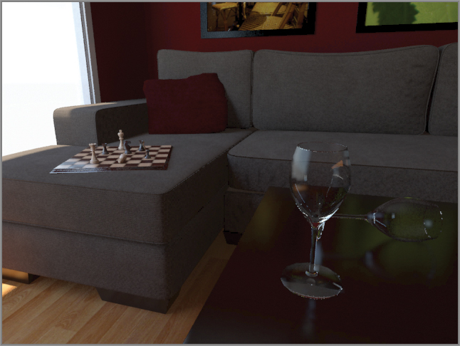
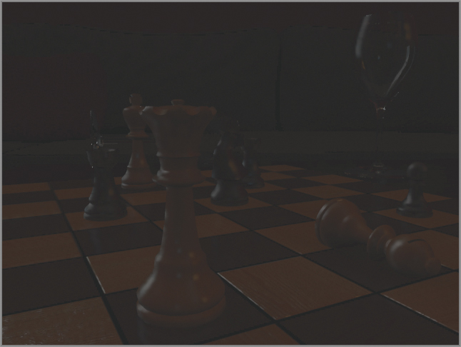
6. Render the Camera viewport, as shown in
Figure 16-35. As you can see, the reflective surfaces look good overall, but the scene appears fairly dull. It certainly doesn’t look like it is daytime, as shown in
Figure 16-35.
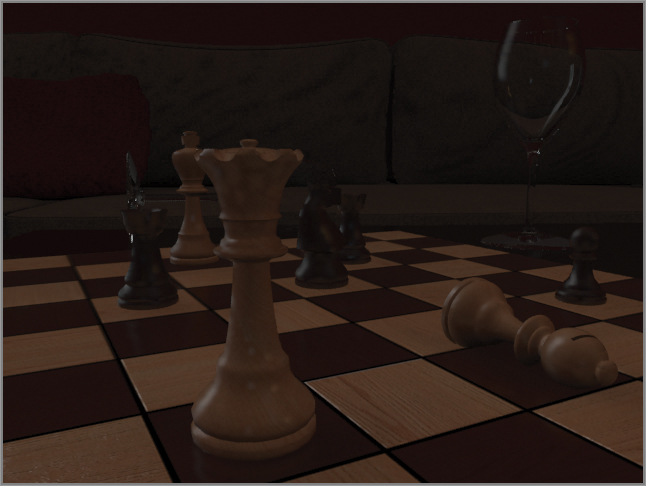
7. The HDRI has created an even light overall but is too dark. Select the Skylight and turn the Multiplier to 8.0. Render the camera again to see the difference, shown in
Figure 16-36.
This improves the look but it is still too dark. The goal for this scene is to create a daylight environment, as if the sun were coming in through the window on the camera’s left. It needs more light—specifically, sunlight! The skylight’s job is to create the indirect illumination. Now, for the sun. With the Daylight system, the scene had both direct and indirect illumination, but the Daylight system doesn’t work with HDRI, so you need another way to create sunlight for this scene. For the sun, you can use almost any light that can be directed. For this exercise, use the mr Area Spot. These lights work well with mental ray and have parameters very similar to any standard lights. Shadows are turned on and set to Raytraced by default.
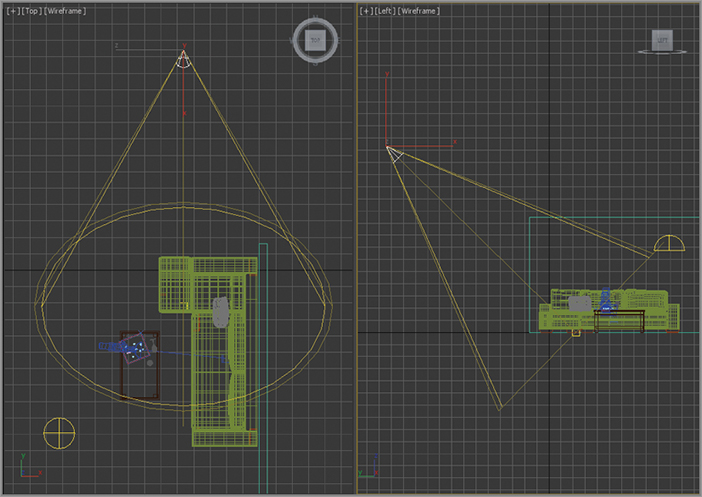
8. In the Menu Bar, select Create ⇒ Lights ⇒ Standard Lights ⇒ mr Area Spot. To create the light in the viewport, start in the Top viewport and drag from outside the window toward the coffee table; then switch to the Left viewport and move the light up, as shown in
Figure 16-37.
9. In the Intensity/Color/Attenuation rollout, change the Multiplier to 1.6.
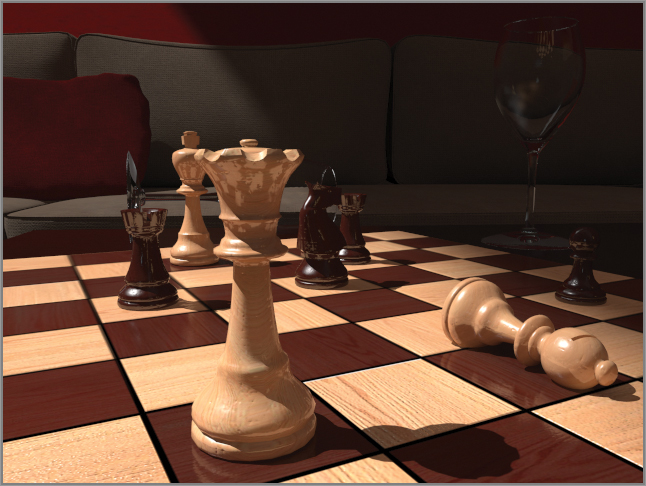
10. Select the mr Area Spot and in the Spotlight parameters, change the shape of the cone to Rectangle, as shown in
Figure 16-38, and then move the target on the light so that the edge of the light is partially on the chess set. This will create an indoor look in a scene that has no walls, ceiling, or floors. Experiment with the light’s location until you get a look similar to the render in
Figure 16-39.
With the still life example, as shown in Figure 16-39, the HDRI environment map created an overall fill light for the scene, but also acted as a great reflection environment. Adding the extra mr Area Spotlight allowed you to create a sunlight for a key light that gave the scene highlights as well as defined directional shadows. HDRI environment maps are very good ways to insert complex lighting scenarios, but are often augmented with standard or photometric lights to bring out the subject of the scene.
The Essentials and Beyond
In this chapter, you learned the basics of rendering with mental ray in the 3ds Max 2012 program. You saw the quality settings and how they could help you with better renders. Finding the right balance of settings for a clean render is an art all to itself. You also started lighting with Final Gather and then learned how HDRI can be useful for lighting.
Additional Exercises
- Create new objects for the scene to which chrome and glass materials can be applied, and then play with rendering the scene to make these objects look photo-real.
- Experiment with different Final Gather settings to get the best look for the least render time in the chess set example.
- Try creating an outdoor scene and use the Daylight System to light.
- Light the outdoor scene using HDRI techniques. The HDR image used for this exercise won’t work well for that outside scene, but you can search online for copyright-free downloadable HDRI images. They may not be free, but making a small investment in a few images would benefit your experience. There are many websites that offer inexpensive packages of themed HDRIs.