Chapter 12
Character Studio: Rigging
At one time or another, almost everyone in the 3D community wants to animate a character. This chapter examines the 3ds Max® 2013 toolsets used in the process of setting up for character animation using Character Studio, a full-featured package incorporated into the 3ds Max software that is used mostly for animating bipedal characters, including humans, aliens, robots, and anything else that walks on two feet—though you can have characters with more than two feet in certain situations.
Topics in this chapter include the following:
- Character Studio workflow
- Associating a biped with the soldier model
Character Studio Workflow
Character Studio is a system built into the 3ds Max program to help automate the creation and animation of a character, who may or may not be exactly a biped (two-footed creature). Character Studio consists of three basic components: the Biped system, the Physique and Skin modifiers, and the Crowd system. Biped and Physique are used to pose and animate a single character, and the Crowd system is used to assign similar movements and behaviors to multiple objects in your 3ds Max scene. This chapter covers the Biped and Physique features; the Crowd system is beyond the scope of this book.
The first step in the Character Studio workflow is to build or acquire a suitable character model. The second step is to skin (bind) the character model to the skeleton so the animation drives the model properly.
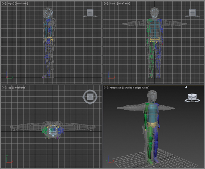
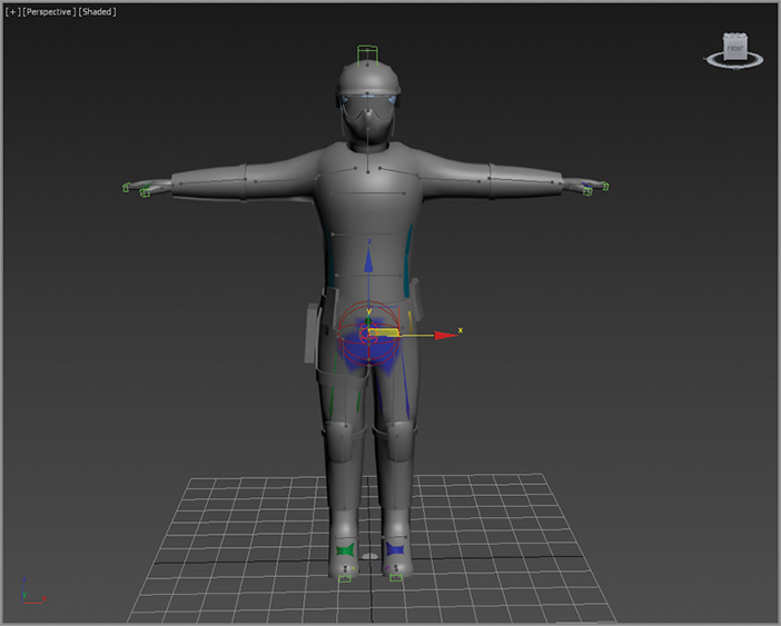
Models should typically be in the reference position known as the “da Vinci pose,” where the feet are shoulder width apart and the arms are extended to the sides with the palms down, as shown in Figure 12-1. This allows the animator to observe all of the model’s features, unobstructed by the model itself, in at least two viewports.
In 3ds Max parlance, a biped is a predefined, initially humanoid structure. It is important to understand that you animate the biped that is associated with your model and not the model itself. Once the model is bound to the skeleton, the biped structure drives the model. You use the Skin modifier to create that relationship between the skeleton and the model.
General Workflow
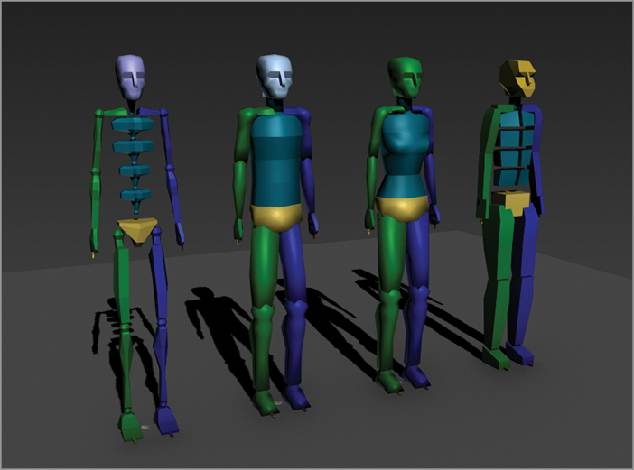
There are four different bipeds you can choose from: the Skeleton, Male, Female, and Classic biped (see Figure 12-2). They all consist of legs, feet, toes, arms, hands, fingers, pelvis, spine, neck, and head. After your model is ready, you will create a biped and, using its parameters and the Scale transform, fit the biped closely to the model. The better the biped-to-model relationship, the easier the animation will be.
Once the biped is fit snugly to the model, you select all the components of the model, not the biped skeleton, and apply the Skin modifier in a process often referred to as skinning. It may take a while to properly test and refine the relationship between the model and the biped to get it to an acceptable level.
Bones and Skin
The Bones system has capabilities similar to those found in Character Studio. Bones is a series of linked, hierarchical components that are used to control the displacement of a model similar to the Biped method. The Bones system requires a more tedious setup process to create a skeleton than the Biped method and is not covered.
The final step is animating your character. You can accomplish this by adding to the biped any combination of default walk, run, and jump cycles included with Character Studio, and then applying any freeform animation to the character, and finally refining the animation keyframes in the Dope Sheet. Don’t expect the default walk, run, and jump cycles to create realistic motion, though. They are just starting points and must be tweaked to achieve acceptable movements.
The best way to start is to jump in and examine the tools available. In the next section, you will work with a biped and adjust the parameters and components to modify it.
Associating a Biped with the Soldier Model
The purpose of a biped is to be the portal through which you add animation to your model, rather than animating the model itself using direct vertex manipulation or deforming modifiers. Any motion assigned to a biped is passed through it to the nearest vertices of the associated model, essentially driving the surfaces of the model. For this reason, it is important that the biped fit as closely as possible to the model.
Creating and Modifying the Biped
In the following steps, you’ll create and adjust a biped to fit to a character model. Set your project to the Soldier project available for download from this book’s web page at www.sybex.com/go/3dsmax2013essentials. You can then open the CSSoldier01.max file from the Scenes folder of the Soldier project. It contains a completed soldier model in the reference position. Be sure to set the project folder to the root folder for the CSSoldier project.
With the soldier model file open, set the viewport rendering type to Edged faces (F4), select the character, and use Alt+X to make the model see-through. Also, right-click in a viewport and choose Freeze Selection. This will prevent you from inadvertently selecting the soldier instead of the biped.
Viewing Frozen Objects
If your background color is similar to the default shade of gray used to depict frozen objects, the model may seem to disappear against the background. There are several solutions to this situation:
- You can go to Object Properties, turn off Show Frozen As Gray, turn on See-Through, and set all viewports to Realistic or Shaded mode.
- You can change the shaded color in the Customize User Interface dialog box (Customize ⇒ Customize User Interface ⇒ Colors).
- You can change the viewport background color in the Customize User Interface dialog box (Customize ⇒ Customize User Interface ⇒ Colors).
Follow these steps to create and adjust a biped:
1. From the Command panel, select Create ⇒ Systems (

) ⇒ Biped. When you click on Biped, the parameters will appear below. Go to Body Type, and from the drop-down menu choose Male.
2. In the Perspective viewport, click at the soldier’s feet and drag to create the biped. The first click sets the insertion point. Dragging defines the height of the biped system and defines all of the components. All of the biped’s components are sized relative to the biped’s Height parameter.
3. Create a biped with a height about the same as the soldier’s. This will size most of the biped’s parts similar to those of the soldier, as shown in
Figure 12-3.
Click any part of your biped to select it. Bipeds react differently than other objects. Selecting any single component of the biped opens the entire Biped object for editing.
4. With the biped still selected, click the Motion tab (

) of the Command panel and enter Figure mode, as shown in
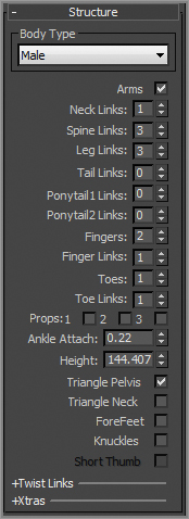
Figure 12-4. Changes to the biped’s features or pose must be made in Figure mode to be retained by the system. Then in the Structure rollout, change the parameters to match
Figure 12-5. The number of spine links should be set to 3. Change the number of toes to 1, and toe links to 2. Because the soldier is wearing boots, a single, wide toe will suffice. Change the Fingers to 2 because with mittens you only need one finger and a thumb.
5. Use the Body Vertical and Body Horizontal buttons in the Track Selection rollout and the Move Transform gizmo to position the biped’s pelvis in the same location as the model’s pelvis, as shown in
Figure 12-6. With the pelvis located properly, scaling the legs or spine to match the model’s proportions will be much easier. Check to make sure the location is correct in all of the viewports.
There are two important factors when creating a rig. The first is to place the joints accurately at the 3d mesh’s joints. The other is to modify only one side of the model, and then use mirroring to copy to the other side.
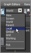
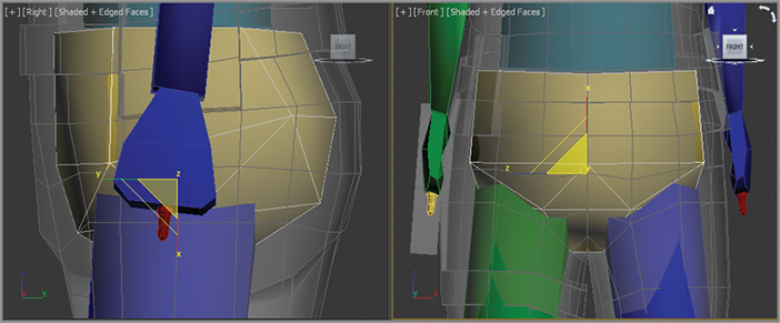
6. Select Scale in the main toolbar; make sure the coordinate system is set to Local, as shown in
Figure 12-7. In the Front viewport, select the pelvis and scale its width so that the biped’s legs fit inside the soldier’s legs. Scale the pelvis in the Right viewport so that it roughly encompasses the soldier’s lower region, as shown in
Figure 12-8.
7. Select the biped’s left thigh, and then scale it along the X-axis until the knee aligns with the soldier’s knee. Scale it on the Y- and Z-axes until it is similar in size to the soldier’s thigh.
8. Select the biped’s left calf. In the Right viewport, rotate the calf to match the model and then scale it on the X-axis until the biped’s ankle matches the soldier’s ankle. You may need to select the left foot and use the Move transform, in the Front viewport, to orient the calf to the model. Scale the calf to match the proportions of the soldier’s calf.
9. Continue working down the leg by scaling the biped’s foot to match the soldier’s. Be sure to check the orientation of the foot in the Top viewport.
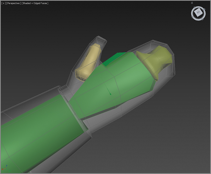
10. Scale and move the biped’s toe to match the model’s boot. Be sure to scale the toe links on the Z-axis, as shown in
Figure 12-9.
11. Double-click the left upper leg to select it and all of the objects below it in the hierarchy, from the thigh down to the toe.
12. In the Biped parameters, open the Copy/Paste rollout.
13. Postures must be saved as collections prior to being pasted. Click the Create Collection button, as shown in
Figure 12-10, and then rename the collection from the default Col01 to Left Leg
.
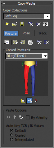
14. Click the Copy Posture button just below the Posture button to copy the selected posture to the Clipboard. A preview of the copied posture will appear in the Copied Postures area of the Command panel, as shown in
Figure 12-11.
15. Click the Paste Posture Opposite button (

). The size, scale, and orientation of the selected objects will be applied to the reciprocal objects on the opposite side of the biped.
Adjusting the Torso and Arms
Similar to the method used to adjust the legs, you will use the Scale and Rotate transforms to fit the biped to the model. The locations of the arms rely on the scale of the spine links. You can continue with your file from the previous exercise or open CSSoldier02.max from the Scenes folder of the Soldier project available on the book’s web page. Just make sure your project is set to the Soldier project.
1. In your scene (or the one from the web page), select the biped and then access Figure mode if needed.
2. To add to the selection without losing the previous one, Ctrl+click to select each of the spine links in turn, and then rotate and scale them to fit the soldier’s torso. Only the lowest spine link can be moved, and this will move all of the links above it as well. Each spine link should be scaled up slightly on the X- and Y-axes to move the biped’s clavicles to match the model’s, as shown in
Figure 12-12. (For this image only, the arms have been hidden so the placement of the clavicles can be seen clearly.)
3. Move, rotate, and scale the left clavicle as required, placing the biped’s shoulder joint in the proper location.
4. Scale and rotate the left upper arm and left forearm using the same techniques you used to adjust the biped’s legs to fit the arm with the model. Pay close attention to the placement of the elbow and wrist joint, as shown in Figure
12-13
5. Scale and rotate the left hand as required to fit the model.
Once the fingers have been adjusted, you cannot go back and change the number of fingers or finger links. If you do, all modifications to the fingers will be lost.
6. The hands need only two fingers (the second finger is actually the thumb) and two links each. Adjust the biped’s fingers to match the model’s fingers, as shown in
Figure 12-14. This can be one of the most tedious tasks in character animation, depending on the complexity and orientation of the model’s fingers. Take your time and get it right. (Would you rather do it right or do it over?)
7. When you are done, paste the posture to the right side of the biped and make any required changes.
Adjusting the Neck and Head
The neck and head will seem easy to adjust when compared to the hands. You need to make sure the neck link fill the soldier’s neck area, and scale the head to fit. Follow along here:
1. In the Structure rollout, increase the number of neck links to 2.
2. Move, scale, and rotate the neck links to match the proportions of the model’s neck.
3. Move and scale the head to the approximate size of the soldier’s head, as shown in
Figure 12-15.
That’s it. The biped has been created and adjusted to fit the 3D model, and half the battle is over. Next, you will tie the biped to the model and make adjustments to the skinning process. Now would be a good time to save your work and take a break.
Applying the Skin Modifier
The Skin modifier is the tool used to skin the 3D model to the biped so that all of the biped’s animation is passed through to the model. It’s important to remember that the modifier is applied to the model and not to the biped. Continue with the previous exercises file or open CSSoldier03.max from the Scenes folder of the Soldier project on the book’s web page to follow these steps:
1. Right-click in any viewport and select Unfreeze All from the Quad menu to unfreeze the soldier model. Then select the Soldier and use Alt+X to exit See-Through mode and turn off Edged Faces (F4).
2. In the Modify panel, expand the modifier list and select the Skin modifier.
3. In the Skin parameters, choose the Bones: Add button and load all bones. Be careful not to add non-Bones objects (in the scene from the web page, you will see a few lights in the list; do not select them).
Testing the Model
The most time-consuming part of the process is complete. You have created a biped and adjusted all of its component parts to fit your model. The next step is to add animation that will allow you to test the skinning once it has been applied.
Before we get into fixing the skin, you need to add a little extra animation. Select the soldier model and right-click in the viewport to get the Quad menu. Choose Hide Selected.
1. To unfreeze the soldier model, right-click in any viewport and select Unfreeze All from the Quad menu. Select the model, right-click again, and from the Quad menu choose Hide Selected.
2. Move the timeline to frame 0. Turn on the Auto Key button (

) below the timeline.
3. Select the entire biped. The best way to do this is to select the Select from Scene tool from the main toolbar (

); and from the dialog, select all the Biped objects and press OK. Go to the Motion panel (
), and click the Figure Mode button (

) to exit. You cannot animate a biped in Figure mode.
4. Select the Move tool and move the biped just a bit. The purpose of this is to create a keyframe of this original pose, so that when you add animation this pose won’t be lost. The biped should still be in the same position as before—just give the Move tool a wiggle.
5. Select the right upper arm and then Ctrl+click the left upper arm on the biped and then set the Coordinate System menu to Local, as shown earlier in
Figure 12-7.
6. Move the timeline to frame 15, rotate the arms –55 degrees on the Z-axis (the blue wire in the rotate gizmo).
7. Now select the right and left lower arms on the biped and rotate –55 degrees on the Z-axis.
8. Move the timeline to frame 30 and select the upper arms again, but this time rotate 45 degrees on the Y-axis (green wire).
9. Now move to frame 50 and select the lower arms and upper arms. In the timeline Shift+click on the keyframe at frame 0, and then move it to frame 50. This copies the keyframe at frame 0 to frame 50.
Using the same technique, add animation to the legs, chest, and head. The animation does not have to be elaborate. The purpose of the animation is to test the skinning when applied to the model. When you are finished, turn off the AutoKey button and Unhide the soldier and play the animation. Most likely you will see some problem with the mesh—mostly around the feet, upper arms, and groin, as shown in
Figure 12-16.
Tweaking the Skin Modifier
Each element in the biped has an area of influence, called an envelope. It determines which parts of the model it affects. The biped’s left foot, for instance, should control the movement of only the model’s left foot and the lower part of the ankle. In this case, the envelopes extend to affect some of the vertices on the opposite side. You can continue with your file from the previous exercise or open CSSoldier04.max from the Scenes folder of the Soldier project available on the book’s web page.
To fix the envelopes, follow this procedure:
1. Select the soldier model and in the Skin parameters, select the Edit Envelopes button.
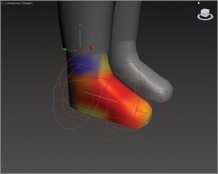
The model turns gray except for a color gradient around the pelvis. The gradient shows how heavily weighted vertices on your mesh are to a given envelope, as shown in
Figure 12-17. The Biped bone is represented in the viewport as a straight line with vertices at either end. Envelopes are represented by two concentric capsule-shaped volumes; vertices within the inner volume are fully affected by that bone, and then the weighting falls off increasingly for vertices that lie outside the inner volume and inside the outer volume. The weight values appear as a colored gradient with red representing higher weights, decreasing to orange, yellow, green, and then blue for the lowest values.
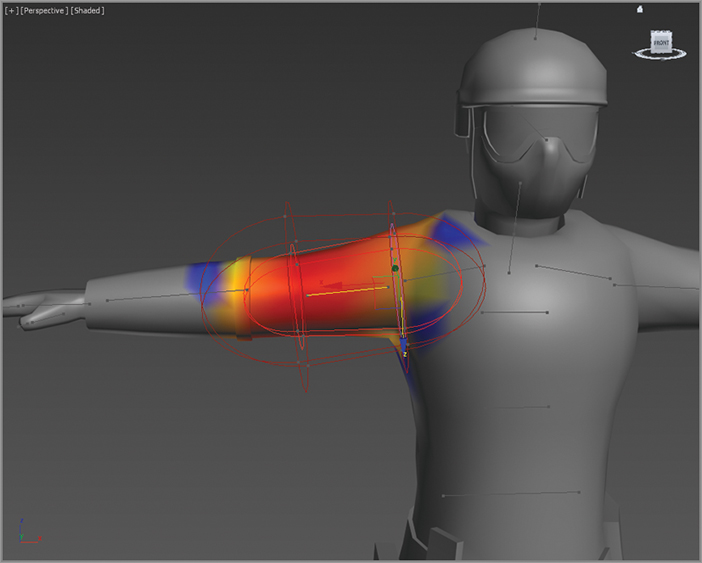
2. Select the Bip001 R UpperArm object. You can select the object from the name list in the Skin parameters or just click on the representation of the bone on the model. Select the vertices at the end of the bone and move in to make the envelope smaller, as shown in
Figure 12-18.
As the vertex moves, the gradient that represents the influence changes so the yellow-red color is moving up the arm. You want the influence to be on the upper arm only. Repeat the same on the other side of the bone, bringing it in toward the center of the bone.
3. Select and move the points on the outer envelope and move them in on both sides of the bone, as shown in
Figure 12-19. The final result is shown in
Figure 12-20.
Move to frame 30 in the animation; in this frame you can really see the problem with the arm. Even though you edited the envelope for the upper arm, you can’t see any improvement in the deformity. The previous exercise showed how to edit the envelope; now let’s figure out where the trouble really lies with the upper arm. There is one bone that is affecting the upper arm: Bip001 Spine 2 bone.
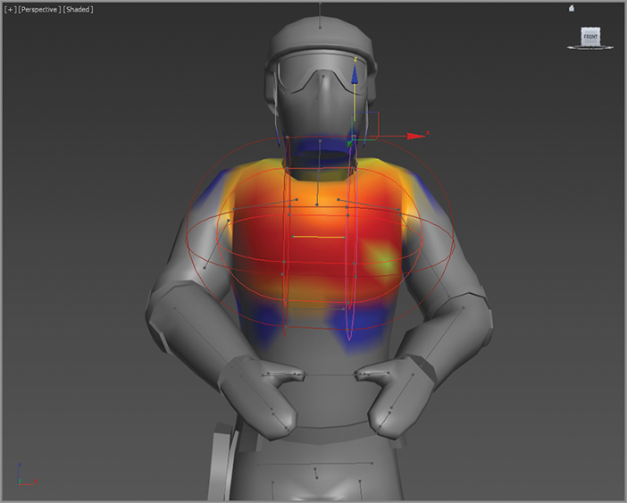
4. Select the Spine 2 bone. This bone’s envelope is huge! It is influencing almost the whole upper body. Select a vertex on either end of the bone and move it in; immediately you will see the arms reacting. Now scale down the size of the outer envelope so that the gradient has some yellow on the inside and blue between the capsules, as shown in
Figure 12-21. Now select and edit the remaining two Spine bones.
The feet are the next area with problems and a bit more of a challenge to fix. Move to frame 88 in the animation. This frame shows that the part of the mesh on the inside of the feet is getting pulled.
5. Select the Bip001. Move the Time slider back to frame 1; it will be easier to edit the envelope when the foot isn’t so distorted.
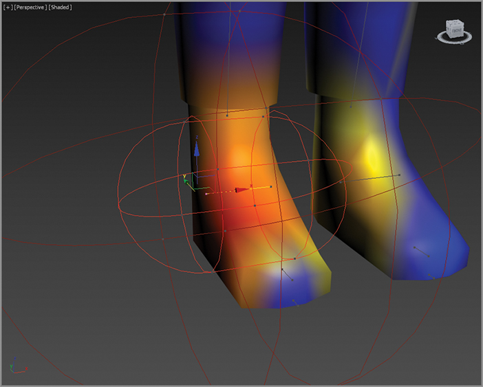
6. Look closely at the bone. As shown in
Figure 12-22, the bone is actually sideways. Move the points on the bone so they run from the toe to the heel. Then edit the envelopes so that the gradients are isolated on the foot, as shown in
Figure 12-23.
Continue editing the bones and envelopes for the right side and middle of the model. Once you are finished, the next step is to mirror the results to the left side of the body.
7. Select the Foot bone. In the Mirror parameters of the Skin modifier, select the Mirror Mode button. Then set the Mirror Offset to –8.3, as shown in
Figure 12-24. This splits the body into half, blue side and green side. Then click on the Paste Blue to Green Bones button (

).
In the Skin parameters, select the Edit Envelope button to exit. Play the animation again and pay attention to any areas where you see parts of the mesh pulling or distorting. Go back to that area’s envelope and edit until you are happy with the results.
Weighting the Accessories
Now let’s improve the skinning on the accessories, the gun holster on the right side belt of the soldier, by adjusting the weight setting for the vertices. This technique is another way of editing the skinning on a character. You can choose to use the vertex weighting technique in conjunction with editing envelopes or use it exclusively. You can continue with your file from the previous exercise or open CSSoldier05.max from the Scenes folder of the Soldier project available on the book’s web page.
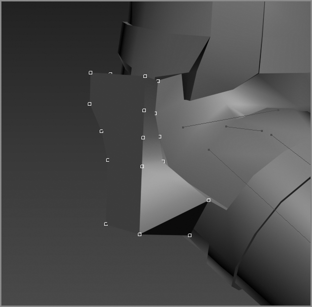
1. In the Skin Parameters rollout’s Select section, uncheck Envelopes and Cross Sections. Check Vertices and Select Element, as shown in
Figure 12-25. You are selecting elements because you are working with the accessories that are individual objects attached to the overall soldier model.
2. Drag a selection box around the gun holster; the selected vertices appear as white hollow boxes. If any other element is selected, then Alt+click or Alt+drag to deselect those vertices.
3. In the Weight Properties rollout, click on the Weight Table button; this will open the Weight Table dialog box.
4. In the Weight Table dialog box, in the Options menu, choose Show Affected Bones. At the bottom of the dialog box is a drop-down menu; choose Selected Vertices.
5. On the left of the Weight Table dialog box under Vertex ID, drag from the top of the list down to the bottom to highlight all the vertices in the list. Then highlight at the top of the dialog box Bip001 Pelvis. Click on one of the numbers in the list below Bip001 Pelvis, type in 1, and then press Enter. All the numbers in the list change to 1, while the numbers in the other lists change to 0, as shown in
Figure 12-27. You just put all the weight of the gun holster on the pelvis, and removed it from the thigh and spine.
Now if you play the animation, you will see the gun holster looks stiff and doesn’t move with the leg. Continue using the Skin Weight Table to edit the various soldier accessories, including the face mask, belt pouches, and anything that looks deformed and shouldn’t.
Testing the Model
The most time-consuming part of the process is complete. You have created a biped, adjusted all of its component parts to fit your model, and applied the Skin modifier to link the model to the biped. Let’s really put the rig to the test and add some animation. Continue with your file from the previous exercise or open CSSoldier06.max from the Scenes folder of the Soldier project available on the book’s web page. This file has the completed rig with all the animation deleted. These were done by selecting all the Biped bones, and dragging a selection around the keyframes and deleting them in the timeline.
1. Select any element of the biped and click the Motion tab of the Command panel.
2. Enter Footstep mode (

).
The rollouts change to display the tools for adding and controlling a biped’s motion. The Footstep mode and Figure mode are exclusive; you cannot be in both modes at the same time.
3. In the Footstep Creation rollout, make sure that the walk gait is selected and then click the Create Multiple Footsteps button (

) to open the Create Multiple Footsteps dialog box.
4. In the dialog box that appears, you will assign Footstep properties for the number of steps you want, the width and length of each step, and which foot to step with first. Set the number of footsteps to 8, leave the other parameters at their default values, and click OK.
5. Zoom out in the Perspective viewport to see the footsteps you just created. Look at the Time slider, and note that the scene now ends at frame 123; that’s 23 more frames than the 100 frames the scene had at the beginning of this chapter. The 3ds Max software recognized that it would take the biped 123 frames, or just over 4 seconds, to move through the eight steps that it was given.
6. Click the Play Animation button in the Playback Controls area. What happens? Nothing. The biped must be told explicitly to create animation keys for the steps that you have just added to the scene. Drag the Time slider back to frame 0.
7. In the Footstep Operations rollout in the Command panel, click the Create Keys For Inactive Footsteps button (

). The biped will drop its arms and prepare to walk through the footsteps that are now associated with it.
8. Click the Play Animation button again. This time the biped walks through the footsteps with its arms swinging and its hips swaying back and forth.
Controlling the View
Now the problem is that if you zoom in on the biped and play the animation, it walks off the screen so you cannot see the end of the walk cycle. What good is that? Motion cycles can be very linear and difficult to track, so Character Studio contains the In Place mode to follow a biped’s animation. In the In Place mode, the biped will appear to stay in place while the scene moves around it in relation. The In Place mode cannot be used in a Camera viewport, however.
1. Go to frame 0 and then zoom in on the biped in the Perspective viewport.
2. At the bottom of the Biped rollout, click the Modes and Display text with the plus sign to the left of it. This is a small rollout located inside of another rollout that expands to show additional display-related tools.
3. In the Modes And Display rollout, click the In Place Mode button, as shown in
Figure 12-28.
4. Click the Play Animation button again. This time the biped will appear to be walking in place while the footsteps move underneath it. Stop the animation playback when you’re ready.
Using the In Place mode helps you work out the way a character moves without having to navigate throughout 3D space with your viewport, so you won’t need to hunt down your biped. The In Place mode is great for tweaking your animation cycle because the viewport moves with the character in 3D space and you can concentrate on how its body is moving.
5. Exit Footstep mode, and then select the entire soldier biped by double-clicking on the Bip001.
6. Right-click in any viewport and choose Hide Selection from the Quad menu to hide the biped and obtain an unobstructed view of the model.
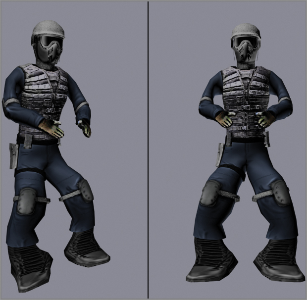
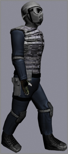
7. Click the Play Animation button. Your soldier will walk through the scene. It should be similar to the rendered soldier shown in
Figure 12-29.
Skinning a character is a detail-oriented task, and it requires lots of experimentation and trial-and-error—and patience. Character Studio is a complete character-animation package, and we’ve barely scratched the surface here. There are tools for saving biped configurations and sequences of animation. You can mix animation sequences from different files to create an entirely new motion. When the model does not skin as well as you need, you can use envelopes to refine the skinning process further, define vertices to be excluded from a specific Biped object’s influence, or include bulge conditions to define the model’s behavior depending on the angle between subsequent biped elements.
The list goes on, but the good news is that the Character Studio tutorials and help system that ship with the 3ds Max program are very thorough, and you should find the information there to expand your skills once you have a solid footing with the basics. It’s important to realize that animation requires nuance, and the best animation with the simplest rig and setup will beat a mediocre animation created with a more wonderful, complicated, and ingenious setup.
The Essentials and Beyond
This chapter introduced you to the basics of Character Studio and Biped setup for the soldier character. You used Skin to apply the Biped setup to the geometry of the soldier and adjusted the envelopes for the best animation results.
Additional Exercises
- Try adjusting the proportions of the soldier model to create a new character design and adjust the biped accordingly.
- Try adding a tail to the biped for an interesting creature.