
Chapter 10
Introduction to Materials: Interiors and Furniture
A material defines an object’s look—its color, tactile texture, transparency, luminescence, glow, and so on. Mapping is the term used to describe how the materials are wrapped or projected onto the geometry (for example, adding wood grain to a wooden object). After you create your objects, the Autodesk® 3ds Max® program assigns a simple color to them, as you’ve already seen.
You define a material with the 3ds Max software by setting values for its parameters or by applying textures or maps. These parameters define the way an object will look when rendered. Much of an object’s appearance when rendered also depends on the lighting. In this chapter and in Chapter 14, “Introduction to Lighting: Interior Lighting,” you will discover that materials and lights work closely together.
Topics in this chapter include the following:
- Slate Material Editor
- Standard material types
- mental ray material types
- Shaders
- Mapping the couch and chair
- Mapping the windows and doors
The Slate Material Editor
The Material Editor is the central place where you do all of your material creation and editing. You can assign materials to any number of objects, as well as have multiple materials assigned to different parts of the same object.
The 3ds Max® 2013 program has two interfaces to the Material Editor: the Slate Material Editor (or Slate) and the Compact Material Editor.
The Slate Material Editor is the interface you will use in this book: it is far superior to the compact version and is especially nice when you are first learning mapping because you can see the material structure, as shown in Figure 10-1.
Figure 10-1: The Slate Material Editor

You can access the Material Editor by choosing Rendering ⇒ Material Editor ⇒ Slate Material Editor. There is also an icon for it on the main toolbar (![]() ), and the keyboard shortcut to open the Material Editor is the M key. The Slate Material Editor is the default Material Editor, but if it opens as the Compact Material Editor, you can switch it in the menu bar at the top of the Material Editor by selecting Modes ⇒ Slate Material Editor. The Slate Material Editor has an interface that uses nodes and wiring to display the structure of materials. It has a simple and elegant layout with the Material/Map browser on the left for choosing material and map types. The center area is the Active View area where you build materials by connecting maps or controllers to material components. The area on the right is the Parameter Editor; within that area is a Navigator for moving within the Active View area.
), and the keyboard shortcut to open the Material Editor is the M key. The Slate Material Editor is the default Material Editor, but if it opens as the Compact Material Editor, you can switch it in the menu bar at the top of the Material Editor by selecting Modes ⇒ Slate Material Editor. The Slate Material Editor has an interface that uses nodes and wiring to display the structure of materials. It has a simple and elegant layout with the Material/Map browser on the left for choosing material and map types. The center area is the Active View area where you build materials by connecting maps or controllers to material components. The area on the right is the Parameter Editor; within that area is a Navigator for moving within the Active View area.
Material Types
Different materials have different uses. The Standard material is fine for most uses. However, when you require a more complex material, you can change the material type to one that will fit your needs. To change a material type in the Slate Material Editor, just choose from the list under Materials in the Material/Map browser. You should see the rollout for Standard. If you are using the mental ray renderer, you will also see a rollout for mental ray and MetaSL. As you can see, the list is extensive; there are not enough pages in this book to cover the multitude of material types so we will touch on some of the best for an introduction. You will also see some examples using the Slate Material Editor.
Standard Materials
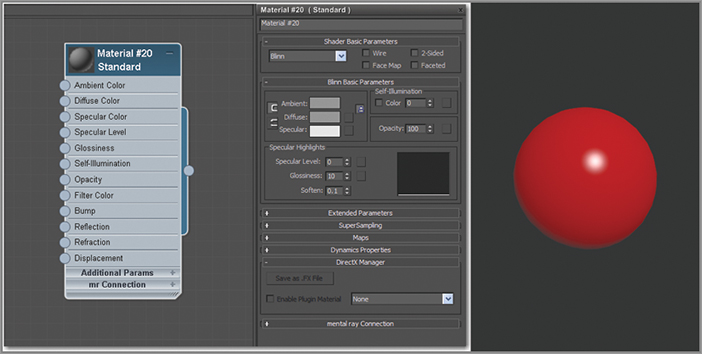
Standard materials typically use a four-color model to simulate a surface of a “single” color reflecting many colors. The four colors are known as the material’s color components. Ambient color appears where the surface is in shadow, diffuse color appears where light falls directly on the surface, specular color appears in highlights, and filter color appears as light shining through an object. Along with the color components, there are parameters that control highlights, transparency, and self-illumination. Some of these parameters are different depending on the shader you are using. With the Standard material you can imitate just about any surface type you can imagine, as shown in Figure 10-2.
Figure 10-2: The Standard Material type shown in Slate Material Editor
Compound Materials
Compound materials combine two or more submaterials for a variegated look, especially when used with maps. Compound materials are similar to compositor maps, but they exist at the material level, as shown in Figure 10-3. You load or create compound materials using the Material/Map browser.
Figure 10-3: Double-Sided material is one of the many Compound materials.
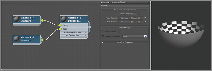
Figure 10-4: The Ink ’n Paint material is shown with parameters in the Slate Material Editor.

mental ray Material Types
The 3ds Max program comes with several materials created specifically for use with the mental ray renderer. These materials are visible in the Material/Map browser when mental ray is the active renderer. For the sake of time and space we are only going to cover one here.
Shaders
The way light reflects from a surface defines that surface to your eye. With the 3ds Max program, you can control what kind of surface you work with by changing the shader type for a material. In either the Compact or Slate Material Editor, you will find the shader type in the material parameters in the Shader Basic Parameters. This option will let you mimic different types of surfaces, such as dull wood, shiny paint, or metal. The following descriptions outline the differences in how the shader types react to light, as shown in Figure 10-5.
Figure 10-5: Shader types shown on a rendered sphere

Mapping the Couch and Chair
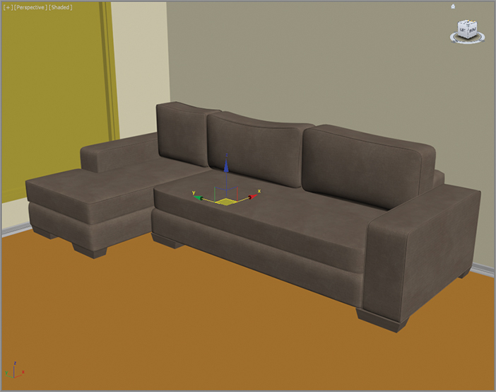
Now let’s dive into creating material for the couch we modeled in Chapter 4, “Modeling in 3ds Max: Architectural Model Part II,” to get it ready for lighting and rendering in later chapters.
Study the full-color image of the couch shown in Chapter 4 in Figure 4-1. That will give you an idea of how the couch is to be textured. The couch’s material is basically all the same; once you create the material, it can be added to all the couch pieces.
Creating a Standard Material
Start by opening your final couch model from your work in Chapter 4, or open the ArchModel_furniture_01.max file from the Scenes folder of the Arch Model project downloaded from the book’s web page at www.sybex.com/go/3dsmax2013essentials. This file has the room with the spline chair and couch set up. When you open this file, select the couch and press Alt+Q to enter Isolate Selection mode.
Applying the Material to the Couch
In the scene, select the couch. In Chapter 4, when the couch was merged into the room file, it was grouped. You can add materials to objects that are grouped; it can save time by applying the materials to all the pieces at the same time.
The material may look slightly different in the viewport compared to in the Material Editor thumbnail, as shown in Figure 10-6. The best way to view the material is by rendering the viewport. Select the Perspective viewport and in the main toolbar, click the Render button (![]() ), or press F9 for Render Last. The render looks a bit flat. This is something you can edit by changing the color values until the color looks the way you want. Always judge your colors using the render.
), or press F9 for Render Last. The render looks a bit flat. This is something you can edit by changing the color values until the color looks the way you want. Always judge your colors using the render.
Figure 10-6: Compare the material color in the Material Editor to the viewport.
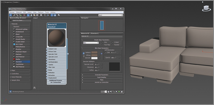
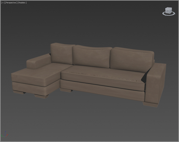
Figure 10-7: The render of the couch with a Standard material applied

Adding a Bitmap
The couch material needs some refinement. It looks flat and too perfect, which in this instance isn’t a good thing. A material with just color is not enough; what is needed is a map. Two map types are available: 2D and 3D. 2D maps are two-dimensional images that are mapped onto the surface of 3D objects; the simplest 2D maps are bitmaps (aka image files). 3D maps are patterns generated procedurally in three dimensions using the 3ds Max software. Using a map to replace the diffuse color is a way to create a more realistic material because you are using actual images. Using maps in other material components can have various effects, such as making a material look bumpy and controlling its transparency.
In the Active view, two additional nodes have been added to the main material node. The green node is the Bitmap node, which holds the fabric image. The yellow node is a Controller node and provides a number of ways to animate the settings of a material or map. Animating material components will not be addressed in this book.
Figure 10-8: The couch with the fabric image applied
Introduction to Mapping Coordinates
An image map is two-dimensional; it has length and width but no depth. 3ds Max geometry, however, extends in all three axes. Mapping coordinates define how and where image maps are projected onto an object’s surfaces and whether the maps are repeated across those surfaces.
Mapping coordinates can be applied to objects in several ways. When primitive objects are created and the Generate Mapping Coords option is checked at the bottom of the Parameters rollout, the appropriate mapping coordinates are created automatically. The next way is by applying a UVW Mapping modifier, which is commonly used to apply and control mapping coordinates. You select the type of mapping projection, regardless of the shape of the object, and then set the amount of tiling in the modifier’s parameters. The mapping coordinates applied through the UVW Mapping modifier override any other mapping coordinates applied to an object, and the Tiling values set for the modifier are multiplied by the Tiling value set in the assigned material.
Using a UVW Mapping Modifier
You are going to use a modifier to replace those coordinates on the geometry. The UVW Mapping modifier allows you to change the bitmap by transforming the UVW Mapping modifier gizmo. In Chapter 4 you grouped the couch when you merged it into the room; for this part of the chapter, you need it to be ungrouped.
Figure 10-9: The Alignment section for the UVW Mapping Modifier parameters

The UVW Mapping modifier has also changed the image on the couch. The size is more consistent throughout the couch, but the size of the fabric texture is too big. Now let’s adjust the UVW Mapping gizmo:
Now that the couch fabric is where it should be, it is time to add the UVW Mapping modifier to the remaining pieces of the couch.
Figure 10-10: The final results of the couch mapping
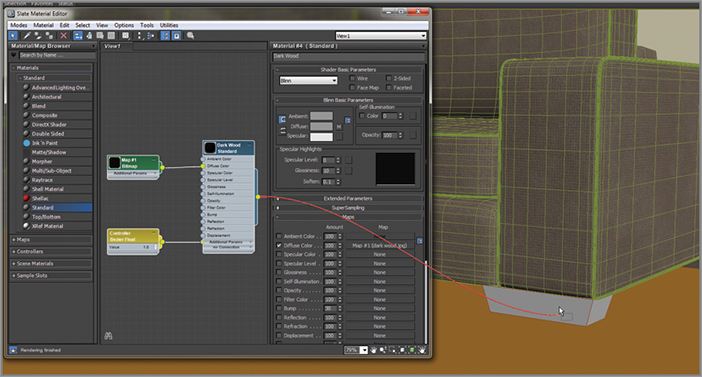
The couch is not finished just yet; look closely at the couch feet. If you compare the current scene couch to the image of the real couch, the feet should be a dark wood, not the fabric that is on them now. Continue with your current file or open ArchModel_furniture_02.max file from the Scenes folder of the Arch Model project downloaded from the book’s web page at www.sybex.com/go/3dsmax2013essentials.
Figure 10-11: Apply the Dark Wood material by clicking and dragging from the nodes output socket to the couch foot.
Applying a Bump Map
You are almost but not totally done with the couch. One important feature of the couch is the bumpiness on the surface of the fabric of the couch, as shown in Figure 10-12. This bumpiness changes all the specular and reflective properties on a surface. Bump mapping is very common in CG. It adds a level of detail to an object fairly easily by creating bumps and grooves in the surface and giving the object a tactile element. Bump mapping uses the intensity values (the brightness values) of an image or procedural map to simulate bumpiness on the surface of the model, without changing the actual topology of the model itself. You can create some surface texture with a bump map; however, you will not be able to create extreme depth in the model. For that, you may want to model the surface depth manually or use displacement mapping instead. To add a bump map to the couch, follow these steps:
Figure 10-12: The couch fabric showing the subtle surface bumpiness

Figure 10-13: The couch fabric without the bump map (left); the couch fabric with the bump map (right)

Applying the Material to the Chair
Mapping the chair is in some ways very much like mapping the couch. Continue with your current file or open the ArchModel_furniture_03.max file from the Scenes folder of the Arch Model project downloaded from the book’s web page at www.sybex.com/go/3dsmax2013essentials. The file has the chair centered in the viewports, and the chairs group is open so you can select the individual pieces. The Cushion material has also been applied using the same techniques outlined in the previous section. If you are continuing with your file, create the Cushion material using the techniques discussed in the previous section. Add the BrownWovenFabric.tif for the Diffuse and the BrownWoven Fabric_bmp.tif as the bump. Set the Bump Amount to 60. When you're mapping images onto a surface, the important thing to remember is to match the scale of the original fabric, as shown in Figure 10-14.
Let’s also create the base material for the chair frame.
Figure 10-14: Compare the real texture on the left to the created material on the right to get it similar.

Applying a Reflection
Reflection occurs when light changes direction as a result of “bouncing off” a surface like a mirror. In the following steps, you will create reflections in the chair’s wood frame.
A reflection creates the illusion of chrome, glass, or metal by applying a map to the geometry so the image looks like a reflection on the surface. A reflect/refract map is a way to provide reflections on a material.
Figure 10-15: The wood texture is applied to the chair frame.
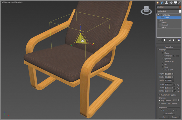
Figure 10-16: Results of adding the reflect/refract map added to the reflection map

Figure 10-17: Final reflections on the chair

Mapping the Window and Doors
The window and doors are special 3D primitive objects. They are a collection of multiple objects attached together: a frame, mullions, and glass. You can edit those objects within the AEC objects parameters. They also give you the ability to add materials to the individual pieces within the attached whole.
Creating a Multi/Sub-Object Material
The Multi/Sub-Object material, which is in the Compound Materials category, lets you assign different materials at the sub-object level of your geometry. In the case of the AEC window, it is already divided into separate sub-object levels so you just have to apply the material and identify the different parts. Continue with your current file or open ArchModel_furniture_04.max file from the Scenes folder of the Arch Model project downloaded from the book’s web page at www.sybex.com/go/3dsmax2013essentials.
Figure 10-18: Multi/Sub-Object node and parameters
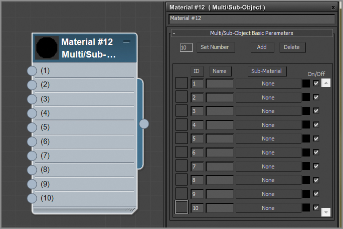
Figure 10-19: Adding a Standard material to the Multi/Sub-Object Material node
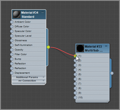
Figure 10-20: Finished MSOM with five Standard materials added
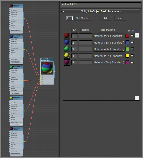
The numbers in the MSOM parameters are material IDs. Most objects do not have material IDs by default. They have to be created by converting the object to an editable polygon and selecting a group of polygons and adding a material to that selected group of polygons. AEC objects like the window and doors already have them assigned; they just have to be identified.
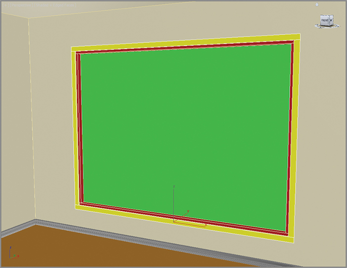
Figure 10-21: The Multi/Sub-Object Material applied to the window object shows the different colors applied to the different parts of the window.
When the scene renders, the Reflection amount will appear to be very high; this is a bit of an illusion because of the black in the background. In Chapter 14, lighting will be covered and this issue will be addressed more thoroughly; but for now, you will just change the background color. In the Rendering menu, choose Environment, click on the color swatch under Background ⇒ Color, and change it to a light gray. Now the reflection looks more appropriate. Eventually, an image of an outdoor scene will be placed behind the glass. For now, let’s continue with the MSOM for the window. Window frames and mullions come in many colors and textures, but for this example you are going to use a shiny, white plastic.
Figure 10-22: Drag from the output socket of the Shiny White Plastic into the input socket of the remaining ID slots of the Multi/Sub-Object material.

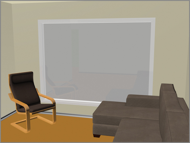
This places a clone of the Shiny White Plastic into the three remaining material slots and completes the Window material, as shown in a render in Figure 10-23.
The same technique used for the window can be used for the doors, but if you want the doors to be just a plain solid color or simple wood, apply a Standard material to the entire Door object. We’ll return to this room in Chapter 14 when we look at lighting. Meanwhile, finish assigning materials to the rest of the scene.
Figure 10-23: The completed window
- Using the collection of images in the Sceneassets/Images Folder of the Arch Model project, add materials to the floor and ceiling.
- Merge in furniture from the Scenes ⇒ Furniture folder from the Arch Model Project. Create materials for these items. Try to match as closely as possible the real furniture in the reference images of the room. These models were built for you to use to practice texturing and lighting.
- Create a MSOM for the walls and use the colors you want. The actual colors can be seen in Figure 3-1 in Chapter 3, “Modeling in 3ds Max: Architectural Model Part I.” Now the walls will take an extra step. The Wall object has IDs because it is an AEC object, but the IDs are not where you want them. You need to a convert the object to an editable polygon.