Chapter 7
Character Poly Modeling: Part I
In games, characters are designed and created cleverly to achieve the best look with the lowest amount of mesh detail to keep the polygon count low. With that in mind, this and the next two chapters introduce you to character modeling, focusing on using the Editable Poly toolset to create a relatively low-polygon-count soldier model suitable for character animation and for use in a game engine (though that topic is not covered in this book). This chapter begins with the basic form of the character first.
Topics in this chapter include the following:
- Setting up the scene
- Creating the soldier
Setting Up the Scene
You can import and use sketches of the character’s front and side as background images as you create the character using the 3ds Max® toolset. Additional sketches of your character from several points of view can be used as quick references to help you target your goal.
High- and Low-Poly Modeling
High-polygon-count models are used when a model’s level of detail needs to be impeccable, such as when the model is used in close-ups. High-polygon models are also used to generate displacement and normal maps to use on lower resolution models. This technique is used to add needed detail without the issues that come with large model sizes.
Low-polygon-count modeling, also called low-poly modeling, refers to a style of modeling that sacrifices some detail in favor of efficient geometry that places a very low load on the system on which it is being created or rendered. The number of triangles needed to consider something low-poly is based on the rendering platform and increases as the technology improves.
Creating Planes and Adding Materials
This exercise begins by creating crossed boxes and applying reference images to them. Set your project to the Soldier project downloaded to your system:
1. In a new scene, go to the Front viewport and create a plane.
2. In the Parameters rollout of the Command panel, set Length to 635 and Width to 622. The units are in inches, which is the 3ds Max default. The size of the image planes in units is the same size as the reference images in pixels. Therefore, when you apply the image to the plane, it will be proportional, maintaining its width and length with no stretching or squeezing of the images.
3. Rename this box Image_Plane_Front.
4. With the plane still selected, go to the Modify tab and in the Parameters rollout set the Length and Width Segs to 1. Then select the Move tool (W) in the main toolbar, and in the Transform type-in areas at the bottom of the user interface, move the plane to these coordinates: 0.0, 80, –5.
5. Click in a blank space in the user interface (UI), and then press Ctrl+ Shift+Z on your keyboard to initiate the shortcut for Zoom Extents All. In the main toolbar, turn on the Angle Snap toggle (

) or press A on your keyboard. Doing so will snap your rotation to every 5 degrees. Select the Rotate tool (E) and hold down the Shift key on the keyboard; then in the Front viewport, rotate the image plane along the Y-axis 90 degrees. Using the Shift key activates the Clone tool, as shown in
Figure 7-1.
6. In the Clone Options dialog box, under Object select Copy; name it Image_Plane_Side and click OK.
7. Switch to the Move tool and move the plane to these coordinates: -82, 0, –5.
Adding the Materials
At this point, the reference materials are texture-mapped onto the planes to provide a reference inside the scene itself while you model the character. Therefore, it’s critical to ensure that the features of the character that appear in both reference images (the front and the side) are at the same height. For instance, the top of the head and the shoulders should be at the same height in both the front and side views to make the modeling process easier.
1. In the Left viewport, press the V key on your keyboard and select Right View from the list. Change the shading in the Right viewport to Consistence Colors (F3).
2. Open an Explorer window and navigate to the
Soldier/sceneassets/images folder on your hard drive from the Soldier project you downloaded from the book’s web page at
www.sybex.com/go/3dsmax2013essentials. Drag
ImagePlane_Front.jpg from the Explorer window to the image plane in the Front viewport.
3. Drag
ImagePlane_Side.jpg onto the image plane in the Right viewport. The image planes should have the two images mapped on them, as shown in
Figure 7-2.
Creating the Soldier
A good practice is to block out the basic form of the character and focus on the size and crucial shapes of the major elements, and then add detail for the finer features. The following exercises describe the steps required to block out the soldier’s major features. Go wild!
Forming the Torso
The basic structure for the torso will begin with a simple box primitive. After converting the box into an editable poly, you will use the Mirror tool on the object so that any manipulations performed on one side are also performed on the other. You will begin forming the basic shape of the torso by moving the editable poly’s vertices and extruding its polygons in the following steps.
Continue with the previous exercise’s scene file, or open the Soldier_V01.max scene file in the Scenes folder of the Soldier project downloaded from this book’s web page.
1. Go to the Shading Viewport Label menu and choose Shaded and then select F4, this will turn on Edged Faces, do this if it isn’t already set that way.
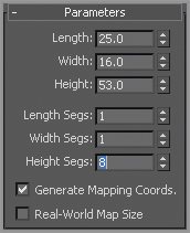
2. Start by creating a box primitive in the Perspective viewport with these parameters: Length:
25, Width:
16, Height:
53, Input Height Segs:
8. Leave the Width and Length Segs at
1, as shown in
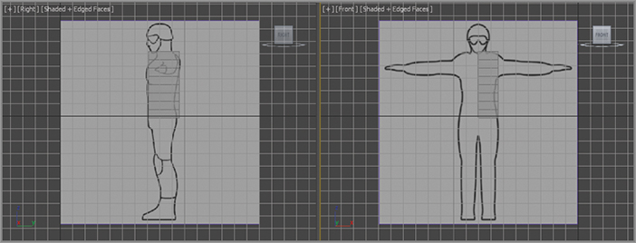
Figure 7-3. This is a starting point for the detail needed to create the form of the body. Position the box as shown in
Figure 7-4. Press Alt+X to make the box see-through. Change the box’s name to Soldier
.
3. In the Graphite Modeling Tools ribbon on the Poly: Edit ⇒ Edit Polygons ⇒ Convert To Poly.
4. In the Edit Polygons tab, enter the Vertex sub-object level. In the Right viewport, position the vertices on the right side of the box to match the side outline of the character on the image plane, as shown in
Figure 7-5.
5. In the Poly: Edit ⇒ Edit Polygons ⇒ Favorites ⇒ SwiftLoop. Switch to Edge mode, and then use the Swift Loop tool to create two new edge loops that run vertically from the front of the model to the back, as shown in
Figure 7-6. The dashed lines show the loop running in the back and bottom of the model.
6. Using Swift Loop, create a single new edge on the side of the model running from the left side to the right side, as shown in
Figure 7-7. The dashed lines show the loop running across the bottom of the model. Turn off the tool.
7. Now round the side of the torso. You should still be in Edge mode. Double-click on one of the edges running vertically on the side of the torso box, this is a shortcut to the Loop Selection tool in the Poly: Edit ⇒ Edit Polygons ⇒ Selection ⇒ Loop Selection ⇒ move the loop of edges toward the back of the model to begin rounding that edge. Then select the loop of edges to the left of the previous one and move them back to form a more rounded front to the torso, as shown in
Figure 7-8. While still in Edge mode, select the second edge from the top edge and move it out, as shown in
Figure 7-9.
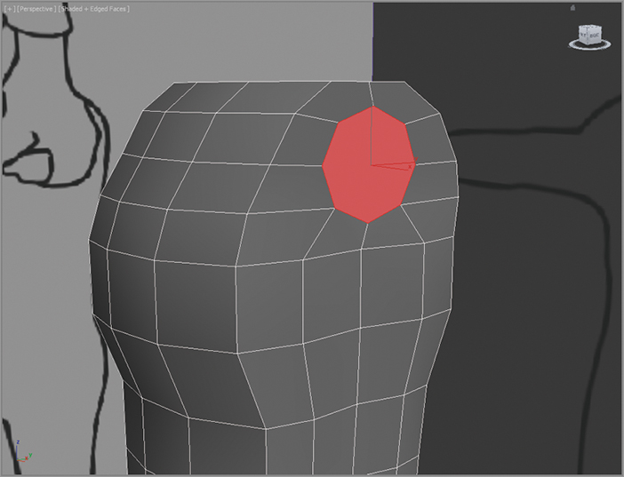
8. Switch to Vertex mode and select the vertex on the left side below the top edge, as shown in
Figure 7-10, left image. Select Poly: Edit ⇒ Edit Polygons, and click the Chamfer Settings shown in an arrow below the Chamfer button. Doing so opens the Tool caddy. Use a Vertex Chamfer Amount value of
4.808, and click the green check-mark button (OK) in the caddy to commit the action, as shown in
Figure 7-10, right image. This is where the arm will be positioned.
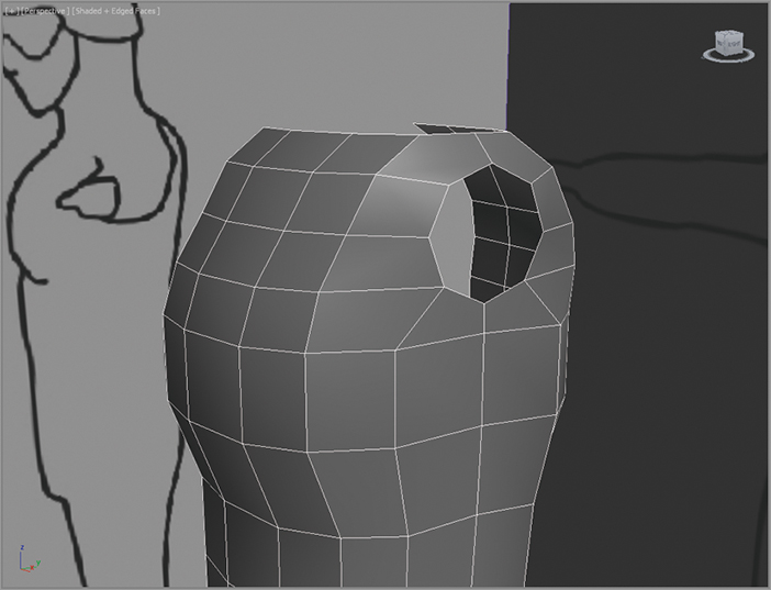
9. Switch to Polygon mode (4), select the new diamond-shaped polygon in the middle, and press Delete to delete the polygon. A hole appears where the arm will be positioned. Also, while in Polygon mode, select all the polygons on the inside edge of the torso model (the side opposite of the new armhole) and delete.
10. Switch to Edge mode (2) and select the four diagonal edges of the diamond-shaped hole and the four edges shown in
Figure 7-11.
11. Select Poly: Edit ⇒ Selction ⇒ Ring Selection, and select the ring of edges running across the top of the chest. Again in the Poly: Edit ⇒ Edges ⇒ Flow Connect to create more horizontal divisions for the upper chest. Flow Connect connects selected edges across one or more edge rings and adjusts the new loop position to fit the shape of the surrounding mesh. The newly created edges are illustrated in
Figure 7-12. The diamond-shaped hole in the shoulder is now more rounded (the hole is now an octagon) as well, since more edges were created at the hole. The dashed lines show the loops running behind the model.
12. Select the two horizontal edges under the armhole, as shown in
Figure 7-13 (left). Select Poly: Edit ⇒ Selction ⇒ Ring Selection, and then select the horizontal edges running down the side, top, and bottom of the torso. Again, select Poly: Edit ⇒ Edges ⇒ Flow Connect to create two new loops of edges, as shown on the right in
Figure 7-13.
13. The new edge ring does not reach all the way up to the octagon armhole. You will need to cut an edge from the top of the new edges you just made, to the bottom of the armhole. Select Poly: Edit ⇒ Favorites Cut

, and click on the first vertex under the armhole, and then click on the second vertex above at the armhole to create the first new edge; right-click to commit the edge. You will still be in the Cut tool, so click on the third vertex and create the second new edge up to the fourth vertex shown in
Figure 7-14; right-click to commit the second edge.
14. The armhole isn’t great right now; it will be easier to start from a circular shape rather than the uneven octagon form you have now. Enter Border mode (

), select the armhole’s border, select Poly: Edit ⇒ Geometry (All), and click the Cap Poly tool to create an NGon (a polygon with more than four sides) cap to fill the hole.
15. Go to Polygon mode and select the new NGon. Select Poly: Edit ⇒ Polygons, and click the GeoPoly tool to create a symmetrical polygon from the previous shape, as shown in
Figure 7-15. GeoPoly untangles a polygon and organizes the vertices to form a perfect geometric shape. This will make it easier for you when you create the arm later.
16. Select the new NGon cap you created in step 14 and press Delete to delete the NGon. Also select and delete the top and bottom polygons on the model, as shown in
Figure 7-16 (left).
17. Select Poly: Edit ⇒ Selection and turn on Ignore Backfacing (

). Then select the left-side polygons, as shown in
Figure 7-16 (right), and delete them as well. Your torso should now have only a front, side, and back.
18. Now, select the edge loops on the right of the model and move them closer toward the left, and closer to the center of the model, as shown in
Figure 7-17. You might want to translate or move them on the Y-axis as well. Your goal is to round out the character for a more organic feel.
19. Notice how the armhole’s circle looks neater in
Figure 7-18, but the edges on the right and top are a bit awkward. Enter Vertex mode and move the edges to give the armhole a more rounded feel.
20. Go into Edge mode and select the edge running vertically on the right side of the model’s back, as shown in
Figure 7-19, and move it toward the armhole. This action will make the back rounder.
Now we are starting to see some shape in the torso. Let’s move on to the arms.
Creating the Arms
Continue with the previous exercise’s scene file, or open the Soldier_V02.max scene file in the Scenes file of the Soldier project on the book’s web page.
1. In Border mode, select the armhole’s border, then hold down the Shift key, and with the Move tool, drag out from the body on the X-axis, extruding polygons as you drag. This method is a form of Border Extrude. This method gives you more control over the extrude process because you can more easily choose the axis along which to extrude. Release the mouse button and view your model in the Front viewport to line up the border to the wrist of the arm in the image plane.
2. From the Poly: Edit ⇒ Favorites ⇒ SwiftLoop, and create three edge loops on the arm, evenly spaced over the newly created arm; then turn off the tool.
3. Switch to Vertex mode and move the newly created vertices on the Y-axis to fit the form on the image plane. It is okay to select a group of vertices and scale on the Y-axis to taper that part of the arm to create the wrist.
4. In Edge mode, select and use Loop Selection (Poly: Edit ⇒ Selection ⇒ Loop Selection) on the horizontal edge running around the body under the arm and move the edges down. Repeat the same process with the loop of edges under the previous loop, as shown in
Figure 7-20. This ensures the underarm area geometry is lined up properly, as shown later in
Figure 7-22.
5. In Edge mode, select and use Loop Selection on the horizontal edge running directly at the underarm and move the loop down, as shown in
Figure 7-21. If Loop Selection doesn’t work, just hold down Ctrl and click (Ctrl+click) on the remaining edges to select.
6. In the Front viewport, in Edge mode, select the middle edge on the arm. Select Poly: Edit ⇒ Selection ⇒ Loop Selection, and then choose Edges ⇒ Chamfer ⇒ Chamfer Settings from that ribbon and enter an Edge Chamfer Amount of 2 and a Connect Edge Segments value of 2.
7. Then chamfer the edges to the right and left, using an Edge Chamfer Amount of
3, with a Connect Edge Segments value of
1, as shown in
Figure 7-22. Keep the middle edge a bit tighter together. Because this is the area where the elbow bends, it is a good idea to include more detail there for deformations at the elbow. Your model should have the vertical edges you see in
Figure 7-22.
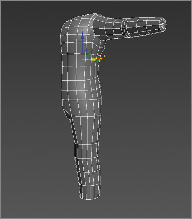
8. In Border mode, select the wrist border and, while holding down the Shift key, use the Scale tool to scale the wrist border down on the Z- and Y-axes into the center, as shown in
Figure 7-23 (left). Using Shift while performing a Scale operation clones the selected objects much as with an extrusion using the Shift+Move method used earlier. In this case, it makes a copy of the border, effectively closing the open end of the wrist.
9. Switch to Vertex mode, select the vertices of the smaller wrist hole, and select Vertices ⇒ Weld ⇒ Weld Settings

to open the Weld Vertices caddy, as shown in
Figure 7-23 (middle). Use a Weld Threshold of
3.39, as shown. This creates a completed cap at the end of the arm, as shown in
Figure 7-23 (right). You will continue with the hand in a later section.
Creating the Legs
Continue with the previous exercise’s scene file, or open the Soldier_V03.max scene file in the Scenes folder of the Soldier project downloaded from the book’s web page.
1. In Edge mode, select the bottommost loop of edges on the model’s torso. Now hold Shift+Move (hold down the Shift key while moving with the Move tool, as you did in the previous set of steps) to create a new extrusion all the way down to the groin in the reference illustration. You will extrude and move down on the Y-axis, as shown in
Figure 7-24.
2. You are starting to prepare the model for the legs and groin area. Use the Cut tool (accessed by selecting Poly: Edit ⇒ Favorites ⇒ Cut), and cut an edge from about 25 percent to the right from the corner of the bottommost edge of the model, to the top corner on the polygon closest to the groin, as shown in
Figure 7-25 (left). Do the same for the polygon at the back of the model in the corresponding corner.
3. In Vertex mode, select the lowest inside vertices and move them up a bit to create a diagonal edge. Do this for both the front and back of the model, as shown in
Figure 7-25 (right).
4. In Edge mode, select both of the new diagonal edges (front and back), then choose Poly: Edit ⇒ Edges ⇒ Bridge ⇒ Bridge Settings. Use four segments to create a bridge, as shown in
Figure 7-26. Doing so creates a bridge between the front and back.
With the bridge in place, the border edge on the bottom of the torso resembles a capital letter
D, as shown in
Figure 7-26. If you extrude the leg down from here, the inner thigh will be flat. For a better starting point to form the leg, you need to cap the hole as you did with the arm previously.
To begin the upper-thigh extrusion, continue with the following steps to cap the D-shape.
5. Enter Border mode, select the D-shaped border edge, and Shift+Move down on the Z-axis to extrude the upper thigh downward to right above the knee pad, as shown in
Figure 7-27 (left). The knee pad’s position can be seen better in the side reference image plane. Don’t worry; you will adjust the shape to fit the thigh later.
6. With the D-shaped border still selected, select Poly: Edit ⇒ Geometry (All) ⇒ Cap Poly to cap the end of the thigh stump. Enter Poly mode and select the new poly, and then select Poly: Edit ⇒ Polygons ⇒ GeoPoly to make the end of the thigh a more even shape; see
Figure 7-27 (middle).
7. Select the thigh’s end polygon and scale on the X-axis, as shown in
Figure 7-27 (right), to create a more oval shape. Then delete the cap so the bottom of the leg is open once again.
8. In the Front viewport, switch to Vertex mode and scale and move the vertices on the leg to match the image plane. Check the Right viewport and shape the thigh as needed. Notice the bottom of the geometry should be located at about the top of the knee pad. Use the Perspective viewport often to make sure some of the vertices are not being accidentally moved.
9. On the inside of the groin area where you created the four-segment bridge in step 4, move the edges to make sure the segments are evenly spaced. This step should be repeated throughout the exercise to keep edges evenly spaced and ensure that the model is organized and clean.
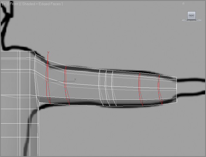
10. Switch to Border mode and select the border opening at the bottom of the leg. Then use the Extrude Border method (hold Shift+Move) to extrude the leg down to the ankle, as shown in
Figure 7-28 (left).
11. Choose Poly: Edit ⇒ Favorites ⇒ SwiftLoop, and create three new horizontal segments around the leg, as shown in
Figure 7-28 (middle). Then fit the vertices to the shape of the soldier’s leg in the side image plane in the Right viewport, as shown in
Figure 7-28 (right). Go into the Front viewport and do the same to shape the leg properly.
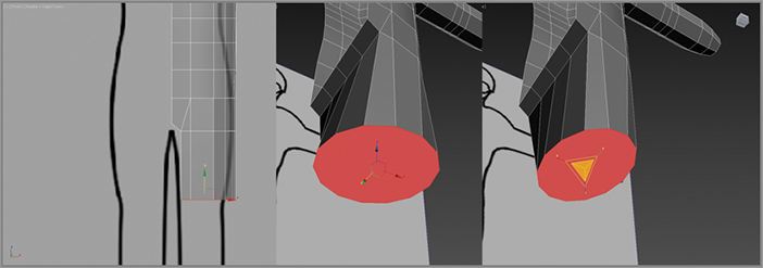
12. In Border mode, select the ankle border, as shown in
Figure 7-29 (left) and Shift+Scale the border down on the Z- and Y-axes and in toward the center of the ankle, leaving a small hole; see
Figure 7-29 (middle). Then switch to Vertex mode and select the vertices around the resulting small hole, and use Weld (Poly: Edit ⇒ Vertices ⇒ Weld) to bring the vertices together, as shown in
Figure 7-29 (right). Adjust the Weld Threshold setting as needed to weld these vertices together.
Fixing Up the Body
Continue with the previous exercise’s scene file, or open the Soldier_V04.max scene file in the Scenes folder of the Soldier project from the book’s web page.
1. The pelvis looks a bit funky. You need to streamline the mesh by combining some edges. Select the vertical edges at the waist (select a single vertical edge from Poly: Edit ⇒ Selection ⇒ Ring Selection); see
Figure 7-30.
2. Right-click to bring up the Quad menu. In the upper-left quad, in the Tools 1 section, choose Collapse. Doing so brings the two horizontal edge loops at the top and bottom of the selected vertical edges together into one edge loop.
3. In the Perspective viewport, use Orbit (use the ViewCube® 3D navigation control or Alt+MMB) to adjust the view to see under the groin area. In Edge or Vertex mode, move the segments to round out that section, as shown in
Figure 7-31.
4. In the Perspective viewport, use Orbit again around the leg and look for any spikes or pinches that may have occurred in the model. The goal is to split the difference between edges so that they’re as close to 50 percent from another edge as possible.
Save your work! Keep in mind that a joint edge, such as the edges that make up the knee or elbow, need to stay where they are. Figure 7-32 shows the leg with good edge spacing. Take a moment to go back through the model and tweak the rest of it until you feel it is right. When you’re modeling for animation, the mesh flow is an important factor.
The Essentials and Beyond
This chapter explored and explained several tools used in modeling, organic and otherwise, to begin the basic form of the soldier character. Reference planes of the soldier design were used at first, and then from a simple box, a torso was formed to match the general shapes shown in the reference images. The arms and legs were extruded and shaped to match as well. As you can see, the more that you model, the easier the process becomes, and the more detailed and finessed your models will turn out.
Additional Exercises
- Try creating a character of your own. A female character or something more edgy like an alien. Get reference images or draw out what you want the character to look like, scan the drawings and use them for reference. Use and expand on the techniques used in this chapter and Chapters 8 and 9.