
Heavy hydrocarbon gasification for synthetic fuel production
J.G. Speight CD&W Inc., Laramie, WY, USA
Abstract
The gasification of residua, petroleum coke, or other heavy feedstocks to generate synthesis gas, produces a clean fuel for firing in a gas turbine. Gasification (1) is a well-established technology, (2) has broad flexibility of feedstocks and operation, and (3) is the most environmentally friendly route for handling these feedstocks for power production. Thus, the gasification of such feedstocks to produce hydrogen and/or power will be an attractive option for the refiner. The premise that the gasification section of a refinery will be the garbage can for deasphalter residues, high-sulfur coke, and other refinery wastes is worthy of consideration.
10.1 Introduction
Heavy feedstocks (hydrocarbonaceous materials, residua, process residues, process bottoms) are nonvolatile materials that are not truly hydrocarbons insofar as they contain elements other than carbon and hydrogen. As with other gasification processes, the gasification of heavy feedstocks involves the complete thermal decomposition of the feedstock into gaseous products (Speight, 2014; Wolff & Vliegenthart, 2011). The term heavy hydrocarbons is often applied to residua, but it is, in fact, an incorrect term because the residua are not composed of true hydrocarbons – the so-called hydrocarbons in residua contain elements other than carbon and hydrogen.
Typically, gasification of heavy feedstocks is carried out at high temperature (> 1000 °C, > 1830 °F), producing synthesis gas (syngas), some carbon black, and ash as major products, and the amount of ash depends on the amount of mineral matter in the feedstock. The integrated gasification combined cycle (IGCC) is an alternative process for residua conversion and is a known and used technology within the refining industry for (1) hydrogen production, (2) fuel gas production, and (3) power generation, which, when coupled with efficient gas-cleaning methods, has a minimal effect on the environment (low SOx and NOx) (Speight, 2013c, 2013d; Wolff, 2007).
The ability of the gasification process to handle heavy crude oil, tar sand bitumen, or any refinery bottom streams enhances the economic potential of most refineries and oil fields (Goldhammer et al., 2008). Upgrading heavy crude oil – either in the oil field at the source or residua in the refinery – is (and will continue to be) an increasingly prevalent means of extracting maximum value from each barrel of oil produced (Speight, 2011a, 2014). Upgrading can convert marginal heavy crude oil into light, higher value crude, and can convert heavy, sour refinery bottoms into valuable transportation fuels. On the other hand, most upgrading techniques leave behind an even heavier residue and the costs deposition of such a by-product may approach the value of the production of liquid fuels and other saleable products. In short, the gasification of residua, petroleum coke, or other heavy feedstocks to generate synthesis gas produces a clean fuel for firing in a gas turbine. Gasification (1) is a well-established technology, (2) has broad flexibility of feedstocks and operation, and (3) is the most environmentally friendly route for handling these feedstocks for power production.
Within the refinery, residuum coking and solvent deasphalting have been used for several decades to upgrade bottoms streams to intermediate products that may be processed to produce transportation fuels (Gary, Handwerk, & Kaiser, 2007; Hsu & Robinson, 2006; Speight, 2011a, 2014; Speight & Ozum, 2002). The installation of a gasifier in a refinery is a realistic option for the conversion of heavy feedstocks leading to the production of added value. In fact, the flexicoking process uses a gasifier as an integral part of the system to convert excess coke to fuel gas (Gary et al., 2007; Gray & Tomlinson, 2000; Hsu & Robinson, 2006; Speight, 2011a, 2014; Speight & Ozum, 2002; Sutikno & Turini, 2012). Thus, by integrating the gasifier as a fully functional process option with gasification, important synergies may be realized and include: (1) increased crude and fuel flexibility, (2) enhanced profitability through reduced capital and operating cost, (3) lower environmental emissions, and (4) increased reliability and efficiency of utilities. Indeed, the integration between bottoms processing units and gasification can serve as a springboard for other economically enhancing integration. The integration of gasification with new or existing hydroprocessing and power generation units presents some unique synergies that will enhance the efficiency of a refinery.
The production of high-quality fuels will result in a higher demand for related hydrogen and conversion technologies. Furthermore, the trend towards low-sulfur fuels and changes in the product mix of refineries will affect technology choice and needs. For example, the current desulfurization and conversion technologies use relatively large amounts of hydrogen, which is an energy intensive product, and increased hydrogen consumption will lead to increased energy use and operation expenses, unless more efficient technologies for hydrogen production are developed.
The demand for high-value petroleum products will maximize production of transportation fuels at the expense of both residua and light gases. Hydroprocessing of residua will be widespread rather than appearing in selected refineries. At the same time, hydrotreated residua will be the common feedstocks for fluid catalytic cracking units. Also, additional conversion capacity will be necessary to process increasingly heavier crudes and meet a reduced demand for residua.
Thus, the gasification of such feedstocks to produce hydrogen, power, or both will be an attractive option for refiners (Campbell, 1997; Dickenson, Biasca, Schulman, & Johnson, 1997; Fleshman, 1997; Gross & Wolff, 2000; Speight, 2011a). The premise that the gasification section of a refinery will be the garbage can for deasphalter residues, high-sulfur coke, and other refinery wastes is worthy of consideration.
10.2 Heavy feedstocks
Heavy feedstocks are materials such as petroleum residua, heavy oils, tar sand bitumen, and petroleum coke that have low volatility. In fact many such materials have no volatility. However, for the purposes of this chapter, non-volatile products from other sources, such as coal and oil shale, are not included. Furthermore, it is preferable to use the term heavy feedstocks (or hydrocarbonaceous materials) because the presence of elements other than carbon and hydrogen in these materials means that they are not true hydrocarbons. Thus, the term hydrocarbonaceous materials includes (1) petroleum residua, (2) heavy oil, (3) extra heavy oil, (4) tar sand bitumen, and (5) other feedstocks such as petroleum coke, all of which can be used as feedstocks for the gasification process (Table 10.1, Figure 10.1) (Gary et al., 2007; Hsu & Robinson, 2006; Speight, 2011a, 2014; Speight & Ozum, 2002).
Table 10.1
Analysis of various refinery feedstocks for gasification
| Units | Vacuum residue | Visbreaker tar | Asphalt | Petcoke | |
| Ultimate analysis | |||||
| C | wt/wt | 84.9% | 86.1% | 85.1% | 88.6% |
| H | wt/wt | 10.4% | 10.4% | 9.1% | 2.8% |
| Na | wt/wt | 0.5% | 0.6% | 0.7% | 1.1% |
| Sa | wt/wt | 4.2% | 2.4% | 5.1% | 7.3% |
| O | wt/wt | 0.5% | 0.0% | ||
| Ash | wt/wt | 0.0% | 0.1% | 0.2% | |
| Total | wt/wt | 100.0% | 100.0% | 100.0% | 100.0% |
| H2C ratio | mol/mol | 0.727 | 0.720 | 0.640 | 0.188 |
| Density | |||||
| Specific gravity | 60°/60° | 1.028 | 1.008 | 1.070 | 0.883 |
| API gravity | °API | 6.2 | 8.88 | 0.8 | - |
| Heating values | |||||
| HHV (dry) | M Btu/lb | 17.72 | 18.6 | 17.28 | 14.85 |
| LHV (dry) | M Btu/lb | 16.77 | 17.6 | 16.45 | 14.48 |

Source: National Energy Technology Laboratory. http://www.netl.doe.gov/technologies/coalpower/gasification/gasifipedia/refinery.html.
a Nitrogen and sulfur contents vary widely.

10.2.1 Petroleum residua
A petroleum resid (residuum, pl. resids, residua) is the non-volatile residue obtained from petroleum after non-destructive distillation has removed all the volatile constituents of the feedstock. The temperature of the distillation unit is usually maintained below 350 °C (660 °F) because the rate of thermal decomposition of petroleum constituents is minimal below this temperature, and the rate of thermal decomposition of petroleum constituents is substantial above 350 °C (660 °F). This is not always the case, however, as residence time in the hot zone is also a factor.
Resids are black, viscous materials and are obtained by distillation of a crude oil under atmospheric pressure (atmospheric residuum) or under reduced pressure (vacuum residuum). They may be liquid at room temperature (generally atmospheric residua) or almost solid (generally vacuum residua) depending upon the nature of the crude oil. When a residuum is obtained from crude oil and thermal decomposition has commenced, many in the industry incorrectly refer to this product as pitch (Speight, 2014). The differences between parent petroleum and the residua are due to the relative amounts of various constituents present, which are removed or remain by virtue of their relative volatility.
The chemical composition of a residuum from is complex. Physical methods of fractionation usually indicate high proportions of asphaltene constituents and resins, even in amounts up to 50% (or higher) of the residuum (Gary et al., 2007; Hsu & Robinson, 2006; Speight, 2011a, 2014; Speight & Ozum, 2002). In addition, the presence of ash-forming metallic constituents, including such organometallic compounds, as those of vanadium and nickel, as well as other metal constituents, is also a distinguishing feature of residua and the non-volatile feedstocks. Furthermore, the deeper the cut into the crude oil, the greater the concentration of sulfur and metals in the residuum and, as a result, the greater the deterioration in physical properties of the residuum (Gary et al., 2007; Hsu & Robinson, 2006; Speight, 2011a, 2014; Speight & Ozum, 2002).
10.2.2 Heavy oil
When crude petroleum can be pumped from a reservoir as a free-flowing dark to light colored liquid, it is often referred to as conventional petroleum. Heavy oil is a type of petroleum that is different from the conventional petroleum insofar as it is more difficult to recover from the reservoir. Heavy oil has a much higher viscosity and lower American Petroleum Institute (API) gravity than conventional petroleum, and primary recovery of heavy oil requires thermal stimulation of the reservoir (Speight, 2008, 2009, 2013a, 2013b, 2014).
The definition of heavy oil is commonly (but incorrectly) based on the API gravity or viscosity. In fact, for many years, petroleum and heavy oil were very generally defined in terms of physical properties, despite a lack of scientific foundation. For example, heavy oils were considered to be those crude oils that had gravity somewhat < 20° API, with the heavy oils falling into the API gravity range 10-15°. For example, Cold Lake heavy crude oil has an API gravity equal to 12°, and extra heavy oils, such as tar sand bitumen, usually have an API gravity in the range 5-10° (Athabasca bitumen = 8° API). Residua would vary depending upon the temperature at which distillation was terminated, but usually, vacuum residua are in the range 2-8° API (Ancheyta & Speight, 2007; Speight, 2000; Speight, 2014; Speight & Ozum, 2002).
10.2.3 Extra heavy oil
Extra heavy oil is also a material that suffers from the use of arbitrary nomenclature. Extra heavy oil occurs in the solid or near-solid state and generally has mobility under reservoir conditions, possibly due to the temperature of the reservoir or deposit rather than the ambient properties of the material. In fact, the term extra heavy oil is a recently evolved term (related to viscosity) of little scientific meaning and often initiates confusion, as it is incorrectly used to refer to tar sand bitumen. While this type of oil may resemble tar sand bitumen and does not flow easily, extra heavy oil is generally recognized as having mobility in the reservoir compared to tar sand bitumen, which is typically incapable of mobility (free flow) under reservoir conditions. For example, the tar sand bitumen located in Alberta, Canada, is not mobile in the deposit and requires extreme methods of recovery to recover the bitumen, while much of the extra heavy oil located in the Orinoco belt of Venezuela requires recovery methods that are less extreme because of the mobility of the material in the reservoir (Speight, 2009, 2013a, 2013b, 2014).
10.2.4 Tar sand bitumen
Also, on occasion, referred to as native asphalt and extra heavy oil, bitumen is a naturally occurring material that is found in tar sand deposits, such as the oil sand deposits in Canada, where the permeability is low and passage of fluids through the deposit can only be achieved by prior application of fracturing techniques. Tar sand bitumen is a high-boiling material with little, if any, material boiling below 350 °C (660 °F), and the properties of this substance may resemble those of an atmospheric residuum. However, to get beyond the use of one or two properties to define tar sand bitumen, tar sands have been defined in the United States (FE-76-4) more correctly and from a functional aspect as:
…the several rock types that contain an extremely viscous hydrocarbon which is not recoverable in its natural state by conventional oil well production methods including currently used enhanced recovery techniques. The hydrocarbon-bearing rocks are variously known as bitumen-rocks oil, impregnated rocks, oil sands, and rock asphalt.
Furthermore, the recovery of the bitumen depends to a large degree on the collective composition of the material, and generally, the bitumen found in tar sand deposits is an extremely viscous material that is immobile under reservoir conditions and cannot be recovered through a well by the application of secondary or enhanced recovery techniques (Speight, 2013a, 2013b, 2014). However, the term tar sand is actually a misnomer; more correctly, the name tar is usually applied to the heavy product remaining after the destructive distillation of coal or other organic matter (Speight, 2013c).
The bitumen in tar sand formations requires a high degree of thermal stimulation for recovery to the extent that some thermal decomposition may have to be induced. Current recovery operations of bitumen in tar sand formations involve the use of a mining technique, and non-mining techniques are continually being developed (Speight, 2009, 2013a, 2013b, 2014).
It is incorrect to refer to native bituminous materials as tar or pitch. Although the word tar is descriptive of the black, heavy bituminous material, those in the industry should avoid its use with respect to natural materials and to restrict the meaning to the volatile or near-volatile products produced in the destructive distillation of organic substances such as coal (Speight, 2013c). Thus, alternative names, such as bituminous sand or oil sand, are gradually finding usage, with the former name being more technically correct. The term oil sand is also used in the same way as the term tar sand, and these terms are used interchangeably throughout this text.
10.2.5 Other feedstocks
Other gasification feedstocks are variable and will depend upon the location of the refinery into which the gasifier has been integrated. Such feedstocks may arise from fossil fuel and from non-fossil fuel sources (Speight, 2008, 2011a, 2011b).
10.2.5.1 Petroleum coke
Another noteworthy feedstock for the gasification processes is petroleum coke, which is the residue left by the destructive distillation of petroleum residua (Gray & Tomlinson, 2000; Patel, 1982; Speight, 2008, 2014). Petroleum coke formed in catalytic cracking operations is usually non-recoverable, as it is often employed as fuel for the process. The composition of petroleum coke also varies with the source of the crude oil, but in general, large amounts of high-molecular-weight complex hydrocarbons, which are rich in carbon but correspondingly poor in hydrogen, make up a high proportion of the coke. The solubility of petroleum coke in carbon disulfide has been reported to be as high as 50-80% w/w, but this is in fact a misnomer, since the coke is the insoluble, honeycomb material that is the end product of thermal processes.
Delayed coking can produce three physical structures of coke: (1) shot coke, (2) sponge coke, or (3) needle coke.
Shot coke is an abnormal type of coke resembling small balls. Due to mechanisms not well understood, the coke from some coker feedstocks forms small, tight, non-attached clusters that look like pellets, marbles, or ball bearings. Shot coke is usually a very hard coke with a low Hardgrove grindability index (Speight, 2013a, 2013b, 2013c, 2013d, 2014). Such coke is less desirable to end users because of difficulties in handling and grinding. It is believed that feedstocks high in asphaltene constituents and with low API favor shot coke formation. Blending aromatic materials with the feedstock, increasing the recycle ratio, or both reduces the yield of shot coke. Fluidization in the coke drums may cause the formation of shot coke. Occasionally, the smaller shot coke may agglomerate into ostrich egg sized pieces. While shot coke may look like it is entirely made up of shot, most shot coke is not 100% shot.
Sponge coke is the common type of coke produced by delayed coking units (Gary et al., 2007; Hsu & Robinson, 2006; Speight, 2011a, 2014; Speight & Ozum, 2002). It is in a form that resembles a sponge and has been called honeycombed. Sponge coke, which is mostly used for anode-grade, is dull and black, with a porous, amorphous structure.
Needle coke (acicular coke) is a special quality coke produced from aromatic feedstocks. Needle coke is silver-gray, with a crystalline broken needle structure, and it is believed to be chemically produced through the crosslinking of condensed aromatic hydrocarbons during coking reactions. It has a crystalline structure with more unidirectional pores and is used in the production of electrodes for the steel and aluminum industries, making it particularly valuable because the electrodes must be replaced regularly.
Petroleum coke is employed for a number of purposes, but its chief use (subject to composition and properties) is in the manufacture of carbon electrodes for aluminum refining. As these electrodes require a high-purity carbon that is low in ash and sulfur free, the volatile matter must be removed by calcining. In addition to its use as a metallurgical reducing agent, petroleum coke is employed in the manufacture of carbon brushes, silicon carbide abrasives, and structural carbon (e.g., pipes and Rashig rings), as well as calcium carbide manufacture from which acetylene is produced:
![]()
![]()
Coke that is unsuitable for any of the above applications is used either as a fuel for the refinery or as a source of synthesis gas and hydrogen. In either case the presence of nitrogen, oxygen, sulfur, and metals in the coke feedstock requires that the gaseous products be subject to thorough gas-cleaning methods (Speight, 2014).
10.2.5.2 Solvent deasphalter bottoms
The deasphalting unit (deasphalter) is a unit in a petroleum refinery for bitumen upgrading that separates an asphalt-like product from petroleum, heavy oil, or bitumen. The deasphalter unit is usually placed after the vacuum distillation tower, where, by the use of a low-boiling liquid hydrocarbon solvent, such as propane or butane under pressure, the insoluble asphalt-like product (deasphalter bottoms) is separated from the feedstock. The other output from the deasphalter is deasphalted oil.
The solvent deasphalting process has been employed for more than six decades to separate high molecular weight fractions of crude oil boiling beyond the range of economical commercial distillation. The earliest commercial applications of solvent deasphalting used liquid propane as the solvent to extract high quality lubricating oil bright stock from vacuum residue. The process has been extended to the preparation of catalytic cracking feeds, hydrocracking feeds, hydrodesulfurization feedstocks, and asphalts. The latter product (asphalt, also called deasphalter bottoms) is used for road asphalt manufacture, refinery fuel, or gasification feedstock for hydrogen production.
In fact, the combination of ROSE solvent deasphalting and gasification has been commercially proven at the ERG Petroli refinery (Bernetti, De Franchis, Moretta, & Shah, 2000). The combination is very synergistic and offers a number of advantages, including a low-cost gasifier feedstock that enhances refinery economics. The process then converts low-value feedstock to high-value products such as power, steam, hydrogen, and chemical feedstock. The process also improves the economics of the refinery by eliminating or reducing the production of low-value fuel oil and maximizing the production of transportation fuel.
10.3 Synthesis gas production
Heavy feedstocks are gasified, and the produced gas is purified into clean fuel gas (Gross & Wolff, 2000), for example:
![]()
As an example, solvent deasphalter residuum is gasified using the partial oxidation (POX) method under a pressure of about 570 psi and at a temperature between 1300 and 1500 °C (2370 and 2730 °F) (Bernetti et al., 2000). The high-temperature-generated gas flows into a waste heat boiler, in which the hot gas is cooled and high-pressure-saturated steam is generated. The gas from the waste heat boiler is then heat-exchanged with the fuel gas and flows to the carbon scrubber, where particulate matter is removed from the generated gas by water scrubbing. The fuel gas and boiler feed water further cool the gas from the carbon scrubber before it enters the sulfur compound removal section, where hydrogen sulfide (H2S) and carbonyl sulfide (COS) are removed from the gas to obtain clean fuel gas. Hydrogen sulfide and carbonyl sulfide are not always present, however, and their presence is dependent upon the operational parameters of the gasification process. If the gas is designated as fuel gas, the clean gas is heated with the hot gas generated in the gasifier and finally supplied to the gas turbine at a temperature of 250-300 °C (480-570 °F).
The exhaust gas from the gas turbine, which has a temperature of about 550-600 °C (1020-1110 °F), flows into the heat recovery steam generator consisting of five heat exchange elements. The first element is a superheater in which the combined stream of the high-pressure-saturated steam generated in the waste heat boiler and in the second element (high-pressure steam evaporator) is super-heated. The third element is an economizer. The fourth element is a low-pressure steam evaporator, and the fifth element is a de-aerator heater. The off-gas from heat recovery steam generator, with a temperature of about 130 °C, is then emitted into the air via a stack.
Two methods can be applied to decrease the nitrogen oxide (NOx) content in the flue gas. The first method is the injection of water into the gas turbine combustor. The second method is to selectively reduce the nitrogen oxide content by injecting ammonia gas in the presence of a de-NOx catalyst that is packed in a proper position of the steam generator. The latter is more effective that the former to lower the nitrogen oxide emissions to the air.
The process for producing synthesis gas typically has three components: (1) synthesis gas generation, (2) waste heat recovery, and (3) gas processing. Within each of these components, there are several options. For example, synthesis gas can be generated to yield a range of compositions ranging from high-purity hydrogen to high-purity carbon monoxide. Three major routes can be utilized for high purity gas production: (1) pressure-swing adsorption, (2) utilization of a cryogenic procedure, where separation is achieved using low temperatures, and (3) permeable membrane technology, which is increasingly common (Speight, 2007, 2014).
10.3.1 POX technology
POX is the most commonly used process for the gasification of heavy oils and other refinery residues, although virtually all mixtures are suitable feedstocks, regardless of volatility (Liebner, 2000). However, aside from special applications, gasification is a bottom-of-the-barrel process that converts feedstocks containing sulfur and nitrogen to a clean synthesis gas consisting mainly of hydrogen and carbon monoxide. In fact, gasification is replacing direct combustion due to environmental regulations, since ash removal and flue gas clean-up are more difficult and expensive than synthesis gas cleaning at elevated pressures.
The main advantages derived from the application of gasification in a refinery are: (1) the capability of processing low-quality, highly viscous, and heavy feedstocks, as well as emulsions (tank sludge), slurries (coke) and other liquid wastes in quench gasifiers; (2) the capability of processing high-sulfur feedstocks because of the almost complete removal of sulfur compounds in the gas treating unit downstream of the gasifier; (3) the possibility of producing hydrogen for the various conversion and upgrading processes of the refinery, with increased production of gas oil, which is a desirable product or feedstock for other refinery units; and (4) the many outlets for synthesis gas, such as hydrogen for the refinery or for export, electricity via the IGCC process, and the production of chemicals such as ammonia, methanol, acetic acid, and oxo-alcohols.
POX or POx reactions occur when a sub-stoichiometric fuel-air mixture is partially combusted in a reformer. The general reaction equation without a catalyst, called thermal partial oxidation (TPOX or TPOx), can be represented as:
![]()
The variable composition of the gasifier feedstocks prevents exact stoichiometric reactions. To produce an equation for such a reaction would only serve to mislead any potential kinetic studies.
A TPOX reactor is similar to the autothermal reactor (ATR), with the main difference being no catalyst is used. The feedstock, which may include steam, is mixed directly with oxygen by an injector that is located near the top of the reaction vessel. Both POX and reforming reactions occur in the combustion zone below the burner.
The principal advantage of the POX process is the ability of the process to accommodate a variety of feedstocks. These feedstocks can include high molecular-weight organic feedstocks, such as petroleum coke (Gunardson & Abrardo, 1999). Additionally, since emissions of nitrogen oxides (NOx) and sulfur oxides (SOx) are minimal, the technology can be considered to be environmentally acceptable. On the other hand, very high temperatures, ~ 1300 °C (2370 °F), are required to achieve a near complete reaction. This high reaction temperature necessitates the consumption of some of the hydrogen and a greater than stoichiometric consumption of oxygen.
10.3.1.1 Shell gasification process
The Shell gasification process (a POX process) is a flexible process for generating synthesis gas, principally hydrogen and carbon monoxide, for the ultimate production of high-purity, high-pressure hydrogen, ammonia, methanol, fuel gas, town gas, or reducing gas. This process uses a reaction of gaseous or liquid hydrocarbons with oxygen, air, or oxygen-enriched air, and the most important step in converting heavy feedstocks into industrial gas is the POX of the oil using oxygen with the addition of steam. The gasification process takes place in a refractory-lined reactor at temperatures of around 1400 °C (2550 °F) and pressures between 30 and 1140 psi. The chemical reactions in the gasification reactor proceed without a catalyst to produce a gas containing carbon at 0.5-2% w/w by weight, depending on the feedstock. The carbon is removed from the gas with water, extracted in most cases with feed oil from the water, and returned to the feed oil. The high reformed gas temperature is utilized in a waste heat boiler for generating steam. The steam is generated at 850-1565 psi, and some of it is used as process steam and for oxygen and oil preheating.
10.3.1.2 Texaco process
The Texaco gasification process (a POX gasification process) generates synthetic gas, principally hydrogen and carbon monoxide. The process is characterized by the injection of feedstock, as well as carbon dioxide, steam or water, into the gasifier. Therefore, this gasification process can use feedstocks such as residua, solvent deasphalted residua, or petroleum coke produced by any coking process. The product gas from the Texaco process can be used for the production of high-purity, high-pressure hydrogen, ammonia, and methanol. The heat recovered from the high temperature gas is also used for the generation of steam in the waste heat boiler. Alternatively, the less expensive quench type configuration is preferred when high-pressure steam is not needed or when a high degree of shift is needed in the downstream carbon monoxide converter.
In the POX process, the gasification reaction is a POX of hydrocarbons to carbon monoxide and hydrogen and can be represented in simple chemical terms:
![]()
![]()
The gasification reaction is instantly completed, thus producing gas mainly consisting of carbon monoxide and hydrogen, and upon leaving the reaction chamber of the gas generator, the high temperature gas enters a quenching chamber usually linked to the bottom of the gas generator, where it is quenched with water to 200-260 °C (390-500 °F).
10.3.1.3 Phillips process
In the Phillips process, petroleum coke is mixed with water to make a pumpable slurry that is then fed into a two-stage gasifier. The slurry reacts readily with the oxygen in the first stage of the gasifier to form hydrogen, carbon monoxide, carbon dioxide, and methane. The high temperature in the first-stage ensures the conversion of all feedstock materials and traps inorganic materials, such as ash and metals, in a glassy matrix resembling coarse sand. This sand-like material (slag) is inert and has an array of uses in the construction industry.
The hot synthesis gas from the horizontal first stage enters the vertical, second stage of the gasifier, where additional slurry is added to increase the energy content of the gas. This two-stage design increases efficiencies, particularly for low reactivity fuels such as petroleum coke. Hot synthesis gas is then cooled in a heat recovery system, producing high-pressure steam in a fire tube boiler.
The dry system improves efficiency over wet systems by removing more particulates, and thus avoiding black-water problems that lead to equipment wear, and it minimizes water consumption and wastewater generation. Sulfur in the synthesis gas is recovered and converted to elemental sulfur, which can be sold in agricultural and other markets. Maximizing sulfur recovery at over 99% of that found in the feedstock, the process recycles all unconverted gases from the tail gas of the sulfur recovery unit to the second stage of the gasifier.
The clean synthesis gas can be further processed, shifting the synthesis gas equilibrium for additional hydrogen production. The required hydrogen purity standards are achieved through a standard pressure-swing adsorption design. The downstream hydrogen production process units also facilitate the capture of carbon dioxide, which can then be compressed and used for enhanced oil recovery or other beneficial uses, or placed in geologic storage. Steam production is achieved through heat recovery steam generators, as needed, for power or steam export to the host facility.
10.3.2 Catalytic partial oxidation
Catalytic partial oxidation (CPOX or CPOx) technology offers possible means of improving the efficiency of synthesis gas production from heavy feedstocks. This technology has several advantages over steam reforming, especially the higher energy efficiency. In fact, the reaction is exothermic rather than endothermic, as is the case with steam reforming. Furthermore, a carbon monoxide-hydrogen ratio (CO/H2) ratio approximately equal to 2.0, which is the ideal ratio for the Fischer-Tropsch process and methanol synthesis, is produced by this technology.
10.3.3 Steam reforming
While not truly the subject of this chapter, steam reforming, which is sometimes referred to as steam-methane reforming (SMR), deserves some consideration because of the production of synthesis gas. The steam reforming process involves passing a preheated mixture essentially composed of methane and steam through catalyst-filled tubes. As the reaction is endothermic, heat must be provided in order to effect the conversion, and the heat is provided by burners located adjacent to the tubes. The product of the process is a mixture of hydrogen, carbon monoxide, and carbon dioxide.
In order to maximize the conversion of the methane feed, both a primary and secondary reformer are generally utilized. A primary reformer is used to effect 90-92% conversion of methane. Here, the hydrocarbon feed partially reacts with steam over a nickel-alumina catalyst to produce a synthesis gas with an H2/CO ratio of ~ 3:1. This partial reaction occurs in a fired tube furnace at 900 °C (1650 °F) and at a pressure of 220-450 psi. The unconverted methane is reacted with oxygen at the top of a secondary autothermal reformer, which contains a nickel catalyst in the lower region of the vessel.
The deposition of carbon can be an acute problem with the use of nickel-based catalysts in the primary reformer (Alstrup, 1988; Rostrup-Neilsen, 1984, 1993). Considerable research has been done with the aim of finding approaches to prevent carbon formation. A successful technique is to use a steam/carbon ratio in the feed gas that does not allow the formation of carbon. However, this method results in lowering the efficiency of the process. Another approach utilizes sulfur passivation, which led to the development of the SPARG process (Rostrup-Neilsen, 1984; Udengaard, Bak-Hansen, Hanson, & Stal, 1992). The SPARG process utilizes the principle that the reaction leading to the deposition of carbon requires a larger number of adjacent surface Ni atoms than does steam reforming. When a fraction of the surface atoms are covered by sulfur, the deposition of carbon is thus more greatly inhibited than it is in steam reforming reactions. A third approach is to use Group VIII metals that do not form carbides, such as platinum (Pt). However, due to the high cost of such metals, using them is not as economical as using nickel.
A major challenge in steam reforming development is its energy intensive nature due to the high endothermic character of the reactions. Thus, the development tends to focus on seeking higher energy efficiency. Improvements in catalysts and metallurgy require adaption to lower steam/carbon ratios and higher heat flux.
10.3.4 Autothermal reforming
In the autothermal reforming process (ATR process), the organic feedstock, steam, and sometimes carbon dioxide are mixed directly with oxygen and air in the reformer. The reformer itself comprises a refractory-lined vessel that contains the catalyst, together with an injector located at the top of the vessel. This type of reformer consists of three zones: (1) the burner in which the feedstock streams are mixed in a turbulent diffusion flame, (2) the combustion zone in which POX reactions produce a mixture of carbon monoxide and hydrogen, and (3) the catalytic zone in which the gases leaving the combustion zone reach thermodynamic equilibrium.
POX reactions occur in a region of the reactor referred to as the combustion zone. The mixture formed in this zone then flows through a catalyst bed where the actual reforming reactions occur. Heat generated in the combustion zone as the result of the POX reactions is utilized in the reforming zone, so that, in the ideal case, the ATR process can exhibit excellent heat balance. In addition, the process offers comparatively flexible operation, including short startup periods and fast load changes, as well as the potential for soot-free operation depending on the feedstock used.
10.3.5 Combined reforming
Combined reforming incorporates the combination of both steam reforming and autothermal reforming. In such a configuration, the feedstock is only partially converted under mild conditions in the first stage to synthesis gas in a relatively small steam reformer. The off-gas from the steam reformer is then sent to an oxygen-fired secondary reactor, the autothermal reforming reactor, where any hydrocarbons in the gas stream are converted to synthesis gas by POX followed by steam reforming. Another configuration requires the feedstock to be split into two streams that are then fed, in parallel, to the steam reforming and autothermal reactors.
10.4 Output products
Synthesis gas processes can produce a range of gases, including carbon monoxide and hydrogen mixtures, high-purity hydrogen, high-purity carbon monoxide, and high-purity carbon dioxide.
If hydrogen is the desired product for refinery operations (Speight, 2014; Sutikno & Turini, 2012; Wolff, 2007), the carbon monoxide-hydrogen ratio can approach infinity by conversion of all of the carbon monoxide to carbon dioxide. By contrast, on the other end, the ratio cannot be adjusted to zero (i.e., 100% v/v hydrogen) because water is always produced with the hydrogen. In fact, a general rule of thumb exists in terms of the hydrogen and carbon monoxide produced by the different gasification processes:
| Gasification process | H2/CO ratio |
| Steam reforming | 3.0-5.0 |
| Steam reforming plus oxygen secondary reforming | 2.5-4.0 |
| Autothermal reforming (ATR) | 1.6-2.65 |
| Partial oxidation (POX) | 1.6-1.9 |
However, in practice, the options are not limited to the ranges shown. Rather, even greater hydrogen-carbon monoxide ratios can be observed if adjustments are made to the process, such as steam adjustment or the inclusion of a shift converter to effect near-equilibrium water-gas-shift conversion.
10.4.1 Gas purification and quality
Purities in excess of 99.5% v/v of either hydrogen or carbon monoxide produced from synthesis gas can be achieved if required by the refinery. Four of the major process technologies available are:
1. Cryogenics plus methanation: This method utilizes a cryogenic process whereby carbon monoxide is liquefied in one or more steps to produce hydrogen with a purity of on the order of 98% v/v. The condensed carbon monoxide, which often contains methane, is distilled to produce a stream of pure carbon monoxide and a mixed stream of carbon monoxide and methane. The mixed carbon monoxide and methane stream can be used as fuel. The hydrogen stream is routed to a shift converter where any remaining carbon monoxide is converted to carbon dioxide and hydrogen. The carbon dioxide is removed, and any further carbon monoxide or carbon dioxide can be removed by methanation. The resulting hydrogen stream can have purity as high as 99.7% v/v.
2. Cryogenics plus pressure-swing adsorption: This method also uses the sequential liquefaction of carbon monoxide to produce hydrogen with a purity of ~ 98% v/v. Again, the carbon monoxide stream can be distilled to remove methane, until it is essentially pure. Depending on the hydrogen purity required, the hydrogen stream is then processed through multiple swings of pressure-swing adsorption cycles until the hydrogen purity is as high as 99.999% v/v.
3. Methane-wash cryogenic process: In this method, liquid carbon monoxide is absorbed into a liquid methane stream so that the resulting hydrogen stream contains ppm levels of carbon monoxide and ~ 5-8% v/v methane. As a result, the purity of the hydrogen stream produced by this process is limited to ~ 95% v/v. The liquid carbon monoxide-/methane stream can be distilled to produce pure carbon monoxide, as well as a carbon monoxide-methane stream that can be used as fuel gas.
4. COsorb process: This method utilizes copper ions (cuprous aluminum chloride, CuAlCl4) in toluene to form a chemical complex with the carbon monoxide, thereby separating it from the product gas steam. This process can capture ~ 96% v/v of the carbon monoxide to produce a carbon monoxide stream having purity > 99% v/v. However, water, hydrogen sulfide, and other trace constituents that can poison the copper catalyst must be removed prior to introduction of the product gas into the reactor. Furthermore, a hydrogen stream of only up to 97% v/v purity is obtained. However, while the efficiency of cryogenic separation decreases with a decrease in the carbon monoxide content of the feedstock gas, the COsorb process is a more efficient process for treating feedstock gas with low carbon monoxide content.
10.4.2 Process optimization
Process optimization includes the development of technologies to facilitate cost-effective gasification of all hydrocarbonaceous feedstocks produced by a refinery, as well as coal and biomass. Thus, the use of high-pressure feed systems and the development of technologies for co-feeding mixtures to high-pressure gasifiers are necessary options. In addition, attention must be given to the use of the refinery gasifier to process waste, reduce the refinery footprint, and produce marketable products.
10.5 Conclusion and future trends
One of the most compelling challenges of the twenty-first century is finding a way to meet national and global energy needs. Petroleum refineries can help meet this challenge, while generating more economic value by adopting a gasification process. There may always be competition for gasification in the processes that convert the heavy feedstocks into added-value products, such as liquid fuels, however.
Accordingly, adding a gasification system to a refinery offers clear benefits (Speight, 2011a), such as (1) the production of power, steam, oxygen, and nitrogen for refinery use or sale (Refineries have typically converted resids and waste or residue into asphalt or bitumen, products from which they may derive very little economic value. Gasification technology, on the other hand, converts this waste into valuable commodities, such as power, steam, oxygen, hydrogen and nitrogen, which are used in everyday refinery operations.); (2) increased efficiency of power generation, improved air emissions, and reduced waste stream versus combustion of petroleum coke or residua or incineration; and (3) the potential to provide high-purity hydrogen used in a variety of refinery operations, such as the removal of impurities though and hydrotreating and hydrocracking processes.
10.5.1 Other uses of residua
The residua (heavy feedstocks, bottoms, hydrocarbonaceous feedstocks) can be routed to other conversion units or blended to heavy industrial fuel, asphalt, or a combination of both. The heavy feedstocks typically have a relatively low economic value, and often they are of lower value than the original crude oil. Thus, most refineries convert or upgrade the low-value heavy feedstocks into more valuable low-boiling products, such as gasoline, jet fuel, and diesel fuel.
Thus upgrading heavy feedstocks creates a need for additional bottom-of-the-barrel processing, both for expansion and for yield improvement. Traditionally, this would automatically call for the addition of atmospheric distillation and/or vacuum distillation units as a starting point. However, there are alternative processing schemes for processing the vacuum or atmospheric residues in order to maximize the value of the heavier crude oils.
10.5.2 Gasification in the future refinery
Hydrogen management has become a priority for current and future refinery operations as consumption continues to rise for greater hydrotreating processes, as well as the processing of heavier and higher sulfur crude oils. In many cases, the hydrogen network is limiting refinery throughput and operating margins. The current main source for hydrogen is the SMR of refinery off-gases and natural gas, an inefficient and cost-incurring process.
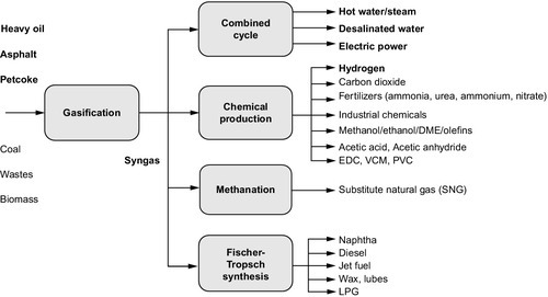
As refineries continue to evolve (Furimsky, 1999; Speight, 2011a), the panacea (rather than the Pandora’s box) for a variety of feedstocks could well be the gasification refinery (Figure 10.1), which is capable of supplying the traditional refined products, while meeting much more severe specifications, and the use of petrochemical intermediates such as olefins, aromatics, hydrogen, and methanol (Figure 10.2) (Breault, 2010; Penrose, Wallace, Kasbaum, Anderson, & Preston, 1999; Phillips & Liu, 2002; Speight, 2011a, 2011b). Furthermore, in addition to the production of synthesis gas, the IGCC) can be used to raise power from feedstocks such as vacuum residua and cracked residua, and a major benefit of IGCC is that power can be produced with the lowest sulfur oxide (SOx) and nitrogen oxide (NOx) emissions of any liquid or solid feed power generation technology.
In fact, the future of the petroleum refining industry will primarily depend on processes for the production of improved quality products. Thus, the refinery of the future will have a gasification section devoted to the conversion of coal and biomass to Fischer-Tropsch hydrocarbons, perhaps even with rich oil shale added to the gasifier feedstock. Many refineries already have gasification capabilities, but over the next two to three decades, the trend will increase to the point where nearly all refineries recognize the need to construct a gasification section to handle residua and a variety of other feedstocks. Biomass, liquids from coal, and liquids from oil shale will increase in importance, and such feedstocks will likely be sent to refineries or processed at a remote location and then blended with refinery stocks. Above all, though, such feedstock must be compatible with refinery feedstocks and not cause fouling, which can lead to process or even refinery shutdown (Speight, 2011a, 2011b).
In the future, computer models for process unit and refinery economics and operations will also be optimized and integrated into plant operations via process computer controls. Alternate fuels for power generation will continue to push crude processing toward higher value products, such as transportation fuels and chemicals. Otherwise, the heavy crude oil and tar sand bitumen that are considered uneconomical to transport to a refinery will be partially refined at their source to facilitate transport, and there will be a new emphasis on partial or full upgrading in situ during recovery operations (Speight, 2009, 2014). In addition, alternative energy sources may become increasingly involved with petroleum, leading to the concept of alternative energy systems (Szklo & Schaeffer, 2005) in which petroleum refining is integrated with the production of energy from other energy sources.
Thus, refinery flexibility will be a key target, especially when related to the increased use of renewable energy sources. And, the industry can begin to work toward such flexibility by incorporating gasification technology into the refinery system as an equal partner in energy production.
In summary, gasification is the only technology allowing refineries to a achieve a zero residue target, as opposed conversion technologies, such as thermal cracking, coking, catalytic cracking, deasphalting, and hydroprocessing, which can only reduce the volume of bottoms, with the complication that the residue qualities generally get worse with the degree of conversion. The flexibility of gasification permits refineries to handle any kind of refinery residue, including petroleum coke and tank bottoms, as well as refinery sludge, while producing a range of value added products, electricity, steam, hydrogen, and various chemicals based on synthesis gas chemistry. The environmental performance of gasification is unmatched because no other technology for processing low-value refinery residues can come close to achieving the emission levels that result from gasification.