
In the old days, floating-point math required using either software emulation or a separate math co-processor. Since the 80486, Intel has incorporated the floating-point operations in an onboard FPU (see Chapter 2, "The IA-32 Platform"). This chapter describes the floating-point operations contained within the FPU and demonstrates how to perform floating-point math on the IA-32 platform.
The first part of this chapter describes the layout of the FPU, and recaps the instructions demonstrated in Chapter 7, "Using Numbers," for loading numbers into the FPU and retrieving results from the FPU. Next, the basic floating-point math functions are shown: addition, subtraction, multiplication, and division. Following that, you will learn how to work with the more advanced floating-point math functions, such as square roots and trigonometric functions. After that, the methods used for comparing floating-point numbers are described, followed by the methods used for storing the FPU environment in memory, and restoring the FPU environment from the backup.
Chapter 2 described the basics of the FPU environment on the IA-32 platform. Now that you are more familiar with the layout and operation of the IA-32 platform, it's time to dig a little deeper and examine both the FPU infrastructure and the instructions that are used to control it. This section describes the FPU register stack: the control word, which controls how the FPU operates; the status word, which indicates what is happening in the FPU; and the tag word, which defines the values contained in the FPU register stack.
As mentioned in Chapter 2, the FPU is a self-contained unit that handles floating-point operations using a set of registers that are set apart from the standard processor registers. The additional FPU registers include eight 80-bit data registers, and three 16-bit registers called the control, status, and tag registers.
The FPU data registers are called R0 through R7 (although as you will see, they are not accessed by these names). They operate somewhat differently than the standard registers in that they are linked together to form a stack. Unlike the stack in memory, the FPU register stack is circular—that is, the last register in the stack links back to the first register in the stack.
The register that is considered the top of the stack is defined in the FPU control word register. It is referenced by the name ST(0). Each of the other registers is referenced relative to the top register, by the name ST(x), where x can be 1 through 7. This is shown in Figure 9-1.
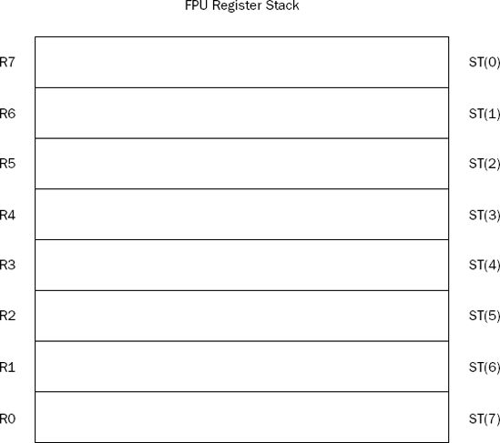
As data is loaded into the FPU stack, the stack top moves downward in the registers. When eight values have been loaded into the stack, all eight FPU data registers have been utilized. If a ninth value is loaded into the stack, the stack pointer wraps around to the first register and replaces the value in that register with the new value, producing an FPU exception error.
Chapter 7 showed how floating-point values can be placed onto the FPU stack using the FLD instruction, integers using the FILD instruction, and BCD data using the FBLD instruction. Various floating-point constant values are also available to load constant values into the stack. There are also commands for storing the values in the FPU register into memory locations in each of the different data types.
Because the FPU is independent of the main processor, it does not normally use the EFLAGS register to indicate results and determine behavior. The FPU contains its own set of registers to perform these functions. The status, control, and tag registers are used to access features and determine the status of the FPU.
This section describes these three FPU registers and shows how to access them in your programs.
The status register indicates the operating condition of the FPU. It is contained in a 16-bit register, with different bits assigned as different flags. The following table describes the status register bits.
Status Bit | Description |
|---|---|
0 | Invalid operation exception flag |
1 | Denormalized operand exception flag |
2 | Zero divide exception flag |
3 | Overflow exception flag |
4 | Underflow exception flag |
5 | Precision exception flag |
6 | Stack fault |
7 | Error summary status |
8 | Condition code bit 0 (C0) |
9 | Condition code bit 1 (C1) |
10 | Condition code bit 2 (C2) |
11-13 | Top of stack pointer |
14 | Condition code bit 3 (C3) |
15 | FPU busy flag |
The four condition code bits (8, 9, 10, and 14) are used together to indicate specific error codes from the result of floating-point operations. They are often used with the exception flags to indicate a specific exception condition. You will see more of these bits in action later in this chapter.
The first six bits are the FPU exception flags. They are set by the FPU when a floating-point exception has occurred during processing. The flags remain set until a program manually clears them. The stack fault flag is set when a stack overflow or underflow condition is detected (values too large or too small for the 80-bit stack registers).
The top of stack bits are used to indicate which FPU data register is set as the ST0 register. Any of the eight registers can be designated as the top of the stack. Each of the subsequent registers is assigned the ST(x) values accordingly.
When values are loaded into the stack, the
TOPvalue is decremented by one before the value is loaded. Thus, because the defaultTOSvalue is zero, theR7register is the default location of the top of stack value (ST0). This can be confusing, but don't worry—the FPU stack takes care of all this for you.
The status register can be read into a doubleword memory location or the AX register, using the FSTSW instruction. This is demonstrated in the getstatus.s program.
# getstatus.s - Get the FPU Status register contents
.section .bss
   .lcomm status, 2
.section .text
.globl _start
_start:
   nop
   fstsw %ax
   fstsw status

   movl $1, %eax
   movl $0, %ebx
   int $0x80
After assembling and linking the program, you can run it in the debugger to see the value that is placed in the AX register and the status memory location:
(gdb) x/x &status
0x804908c <status>:     0x00000000
(gdb) print/x $eax
$1 = 0x0
(gdb)
Both produce the same value, showing that all of the bits in the FPU status register are set to zero by default. You can also view the status, control, and tag FPU registers from the debugger using the info all command:
(gdb) info all
.
.
.
fctrl          0x37f    895
fstat          0x0      0
ftag           0x55555  349525
(gdb)
This shows the current values of the three registers.
The control register controls the floating-point functions within the FPU. Defined here are settings such as the precision the FPU uses to calculate floating-point values, and the method used to round the floating-point results.
The control register uses a 16-bit register, with the bits shown in the following table.
Control Bits | Description |
|---|---|
0 | Invalid operation exception mask |
1 | Denormal operand exception mask |
2 | Zero divide exception mask |
3 | Overflow exception mask |
4 | Underflow exception mask |
5 | Precision exception mask |
6–7 | Reserved |
8–9 | Precision control |
10–11 | Rounding control |
12 | Infinity control |
13–15 | Reserved |
The first six bits of the control register are used to control which exception flags in the status register are used. When one of these bits is set, the corresponding exception flag in the status register is prevented from being set. By default, the mask bits are all set, masking all exceptions.
The precision control bits enable you to set the floating-point precision used for mathematical calculations within the FPU. This is a great control feature, enabling you to change the time the FPU takes to calculate floating-point values. The possible settings of the precision control bits are as follows:
00 — single-precision (24-bit significand)
01 — not used
10 — double-precision (53-bit significand)
11 — double-extended-precision (64-bit significand)
By default, the FPU precision is set to double-extended-precision. This is the most accurate, but also most time-consuming, value. If you are not interested in such high precision, you can set this value to single-precision to speed up your floating-point calculations.
Similarly, the rounding control bits enable you to set how the FPU rounds the results of floating-point calculations. The possible settings of the rounding control bits are as follows:
00 — round to nearest
01 — round down (toward negative infinity)
10 — round up (toward positive infinity)
11 — round toward zero
By default, the rounding control bits are set to round to the nearest value.
The default values of the control register are set to 0x037F. You can use the FSTCW instruction to load the control register settings into a doubleword memory location to see what the settings are. You can also change the settings by using the FLDCW instruction. This instruction loads a doubleword memory value into the control register. The setprec.s program uses the FLDCW instruction to change the FPU precision setting from double-extended to single-precision:
# setprec.s - An example of setting the precision bits in the Control Register
.section .data
newvalue:
   .byte 0x7f, 0x00
.section .bss
   .lcomm control, 2
.section .text
.globl _start
_start:
   nop
   fstcw control
   fldcw newvalue
   fstcw control

   movl $1, %eax
   movl $0, %ebx
   int $0x80
The setprec.s program defines a doubleword value newvalue as 0x07f (remember to use little-endian format when storing the bytes in memory). This value sets the precision bits to 00, which sets the FPU precision to single-precision floating-point. It then uses the FSTCW instruction to retrieve the current control register settings into the control doubleword memory location, and uses the FLDCW instruction to load the newvalue value into the control register. To ensure that the value was stored properly, the FSTCW instruction is used again to check the current control register value.
After assembling and linking the program, you can step through the instructions and watch the value of the control register in the debugger:
(gdb) run
Starting program: /home/rich/palp/chap09/setprec

Breakpoint 1, _start () at setprec.s:11
11         fstcw control
(gdb) x/x &control
0x804909c <control>:    0x00000000
(gdb) s
12         fldcw newvalue
(gdb) x/x &control
0x804909c <control>:    0x0000037f
(gdb) s
13         fstcw control
(gdb) s
15         movl $1, %eax
(gdb) x/x &control
0x804909c <control>:    0x0000007f
(gdb) info all
.
.
fctrl          0x7f     127
(gdb)
The control register was successfully set to 0x07f, so the FPU is now using single-precision floating-point calculations.
This does not necessarily speed up all floating-point calculations. The most common functions that will show improvement are division and square root calculations.
The tag register is used to identify the values within the eight 80-bit FPU data registers. The tag register uses 16 bits (2 bits per register) to identify the contents of each FPU data register. This is shown in Figure 9-2.
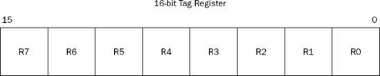
Each tag value corresponds to a physical FPU register. The 2-bit value for each register can contain one of four special codes indicating the content of the register. At any given time, an FPU data register can contain the following:
A valid double-extended-precision value (code 00)
A zero value (code 01)
A special floating-point value (code 10)
Nothing (empty) (code 11)
This enables programmers to perform a quick check of the tag register to determine whether valid data may be in an FPU register, instead of having to read and analyze the contents of the register, although in practice, because you are the one putting the values into the register stack, you should know what is there.
Chapter 7 touched on loading floating-point values into the FPU register stack. In order to perform floating-point math, it is crucial that you understand how data is manipulated on the FPU stack. This is where all of the FPU mathematical operations are performed. You must know how to maneuver data onto and within the stack to process your calculations. The following stacktest.s program demonstrates how to load various data types onto the FPU stack, as well as some common stack functions used when working with the FPU stack:
# stacktest.s - An example of working with the FPU stack
.section .data
value1:
   .int 40
value2:
   .float 92.4405
value3:
   .double 221.440321
.section .bss
   .lcomm int1, 4
   .lcomm control, 2
   .lcomm status, 2
   .lcomm result, 4
.section .text
.globl _start
_start:
   nop
   finit
   fstcw control
   fstsw status
   filds value1
   fists int1
   flds value2
   fldl value3
   fst %st(4)
   fxch %st(1)
   fstps result
   movl $1, %eax
   movl $0, %ebx
   int $0x80
There's a lot going on in this simple program, so let's take this slowly. First, the FINIT instruction is used to initialize the FPU. It sets the control and status registers to their default values, but it does not alter the data contained in the FPU data registers. It is always a good idea to include this instruction in any program that utilizes the FPU.
Following that, the FPU control and status registers are copied to memory locations using the FSTCW and FSTSW instructions. You can view the default values of these resisters by observing these memory locations after the instructions execute:
(gdb) x/2b &control
0x80490cc <control>:    0x7f    0x03
(gdb) x/2b &status
0x80490ce <status>:     0x00    0x00
(gdb)
The output shows that the control register defaulted to the value 0x037f (remember that the value is placed in memory in little-endian format), and the status register defaulted to 0x0000.
The next instruction (FILDS) loads a doubleword integer value into the FPU register stack. The FISTS instruction retrieves the value at the top of the register stack (the value you just placed there) and places it into the destination (which was set to the int1 memory location):
(gdb) info all
.
.
st0            40       (raw 0x4004a000000000000000)
(gdb) x/d &int1
0x80490c8 <int1>:       40
(gdb)
The integer value of 40 was stored in the register tagged as the top of the stack (denoted as ST0). However, notice the hexadecimal value of the stored value. It is pretty easy to see that it is not stored as a normal signed integer value. Instead, the value was converted to the double-extended floating-point data type when it was stored in the FPU register. When the value was retrieved from the FPU register stack and placed in memory, it was automatically converted back to a doubleword integer (because the S character was specified on the FIST mnemonic). You can check that by looking at the hexadecimal value of the memory location:
(gdb) x/4b &int1
0x80490c8 <int1>:       0x28    0x00    0x00    0x00
(gdb)
As expected, the value was stored as a doubleword signed integer value in memory.
The next two instructions load floating-point values into the FPU register stack. The first one uses the FLDS instruction to load a single-precision floating-point value located in the value2 memory location. The second uses the FLDL instruction to load a double-precision floating-point value located in the value3 memory location. Now there are three values loaded into the FPU register stack. As each value is loaded, the preceding values shift down the stack, relative to the top of the stack.
After the FLD instructions, your FPU register stack should look like this:
(gdb) info all
.
.
st0    221.44032100000001150874595623463392  (raw 0x4006dd70b8e086bdf800)
st1    92.44049835205078125  (raw 0x4005b8e1890000000000)
st2    40    (raw 0x4004a000000000000000)
(gdb)
When you display the FPU registers using the info all command, you may notice that the other FPU data registers may or may not contain extraneous data. When the FINIT instruction is executed, it does not initialize the FPU data registers but changes the tag values to show that they are empty. It is possible that extraneous data remains from other operations. It is your job to keep track of what FPU data registers your program uses, and what registers have valid data in them.
Finally, the last three FPU instructions do some data-moving between registers. The FST instruction is used to move data from the ST0 register to another FPU register. Notice the format that is used to specify the fifth FPU register from the top of the stack. The GNU assembler uses the percent sign to indicate a register value, and the FPU register reference number must be enclosed in parentheses.
After the FST instruction, the FXCH instruction is used to exchange the value of the ST0 register with another FPU register—in this case, ST1. After these two instructions, the FPU registers should look like the following:
(gdb) info all
.
.
st0    92.44049835205078125  (raw 0x4005b8e1890000000000)
st1    221.44032100000001150874595623463392  (raw 0x4006dd70b8e086bdf800)
st2    40    (raw 0x4004a000000000000000)
st3    0     (raw 0x00000000000000000000)
st4    221.44032100000001150874595623463392  (raw 0x4006dd70b8e086bdf800)
(gdb)
After you have maneuvered the data around the FPU register stack and performed your required mathematical operations, you will most likely need to retrieve the results from the FPU register stack. The FST and FSTP instructions can also be used to move data from an FPU register to a memory location. The FST instruction copies data from the ST0 FTP register to a memory location (or another FPU register) while keeping the original value in the ST0 register.
The FSTP instruction also copies the ST0 FPU register value, but then pops it from the FPU register stack. This shifts all of the FPU stack values up one place in the stack.
Don't forget to add the data size character to the end of the FST and FSTP mnemonics to specify the proper size of the resulting data value. In this example, the FSTPS instruction is used to create a single-precision floating-point value stored in 4 bytes (32 bits) of memory from the value in the ST0 FPU stack position:
(gdb) x/f &result
0x80490cc <result>:     92.4404984
(gdb) x/4b &result
0x80490cc <result>:     0x89    0xe1    0xb8    0x42
(gdb)
After the FSTPS instruction, you can see that the value was removed from the stack, and the other values were "shifted" up one position:
(gdb) info all
.
.
st0   221.44032100000001150874595623463392     (raw 0x4006dd70b8e086800)
st1   40       (raw 0x4004a000000000000000)
st2   0        (raw 0x00000000000000000000)
st3   221.44032100000001150874595623463392     (raw 0x4006dd70b8e086800)
(gdb)
Now that you are comfortable with manipulating floating-point values within the FPU, it's time to start working on performing mathematical operations on the data.
As would be expected, the FPU provides instructions for performing the basic math functions on floating-point values. These basic functions are described in the following table.
Instruction | Description |
|---|---|
FADD | Floating-point addition |
FDIV | |
FDIVR | Reverse floating-point division |
FMUL | |
FSUB | |
FSUBR | Reverse floating-point subtraction |
Actually, each of these functions has separate instructions and formats that can be used to produce six possible functions, depending on exactly what operation you want to perform. For example, the FADD instruction can be used as follows:
FADD source: Add a 32- or 64-bit value from memory to theST0registerFADD %st(x), %st(0): Addst(x)tost(0)and store the result inst(0)FADD %st(0), %st(x): Addst(0)tost(x)and store the result inst(x)FADDP %st(0), %st(x):Addst(0)tost(x), store the result inst(x), and popst(0)FADDP: Addst(0)tost(1), store the result inst(1), and popst(0)FIADD source:Add a 16- or 32-bit integer value tost(0)and store the result inst(0)
Each of the different formats specifies which FPU register is used in the operation, along with how the register is handled after the operation (whether it is kept or popped off of the stack). It is important that you keep track of the status of the FPU register values. Sometimes this can be difficult with complex mathematical operations that perform multiple operations, which store various values in different registers.
With the GNU assembler, things become even more complicated. The instructions that specify a value from memory must also include a one-character size indicator with the mnemonic (s for 32-bit single-precision floating-point values, and l for double-precision floating-point values). And, as usual, the source and destination operands are reversed from what is shown in the Intel literature.
Following are some examples of using the floating-point math instructions:
fadds data1         # add the 32-bit value at data1 to the ST0 register
fmull data1         # multiply the 64-bit value at data1 with the ST0 register
fidiv data1        # divide ST0 by the 32-bit integer value at data1
fsub %st, %st(1)    # subtract the value in ST0 from ST1, and store in ST1
fsub %st(0), %st(1) # subtract the value in ST0 from ST1, and store in ST1
fsub %st(1), %st(0) #subtract the value in ST1 from ST0, and store in ST0
The FSUBR and FDIVR instructions are used to perform reverse subtractions and divisions—that is, the result is the source value subtracted from (or divided by) the destination value, with the result placed in the destination operand location. This is opposite (reverse) of how the FSUB and FDIV instructions perform the calculations. These instructions are handy when you want to swap the order in the mathematical expression without having to use additional instructions to move data between FPU registers.
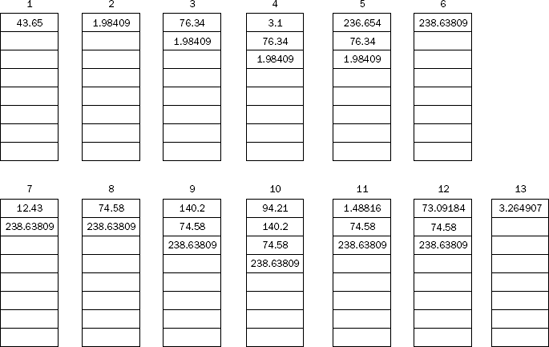
To demonstrate how these instructions work, let's work out a complex mathematical operation using the IA-32 FPU instructions. The mathematical operation to compute is the following:
((43.65 / 22) + (76.34 * 3.1)) / ((12.43 * 6) − (140.2 / 94.21))
To tackle such a problem, it is best to determine how the values will be stored and shifted within the FPU registers. It is always quickest to load as many of the values into the FPU as possible to perform the mathematical operations, without having to swap values back and forth between FPU registers and memory. As new values are loaded, the original values "move down" in the FPU register stack. It is important to keep track of how values are arranged within the stack.
First, you must think about how the values will be loaded into the FPU stack, and how the operations will affect how (and where) the answers are located. Here's a step-by-step analysis of what should happen to perform the calculation:
Load 43.65 into
ST0.Divide
ST0by 22, saving the results inST0.Load 76.34 in
ST0(the answer from step 2 moves toST1).Load 3.1 in
ST0(the value in step 3 moves toST1, and the answer from Step 2 moves toST2).Multiply
ST0andST1, leaving the answer inST0.Add
ST0andST2, leaving the answer inST0(this is the left side of the equation).Load 12.43 into
ST0(the answer from Step 6 moves toST1).Multiply
ST0by 6, leaving the answer inST0.Load 140.2 into
ST0(the answer from Step 8 moves toST1, and from Step 6 toST2).Load 94.21 into
ST0(the answer from Step 8 moves toST2, and from Step 6 toST3).Divide
ST1byST0, popping the stack and saving the results inST0(the answer from Step 8 moves toST1, and from Step 6 toST2).Subtract
ST0fromST1, storing the result inST0(this is the right side of the equation).Divide
ST2byST0, storing the result inST0(this is the final answer).
Often, it is easy to get sidetracked trying to figure out where the individual values are located within the FPU register stack. Sometimes it helps to visualize what is happening. The preceding calculation sequence is illustrated in Figure 9-3.
With the individual steps mapped out on the stack chart, it's pretty easy to see where the values are stored. Now that you have a plan of attack, you can start writing the code to implement it. The fpmath1.s program uses the FPU instructions to carry out this plan:
# fpmath1.s - An example of basic FPU math
.section .data
value1:
   .float 43.65
value2:
   .int 22
value3:
   .float 76.34
value4:
   .float 3.1
value5:
   .float 12.43
value6:
   .int 6
value7:
   .float 140.2
value8:
   .float 94.21
output:
   .asciz "The result is %f
"
.section .text
.globl _start
_start:
nop
   finit
   flds value1
   fidiv value2
   flds value3
   flds value4
   fmul %st(1), %st(0)
   fadd %st(2), %st(0)
   flds value5
   fimul value6
   flds value7
   flds value8
   fdivrp
   fsubr %st(1), %st(0)
   fdivr %st(2), %st(0)
   subl  $8, %esp
   fstpl (%esp)
   pushl $output
   call printf
   add  $12, %esp
   pushl $0
   call exit
The fpmath1.s program defines all of the variables that will be used in the calculation in the data section. It then proceeds through the calculations, loading some values into the FPU registers, and using some values as instruction operands when possible. One specific thing to notice is that the FDIVR and FSUBR instructions came in handy when the destination address (ST0) was the value that was the divisor (or the number to subtract).
After the calculations are complete, the answer is in the ST0 FPU register. The FSTPL instruction is used to pop the value off of the FPU register stack, and in this case it is placed on the top of the program stack using the ESP register value (after reserving 8 bytes on the stack by subtracting eight from ESP). This ensures that the value is available for the printf C function. The printf function requires the floating-point value to be in double-precision format, so the FSTPL instruction must be used.
After assembling the program and linking it with the C libraries, you can run it from the command line to see if you get the correct answer:
$ ./fpmath1
The result is 3.264907
$
The answer produced matches the answer I arrived at (using a calculator, of course). If you are curious to see what is happening under the hood, run the program in the debugger and watch as the FPU registers are manipulated by the instructions.
There is a lot more to floating-point math than simple addition, subtraction, multiplication, and division. Many advanced functions can be performed with floating-point numbers that are provided by the FPU. If you are writing assembly language programs for scientific or engineering applications, you most likely will have to incorporate advanced math functions in your programs.
The following table describes the advanced functions available.
Instruction | Description |
|---|---|
F2XM1 | Computes 2 to the power of the value in ST0, minus 1 |
FABS | Computes the absolute value of the value in ST0 |
FCHS | Changes the sign of the value in ST0 |
FCOS | Computes the cosine of the value in ST0 |
FPATAN | Computes the partial arctangent of the value in ST0 |
FPREM | Computes the partial remainders from dividing the value in ST0 by the value in ST1 |
FPREM1 | Computes the IEEE partial remainders from dividing the value in ST0 by the value in ST1 |
FPTAN | Computes the partial tangent of the value in ST0 |
FRNDINT | Rounds the value in ST0 to the nearest integer |
FSCALE | Computes ST0 to the ST1st power |
FSIN | Computes the sine of the value in ST0 |
FSINCOS | Computes both the sine and cosine of the value in ST0 |
FSQRT | Computes the square root of the value in ST0 |
FYL2X | Computes the value ST1 * log ST0 (base 2 log) |
FYL2XP1 | Computes the value ST1 * log (ST0 + 1) (base 2 log) |
Most of the preceding functions are self-explanatory. The following sections describe some of these functions in more detail.
The FABS, FCHS, FRNDINT, and FSQRT instructions perform simple mathematical functions on the floating-point values. The FABS instruction computes the absolute value of ST(0). The FCHS instruction changes the sign bit of the value. The FSQRT computes the square root of ST(0).
The fpmath2.s demonstrates using these functions:
# fpmath2.s - An example of the FABS, FCHS, and FSQRT instructions
.section .data
value1:
   .float 395.21
value2:
   .float −9145.290
value3:
   .float 64.0
.section .text
.globl _start
_start:
   nop
   finit
   flds value1
   fchs
   flds value2
   fabs
   flds value3
   fsqrt

   movl $1, %eax
   movl $0, %ebx
   int $0x80
After assembling and linking the program, you can watch the FPU registers in the debugger. At the end of the instructions, the FPU registers should look like this:
(gdb) info all
.
.
.
st0       8        (raw 0x40028000000000000000)
st1       9145.2900390625  (raw 0x400c8ee5290000000000)
st2       −395.209991455078125     (raw 0xc007c59ae10000000000)
(gdb)
Remember that the values are in reverse order as they are pushed onto the FPU stack. The ST0 register holds the result from the FSQRT instruction, and the ST2 register holds the result from the FCHS instruction.
The FRNDINT instruction is different in that its behavior is dependent on the value of the rounding bits in the FPU control register. The FRNDINT instruction rounds the floating-point value in ST0 to the nearest integer value, according to one of the four rounding methods described earlier in the "The control register" section. This is demonstrated in the roundtest.s program:
# roundtest.s - An example of the FRNDINT instruction
.section .data
value1:
   .float 3.65
rdown:
   .byte 0x7f, 0x07
rup:
   .byte 0x7f, 0x0b
.section .bss
   .lcomm result1, 4
   .lcomm result2, 4
   .lcomm result3, 4
.section .text
.globl _start
_start:
   nop
   finit
   flds value1
   frndint
   fists result1

   fldcw rdown
   flds value1
   frndint
   fists result2

   fldcw rup
   flds value1
   frndint
   fists result3

   movl $1, %eax
   movl $0, %ebx
   int $0x80
The roundtest.s program defines two doubleword values (rdown and rup) that are used to change the rounding bits in the FPU control register. Because no other values need to be changed, we can do this with a static value. To set rounding to round down, the rounding bits are set to the binary value 01, which makes the control register have the value 0x77F. To set the rounding to round up, the rounding bits are set to the binary value 10, which makes the control register have the value 0xB7F.
The first group of instructions initializes the FPU, loads the test value into ST0, performs the FRNDINT instruction (using the default rounding setting), and moves the result to the result1 memory location (as an integer value):
finit
flds value1
frndint
fists result1
The next group of instructions loads the control register with the value to set rounding to round down, load the ST0 register with the test value, perform the rounding, and then store the result in the result2 memory location:
fldcw rdown
flds value1
frndint
fists result2
The last group of instructions loads the control register with the value to set rounding to round up, load the ST0 register with the test value, perform the rounding, and then store the result in the result3 memory location.
After assembling and linking the program, you can watch how it works by running it in the debugger. After the first group of instructions, the rounded value should be in the result1 memory location:
(gdb) x/d &result1
0x80490c4 <result1>:    4
(gdb)
By default, the floating-point value was rounded up to the integer value 4. After the next group of instructions, the rounded value should be in the result2 memory location:
(gdb) x/d &result2
0x80490c8 <result2>:    3
(gdb)
As expected, by setting the rounding bits to round down, the new rounded value was set to the integer value 3. Finally, after the last group of instructions, the rounded value should be in the result3 memory location:
(gdb) x/d &result3
0x80490cc <result3>:    4
(gdb)
The result shows that the rounding bits are now rounding the values up to the nearest integer.
Partial remainders are a tricky part of floating-point division. The concept of a partial remainder relates to how floating-point division is performed. The remainder of the division operation is determined through a series of subtractions of the divisor from the dividend. Through each subtraction iteration, the intermediate remainder is called the partial remainder. The iterations stop when the partial remainder is less than the divisor (no more subtractions can be performed without creating a negative number). At the end of the division, the final answer is an integer value representing the number of subtraction iterations (called the quotient), and a floating-point value representing the final partial remainder (now called the remainder).
Depending on how many iterations are required to perform the division, there can be many partial remainders. The number of iterations required depends on the difference between the exponent values of the dividend and the divisor. Each subtraction cannot reduce the exponent value of the dividend by more than 63.
The FPREM and FPREM1 instructions both compute the remainder value of a floating-point division, but do it using slightly different methods.
The basic method for determining a division remainder is to determine the floating-point quotient of the division of the dividend and divisor, and then round that value to the nearest integer. The remainder is then the difference of the quotient multiplied by the divisor, and the dividend. For example, to find the remainder for 20.65 divided by 3.97, you would perform the following steps:
20.65 / 3.97 = 5.201511335, rounded = 5 (this is the quotient)
5 * 3.97 = 19.85
20.65 − 19.85 = 0.8 (this is the remainder)
The tricky part is the rounding procedure. Intel developed the FPREM instruction before any standards in partial remainders were created. The Intel developers chose to use the default FPU round toward zero method to find the integer quotient value, and then determine the remainder.
Unfortunately, when the IEEE produced a standard, it chose to round the quotient value up to the nearest integer value before finding the remainder. While this seems to be a subtle difference, it has huge implications when calculating partial remainders along the process. Because of this, Intel chose to keep the original FPREM instruction in its original form, and create the FPREM1 instruction, which uses the IEEE method of calculating the partial remainders.
The problem with calculating partial remainders is that you must know when the iteration process is complete. Both the FPREM and FPREM1 instructions use the FPU status register condition code bit 2 (bit 10 of the status register) to indicate when the iterations are complete. When more iterations are required, the C2 bit is set. When the iterations are complete, the C2 bit is cleared.
To check the C2 bit, you must first use the FSTSW instruction to copy the contents of the status register into either a memory location or the AX register, and then use the TEST instruction to determine whether the bit has been set.
The premtest.s program performs a simple floating-point division using the FPREM1 instruction:
# premtest.s - An example of using the FPREM1 instruction
.section .data
value1:
   .float 20.65
value2:
   .float 3.97
.section .bss
   .lcomm result, 4
.section .text
.globl _start
_start:
   nop
   finit
   flds value2
   flds value1
loop:
   fprem1
   fstsw %ax
   testb $4, %ah
   jnz loop

   fsts result
movl $1, %eax
   movl $0, %ebx
   int $0x80
Because the FPREM1 instruction is an iterative process, there is no guarantee that it will have the final answer on the first pass. The TEST instruction is used to check the value of the C2 condition bit (moved to the AX register with the FSTSW instruction). If the bit is set, the TEST instruction will produce a nonzero value, and the JNZ instruction will jump back to the loop point. When the bit is clear, the TEST instruction produces a zero value, and the JNZ instruction falls through. The remainder value is stored in the ST0 register, which is copied using the FSTS instruction to the result memory location.
After assembling and linking the program, you can run it in the debugger and watch how the FPREM1 instruction determines the remainder value. For the example values shown, the remainder value should look like this:
(gdb) x/f &result
0x80490a8 <result>: 0.799999475
(gdb)
While the remainder value is stored in the ST0 register, the actual quotient value is not stored in a register. The three least significant bits of the quotient value are stored in the control register using the leftover condition code bits as follows:
Quotient bit 0 in condition bit 1
Quotient bit 1 in condition bit 3
Quotient bit 2 in condition bit 0
You must manually extract these bits to form the lower three bits of the quotient value.
While the
FPREMinstruction output may seem odd, there was a reason for it. In the old 80287 FPU co-processor days, theFPTANinstruction could not handle angle radians larger than pi/4. TheFPREMinstruction was crucial in determining the quadrant in which a source angle value was located. Because this involved quadrants, only the lower three bits of the quotient were required. Since the 80387 FPU co-processor, theFPTANinstruction does not have this limitation, and the quotient value from theFPREMinstruction is hardly ever used.
Another huge advantage to the FPU is its ability to calculate trigonometric functions. Normal trig functions such as sine, cosine, and tangent are simple to obtain from the FPU. The following sections demonstrate using the FPU trig functions in assembly language programs.
The basic trig functions are all implemented the same way in the FPU. The instructions use an implied source operand, which is located in the ST0 register. When the function completes, the result is placed in the ST0 register.
The only trick to these functions is that they all use radians for the source operand units. If you are working with an application that uses degrees, the values must be converted to radians before you can use the FPU trig functions. The formula for doing this is as follows:
radians = (degrees * pi) / 180
This calculation can easily be done in the FPU using the following code snippet:
fsts degree1         # load the degrees value stored in memory into ST0
fidivs val180        # divide by the 180 value stored in memory
fldpi                # load pi into ST0, degree/180 now in ST1
fmul %st(1), %st(0)  # multiply degree/180 and pi, saving in ST0
fsin                 # perform trig function on value in ST0
The trigtest1.s program demonstrates these functions:
# trigtest1.s - An example of using the FSIN and FCOS instructions
.section .data
degree1:
   .float 90.0
val180:
   .int 180
.section .bss
   .lcomm radian1, 4
   .lcomm result1, 4
   .lcomm result2, 4
.section .text
.globl _start
_start:
   nop
   finit
   flds degree1
   fidivs val180
   fldpi
   fmul %st(1), %st(0)
   fsts radian1
   fsin
   fsts result1
   flds radian1
   flds radian1
   fcos
   fsts result2

   movl $1, %eax
   movl $0, %ebx
   int $0x80
After the angle is converted from degrees to radians, it is stored in the radian1 memory location. The FSIN instruction is then used to calculate the sine value of the angle, and the FCOS instruction is used to calculate the cosine value. After the program runs, you can view the results in the result1 and result2 memory locations:
(gdb) x/f &result1
0x80490bc <result1>:    1
(gdb) x/f &result2
0x80490c0 <result2>:    −4.37113883e-08
(gdb)
Of course, the sine for a 90-degree angle is one, and the cosine is zero. You can test this with other degree values as well.
In a production program, it would obviously be much faster to precompute the value of pi/180, and store that value in the FPU, rather than have the processor do that all the time.
If you need to obtain both the sine and cosine values of an angle, the FSINCOS instruction enables you to do that in one easy step. The instruction places the sine result in the ST0 register, and then pushes the cosine result onto the FPU register. This normally results in the cosine value being in ST0, and the sine value being in ST1. The trigtest2.s program demonstrates using this instruction:
# trigtest2.s - An example of using the FSINCOS instruction
.section .data
degree1:
   .float 90.0
val180:
   .int 180
.section .bss
   .lcomm sinresult, 4
   .lcomm cosresult, 4
.section .text
.globl _start
_start:
   nop
   finit
   flds degree1
   fidivs val180
   fldpi
   fmul %st(1), %st(0)
   fsincos
   fstps cosresult
   fsts sinresult

   movl $1, %eax
   movl $0, %ebx
   int $0x80
The results of the trigtest2.s program can be seen in the cosresult and sinresult memory locations:
(gdb) x/f &cosresult
0x80490b0 <cosresult>:  −2.71050543e-20
(gdb) x/f &sinresult
0x80490ac <sinresult>:  1
(gdb)
The value of cosresult is not exactly 0 as it should be, but pretty close. The value of sinresult is the correct value of 1.
The FPTAN and FPATAN instructions are somewhat different from their sine and cosine counterparts. While they compute the tangent and arctangent trig functions, the input and output requirements are slightly different.
The FPTAN instruction uses the standard implied operand located in the ST0 register (again, the angle must be in radians, not degrees). The tangent value is calculated and placed in the ST0 register as expected. After that, a value of 1.0 is pushed onto the FPU stack, shifting the tangent result value down to the ST1 register.
The reason for this is to achieve backward compatibility with applications written for the 80287 FPU co-processor. The FSIN and FCOS instructions were not available then, and calculating these required using the reciprocal of the tangent value. By issuing a simple FDIVR instruction after the FPTAN instruction, the cotangent value can be calculated.
The FPATAN instruction uses two implied source operands. It calculates the arctangent of the angle value ST1/ST0 and places the result in ST1, and then pops the FPU stack, moving the value to ST0. This form is available to support finding the arctangent of an infinite ratio—that is, when ST0 is zero. The standard ANSI C function atan2( double x, double y) uses the same idea.
The FPU logarithmic functions provide instructions for performing log base 2 calculations. The FYL2X instruction performs the following calculation:
ST(1) * log2 (ST(0))
The FYL2X1 instruction performs this calculation:
ST(1) * log2 (ST(0) + 1.0)
The FSCALE instruction scales a value in ST(0) by 2 to the power of the value in ST(1). This can be used for both scaling up (by using a positive value in ST(1)) and for scaling down (by using a negative value in ST(1)). The fscaletest.s program demonstrates this principle:
# fscaletest.s - An example of the FSCALE instruction
.section .data
value:
   .float 10.0
scale1:
   .float 2.0
scale2:
   .float −2.0
.section .bss
   .lcomm result1, 4
   .lcomm result2, 4
.section .text
.globl _start
_start:
   nop
   finit
   flds scale1
   flds value
   fscale
   fsts result1

   flds scale2
   flds value
   fscale
   fsts result2

   movl $1, %eax
   movl $0, %ebx
   int $0x80
The first scale value (set to 2.0) is loaded into the ST(0) register, and then the test value (10.0) is loaded (moving the scale value to ST(1) where it belongs). After the FSCALE instruction, the test value is multiplied by 2 to the power of the scale value, which results in multiplying the test value by 4.
Next, the second scale value (set to −2.0) is loaded, along with the test value, and the FSCALE instruction is executed again. This time the negative scale factor divides the test value by 4.
After assembling and linking the program, you can step through the instructions and display the results in the result1 and result2 memory locations:
(gdb) x/f &result1
0x80490b8 <result1>:    40
(gdb) x/f &result2
0x80490bc <result2>:    2.5
(gdb)
The values produced were as expected.
Note that the
FSCALEinstruction provided a handy way to multiply and divide the floating-point values by powers of 2, similar to the effect of the shift instructions used for integers in Chapter 8, "Basic Math Functions."
Although the FPU log functions only provide base 2 logarithms, it is possible to perform calculations using other logarithmic bases. To find a logarithm of another base using base 2 logarithms, you can use the following equation:
log (base b) X = (1/log(base 2) b) * log(base 2) X
This can be easily implemented using the FYL2X instruction. The logtest.s program calculates the base 10 log of a value in memory:
# logtest.s - An example of using the FYL2X instruction
.section .data
value:
   .float 12.0
base:
   .float 10.0
.section .bss
   .lcomm result, 4
.section .text
.globl _start
_start:
   nop
   finit
   fld1
   flds base
   fyl2x
   fld1
   fdivp
   flds value
   fyl2x
   fsts result

   movl $1, %eax
   movl $0, %ebx
   int $0x80
The logtest.s program implements the equation to perform a log base 10 calculation of the value 12.0. It starts off by loading the value 1.0 in the FPU register (the Y value for the first log function), then the value of the base (10.0), performing the base 2 log of the value. This produces the value for the first half of the equation (note that in this example, because the base was chosen as 10, the FLDL2T instruction could be used to load the value into ST(0) with one instruction). This value becomes the new Y value for the next FYL2X instruction, with the X value being the original value (12.0). The final result should be equal to the base 10 log of 12, or 1.07918119.
After assembling and linking the program, the result can be seen by running the program in the debugger and looking at the result memory location:
(gdb) x/f &result
0x80490a8 <result>: 1.07918119
(gdb)
Yes, the logtest.s program produced the correct result for the base 10 log of 12.
Unfortunately, comparing floating-point numbers is not as easy as with integers. When working with integers, it's easy to use the CMP instruction and evaluate the values in the EFLAGS register to determine whether the values were less than, equal to, or greater than.
With floating-point numbers, you do not have the luxury of using the CMP instruction. Instead, the FPU provides some instructions of its own to use when comparing floating-point values
The FCOM family of instructions is used to compare two floating-point values in the FPU. The instructions compare the value loaded in the ST0 FPU register with either another FPU register or a floating-point value in memory. There are also options for popping one or both values off of the FPU stack after the compare. The following table describes the different versions that can be used.
Instruction | Description |
|---|---|
FCOM | Compare the ST0 register with the ST1 register. |
FCOM ST(x) | Compare the ST0 register with another FPU register. |
FCOM source | Compare the ST0 register with a 32- or 64-bit memory value. |
FCOMP | Compare the ST0 register with the ST1 register value and pop the stack. |
FCOMP ST(x) | Compare the ST0 register with another FPU register value and pop the stack. |
FCOMP source | Compare the ST0 register with a 32 or 64-bit memory value and pop the stack. |
FCOMPP | Compare the ST0 register with the ST1 register and pop the stack twice. |
FTST | Compare the ST0 register with the value 0.0. |
The result of the comparison is set in the C0, C2, and C3 condition code bits of the status register. The possible results from the comparison are shown in the following table.
Condition | C3 | C2 | C0 |
|---|---|---|---|
ST0 > source | 0 | 0 | 0 |
ST0 < source | 0 | 0 | 1 |
ST0 = source | 1 | 0 | 0 |
You must use the FSTSW instruction to copy the status register value to the AX register or a memory location, and then use the TEST instruction to determine the result of the comparison.
The fcomtest.s program demonstrates this principle:
# fcomtest.s - An example of the FCOM instruction
.section .data
value1:
   .float 10.923
value2:
   .float 4.5532
.section .text
.globl _start
_start:
   nop
   flds value1
   fcoms value2
   fstsw
   sahf
   ja greater
   jb lessthan
   movl $1, %eax
   movl $0, %ebx
   int $0x80
greater:
   movl $1, %eax
   movl $2, %ebx
   int $0x80
lessthan:
   movl $1, %eax
   movl $1, %ebx
   int $0x80
The fcomtest.s program uses some trickery to determine the result of the FCOM instruction After retrieving the status register from the FPU and saving it in the AX register using the FSTSW instruction, the SAHF instruction is used to load the EFLAGS register from the AH register values.
The SAHF instruction moves bits 0, 2, 4, 6, and 7 of the AH register to the carry, parity, aligned, zero, and sign flags, respectively. The other bits in the EFLAGS register are unaffected. It just so happens (thanks to the Intel software engineers) that these bits in the AH register contain the FPU status register condition code values. Combining the FSTSW and SAHF instructions moves the following:
The C0 bit to the
EFLAGScarry flagThe C2 bit to the
EFLAGSparity flagThe C3 bit to the
EFLAGSzero flag
Once this is done, the EFLAGS carry, parity, and zero flags line up with the C0, C2, and C3 condition code bits, which produces a nice translation for using the JA, JB, and JZ instructions to determine the comparison of the two floating-point values.
The fcomtest.s program produces different result code depending on the values set in memory. The result code can be seen using the echo command:
$ ./fcomtest
$ echo $?
2
$
The result code of 2 indicates that the first value (stored in the value1 memory location) was greater than the second value (stored in the value2 memory location). You can change the values within the program to ensure that the comparisons work properly.
One word about the equal comparison: Remember that when a floating-point value is loaded into a FPU register, it is converted to a double-extended-precision floating-point value. This process may lead to some rounding errors. It is possible that a single- or double-precision value, after being loaded into the FPU register, will not be equal to the original value. It is not a good idea to test floating-point values for equality, but rather to test them to within a small tolerance of the expected value.
You may be wondering why, if using the FSTSW and SAHF instruction combination after the comparison instruction works so well, it is not incorporated into a single instruction. The answer is that it was. Starting in the Pentium Pro processor line, the FCOMI instruction is available to do just that. The FCOMI family of instructions performs the floating-point comparisons and places the results in the EFLAGS registers using the carry, parity, and zero flags.
The following table describes the instructions in the FCOMI family.
Instruction | Description |
|---|---|
FCOMI | Compare the ST0 register with the ST(x) register. |
FCOMIP | Compare the ST0 register with the ST(x) register and pop the stack. |
FUCOMI | Check for unordered values before the comparison. |
FUCOMIP | Check for unordered values before the comparison and pop the stack afterward. |
As you can tell from the table descriptions, one limitation to the FCOMI instruction family is that they can only compare two values in the FPU registers, not a FPU register with a value in memory.
The last two instructions in the table perform a service that is not available with the FCOM instruction family. The FUCOMI and FUCOMIP instructions ensure that the values being compared are valid floating-point numbers (using the FPU tag register). If an unordered value is present, an exception is thrown.
The output of the FCOMI instructions uses the EFLAGS registers, as shown in the following table.
Condition | ZF | PF | CF |
|---|---|---|---|
ST0 > ST(x) | 0 | 0 | 0 |
ST0 < ST(x) | 0 | 0 | 1 |
ST0 = ST(x) | 1 | 0 | 0 |
To prove that the FCOMI instruction works as advertised, the following fcomitest.s program duplicates the scenario of the fcomtest.s program, but using the FCOMI instruction:
# fcomitest.s - An example of the FCOMI instruction
.section .data
value1:
   .float 10.923
value2:
   .float 4.5532
.section .text
.globl _start
_start:
   nop
   flds value2
   flds value1
   fcomi %st(1), %st(0)
   ja greater
   jb lessthan
   movl $1, %eax
   movl $0, %ebx
   int $0x80
greater:
   movl $1, %eax
   movl $2, %ebx
   int $0x80
lessthan:
   movl $1, %eax
   movl $1, %ebx
   int $0x80
Because the FCOMI instruction requires both values to be in the FPU register, they are loaded in opposite order so the value1 value will be in the ST0 register when the comparison is made. After assembling and linking the program, you can run it and view the result code:
$ ./fcomitest
$ echo $?
2
$
The FCOMI instruction produced the same result as the FCOM instruction test program. Again, you can play around with the values to make sure the code does indeed produce the proper result code for different comparisons.
Similar to the CMOV instructions for integers, the FCMOV instructions enable you to program conditional moves of floating-point values. Each of the instructions in the FCMOV family moves the source operand in the ST(x) FPU register with the destination operand in the ST(0) FPU register based on the value of the EFLAGS register. If the condition is true, the value in the ST(x) register is moved to the ST(0) register.
Because the move is based on the EFLAGS register, it is more common for the FCMOV instruction to be preceded by an FCOMI instruction.
The following table outlines the available instructions in the FCMOV family.
Instruction | Description |
|---|---|
FCMOVB | Move if ST(0) is below ST(x). |
FCMOVE | Move if ST(0) is equal to ST(x). |
FCMOVBE | Move if ST(0) is below or equal to ST(x). |
FCMOVU | Move if ST(0) is unordered. |
FCMOVNB | Move if ST(0) is not below ST(x). |
FCMOVNE | Move it ST(0) is not equal to ST(x). |
FCMOVNBE | Move if ST(0) is not below or equal to ST(x). |
FCMOVNU | Move if ST(0) is not unordered. |
The GNU format of the instructions is
fcmovxx source, destination
where source is the ST(x) register, and destination is the ST(0) register.
The fcmovtest.s program demonstrates some simple moves:
# fcmovtest.s - An example of the FCMOVxx instructions
.section .data
value1:
   .float 20.5
value2:
   .float 10.90
.section .text
.globl _start
_start:
   nop
   finit
   flds value1
   flds value2
   fcomi %st(1), %st(0)
   fcmovb %st(1), %st(0)

   movl $1, %eax
   movl $0, %ebx
   int $0x80
The values are loaded into the FPU registers (ST0 = 10.90, and ST1 = 20.5). The FCOMI instruction sets the EFLAGS registers depending on the values in ST0 and ST1. The FCMOVB instruction moves the value in ST1 to ST0 if the value of ST0 is below that of ST1 (which in this case it is).
When the program is assembled and linked, you can check the FPU registers while the program is running to see what happens. After the FCMOVB instruction, both the ST0 and ST1 registers should contain the 20.5 value.
The
FCMOVinstructions are available in the Pentium Pro and later processors. These instructions will not work on earlier IA-32 processors.
Unfortunately, with modern IA-32 processors, the FPU data registers must do double duty. The MMX technology utilizes the FPU data registers as MMX data registers, storing 80-bit packed integer values for calculations. If you use both FPU and MMX functions in the same program, it is possible that you will "step on" your data registers.
To help prevent this, the IA-32 platform has included several instructions that enable you to save the FPU processor state and return to that state after other processing has completed. This section describes the different instructions that can be used to store and retrieve the FPU processor state.
The FSTENV instruction is used for storing the FPU environment in a block of memory. The following FPU registers are stored:
Control register
Status register
Tag register
FPU instruction pointer offset
FPU data pointer
FPU last opcode executed
The values are stored in a 28-byte block of memory. The FLDENV instruction is used to load the memory block values back into the FPU environment. The fpuenv.s program demonstrates these instructions:
# fpuenv.s - An example of the FSTENV and FLDENV instructions
.section .data
value1:
   .float 12.34
value2:
   .float 56.789
rup:
   .byte 0x7f, 0x0b
.section .bss
   .lcomm buffer, 28
.section .text
.globl _start
_start:
   nop
   finit
   flds value1
   flds value2
   fldcw rup
   fstenv buffer

   finit
   flds value2
   flds value1

   fldenv buffer

   movl $1, %eax
   movl $0, %ebx
   int $0x80
The fpuenv.s program initializes the FPU, loads a couple of values into the FPU data registers, modifies the control register to alter the rounding bits, and then stores the result in the buffer memory location. If you look at the buffer location after the FSTENV instruction, it should look like this:
(gdb) x/28b &buffer
0x80490c0 <buffer>:    0x7f   0x0b   0xff   0xff   0x00   0x30   0xff  0xff
0x80490c8 <buffer+8>:  0xff   0x0f   0xff   0xff   0x7e   0x80   0x04  0x08
0x80490d0 <buffer+16>: 0x23   0x00   0x00   0x00   0xb8   0x90   0x04  0x08
0x80490d8 <buffer+24>: 0x2b   0x00   0xff   0xff
(gdb)
You may notice the control register (0x7f 0x0b) and the status register (0x00 0x30) in the memory locations. After the FPU environment is stored, the FPU is initialized, and a few more data values are placed in the FPU data registers. Look at the FPU registers using the info all command.
The FPU environment is then restored from the buffer using the FLDENV instruction. After the restore, look at the registers within the FPU. Notice that the FPU data registers were not restored to their previous values, but the control register is again set to round up the rounding bits.
The FSTENV instruction stored the FPU environment, but as you saw in the programming example, the data within the FPU was not saved. To save the complete FPU environment plus data, you must use the FSAVE instruction.
The FSAVE instruction copies all of the FPU registers to a 108-byte memory location, and then initializes the FPU state. When the FPU is restored using the FRSTOR instruction, all of the FPU registers (including the data registers) are restored to how they were when the FSAVE instruction was executed:
# fpusave.s - An example of the FSAVE and FRSTOR instructions
.section .data
value1:
   .float 12.34
value2:
   .float 56.789
rup:
   .byte 0x7f, 0x0b
.section .bss
   .lcomm buffer, 108
.section .text
.globl _start
_start:
   nop
   finit
   flds value1
   flds value2
   fldcw rup
   fsave buffer

   flds value2
   flds value1

   frstor buffer

   movl $1, %eax
   movl $0, %ebx
   int $0x80
After loading a couple of values in the FPU data registers and setting the rounding bits, the FPU state is stored in the buffer location using the FSAVE instruction. Before the FSAVE, you can look at the FPU state using the debugger info all command:
(gdb) info all
.
.
st0        56.78900146484375        (raw 0x4004e327f00000000000)
st1        12.340000152587890625    (raw 0x4002c570a40000000000)
st2        0        (raw 0x00000000000000000000)
st3        0        (raw 0x00000000000000000000)
st4        0        (raw 0x00000000000000000000)
st5        0        (raw 0x00000000000000000000)
st6        0        (raw 0x00000000000000000000)
st7        0        (raw 0x00000000000000000000)
fctrl      0xb7f    2943
fstat      0x3000   12288
ftag       0xfff    4095
fiseg      0x23     35
fioff      0x804807e        134512766
foseg      0x2b     43
fooff      0x80490b4        134516916
fop        0x0      0
(gdb)
The two data values, and the new control register setting, can be seen in the preceding listing. After the FSAVE instruction, you can view the new FPU state:
(gdb) info all
.
.
st0        0        (raw 0x00000000000000000000)
st1        0        (raw 0x00000000000000000000)
st2        0        (raw 0x00000000000000000000)
st3        0        (raw 0x00000000000000000000)
st4        0        (raw 0x00000000000000000000)
st5        0        (raw 0x00000000000000000000)
st6        56.78900146484375        (raw 0x4004e327f00000000000)
st7        12.340000152587890625    (raw 0x4002c570a40000000000)
fctrl      0x37f    895
fstat      0x0      0
ftag       0xffff   65535
fiseg      0x0      0
fioff      0x0      0
foseg      0x0      0
fooff      0x0      0
fop        0x0      0
(gdb)
Notice that the top of stack value has been moved so that the original top of stack is now at the bottom of the register stack. Also, the control register value has been reset to the default value. You can see what values are in the buffer memory location using the debugger:
(gdb) x/108b &buffer
0x80490c0 <buffer>:    0x7f   0x0b   0xff   0xff   0x00   0x30   0xff  0xff
0x80490c8 <buffer+8>:  0xff   0x0f   0xff   0xff   0x7e   0x80   0x04  0x08
0x80490d0 <buffer+16>: 0x23   0x00   0x00   0x00   0xb4   0x90   0x04  0x08
0x80490d8 <buffer+24>: 0x2b   0x00   0xff   0xff   0x00   0x00   0x00  0x00
0x80490e0 <buffer+32>: 0x00   0xf0   0x27   0xe3   0x04   0x40   0x00  0x00
0x80490e8 <buffer+40>: 0x00   0x00   0x00   0xa4   0x70   0xc5   0x02  0x40
0x80490f0 <buffer+48>: 0x00   0x00   0x00   0x00   0x00   0x00   0x00  0x00
0x80490f8 <buffer+56>: 0x00   0x00   0x00   0x00   0x00   0x00   0x00  0x00
0x8049100 <buffer+64>: 0x00   0x00   0x00   0x00   0x00   0x00   0x00  0x00
0x8049108 <buffer+72>: 0x00   0x00   0x00   0x00   0x00   0x00   0x00  0x00
0x8049110 <buffer+80>: 0x00   0x00   0x00   0x00   0x00   0x00   0x00  0x00
0x8049118 <buffer+88>: 0x00   0x00   0x00   0x00   0x00   0x00   0x00  0x00
0x8049120 <buffer+96>: 0x00   0x00   0x00   0x00   0x00   0x00   0x00  0x00
0x8049128 <buffer+104> 0x00   0x00   0x00   0x00
(gdb)
The buffer contains not only the control, status, and tag registers, but also the FPU data register values. After executing the FRSTOR instruction, you can look at all the registers and see that they are restored to how they were when the FSAVE was performed:
(gdb) info all
.
.
st0        56.78900146484375        (raw 0x4004e327f00000000000)
st1        12.340000152587890625    (raw 0x4002c570a40000000000)
st2        0        (raw 0x00000000000000000000)
st3        0        (raw 0x00000000000000000000)
st4        0        (raw 0x00000000000000000000)
st5        0        (raw 0x00000000000000000000)
st6        0        (raw 0x00000000000000000000)
st7        0        (raw 0x00000000000000000000)
fctrl      0xb7f    2943
fstat      0x3000   12288
ftag       0xfff    4095
fiseg      0x23     35
fioff      0x804807e        134512766
foseg      0x2b     43
fooff      0x80490b4        134516916
fop        0x0      0
(gdb)
If you are following along in the Intel manual, you probably have noticed that some of the floating-point instructions have nonwaiting counterparts. The terms waiting and nonwaiting refer to how the instructions handle floating-point exceptions.
The floating-point exceptions were discussed earlier in the section "The Status Register." Six types of floating-point exceptions can be generated by the floating-point instructions. They usually indicate that something went wrong with the calculation (such as attempting to divide by zero).
Most floating-point instructions must wait before executing to ensure that no exceptions were thrown by the previous instructions. If an exception is present, it must be handled before the next instruction can be executed.
Alternatively, some instructions include a nonwaiting version of the instruction, which does not wait to check for floating-point exceptions. These instructions allow the program to save or reset the current FPU state without dealing with any pending exceptions. The following table describes the nonwaiting instructions that can be used.
Instruction | Description |
|---|---|
FNCLEX | Clear the floating-point exception flags. |
FNSAVE | Save the FPU state in memory. |
FNSTCW | Save the FPU control register. |
FNSTENV | Save the FPU operating environment in memory. |
FNSTSW | Save the FPU status register in memory or the AX register. |
Floating-point calculations can represent some of the most time-consuming parts of an assembly language application. Always attempt to optimize your floating-point code as much as possible to help increase the performance of your calculations.
Intel has provided some simple tips to follow when coding floating-point programs:
Make sure the floating-point values do not overflow or underflow the data elements.
Set the precision control bit for single precision.
Use lookup tables for simple trig functions.
Break dependence chains when possible. For example, instead of calculating z = a + b + c + d, calculate x = a + b; y = c + d; z = x + y.
Keep equation values in the FPU registers as much as possible.
When working with integers and floating-point values, loading the integers into the FPU registers and performing a calculation is quicker than using a floating-point instruction with the integer. For example, instead of using
FIDIV, useFILDto load the integer, and then theFDIVPinstruction on the values in the FPU registers.Use
FCOMIinstructions instead ofFCOMinstructions as much as possible.
This chapter discusses the floating-point math functions available on the FPU in the IA-32 platform. First a review of the FPU environment was presented, which described the FPU data registers (which are combined to make a stack), the status register (which maintains the operating status of the FPU), the control register (which provides a method to control operations with the FPU), and the tag register (which is an easy way to determine the state of the FPU data registers).
After the brief FPU environment review, the basics of FPU math were covered, including the instructions available for performing simple floating-point addition, subtraction, multiplication, and division. There are six versions of each instruction, providing methods for using operands both from the FPU data registers and from memory, as well as instructions for performing calculations using integer and floating-point values. You also looked at a demonstration of how to perform complex mathematical equations by keeping all of the values in the FPU register to increase performance.
The next section tackled advanced floating-point math functions. First discussed were functions that convert floating-point values from one form to another (such as absolute values and change sign instructions). Next, the instructions used to calculate partial remainders were discussed, including how floating-point partial remainders are calculated and how the FPU displays the results of the calculation using the condition code bits of the status register. After that, you learned about the trigonometric functions. The FPU provides all the basic trig functions: FSIN, FCOS, and FPTAN. The important thing to remember when working with FPU trig functions is that all of the angle values must be in radians. A simple method of converting degrees to radians was shown, as well as how to utilize that method within a program. Finally, the advanced math section showed the FPU logarithmic functions and demonstrated how you can use them to calculate any base logarithm needed.
Next up were the FPU conditional branch instructions. Similar to integer conditional branching, the FPU provides instructions that enable you to create branches within your floating-point applications depending on the values of floating-point variables. The FCOM instruction uses the status register condition code bits to indicate whether two variables are equal, less than, or greater than. You can use the FSTSW and SAHF instructions to load the condition code bits into the standard EFLAGS register to perform the comparison branches. Newer IA-32 processors also include the FCOMI instruction, which performs the comparisons and automatically loads the condition code bits into the EFLAGS register, using the carry, parity, and zero flags as indicators. Finally, the FCMOV family of instructions is a great tool to have to move values around within the FPU based on comparisons without having to perform branching instructions. This can greatly increase performance by not corrupting the processor instruction prefetch cache.
You also learned how to store and retrieve the FPU environment and state. Because the FPU shares its resources with the newer MMX technology, programs that utilize both must be able to store and recover the FPU values. The FPU environment consists of the control and status registers, along with the FPU instruction and data pointers. They can be stored in a 28-bit memory location using the FSTENV instruction, and retrieved at any time using the FLDENV instruction. If you need to also store the values of the FPU data registers, the FSAVE instruction saves both the FPU environment as well as all of the data registers. This requires a 108-bit memory location to hold all of the values. Be careful when using the FSAVE instruction, however, as the FPU state is reinitialized after the instruction completes. You will lose any settings that were set in the control register. The FRSTOR instruction can then be used at any time to return the FPU state back to the way it was (including data values) when the FSAVE was performed.
Also presented in this chapter were two short sections on waiting versus nonwaiting instruction calls, and on optimizing floating-point programs. For each FPU instruction, it is possible that an error will occur. The FPU normally attempts to wait for errors to appear before continuing with the next instruction. However, there may be certain circumstances in which you do not want to wait, such as when you are trying to save the FPU state before the exception happens. Several FPU instructions (all beginning with FN) can be performed without waiting for any FPU exceptions. The Intel documentation also provides some basic tips to keep in mind while programming in the FPU environment. If your application requires as much processing speed as possible, it is a good idea to attempt to follow the floating-point optimization tips.
The next chapter departs from the math world (finally) and enters the world of strings. While the processor is not too excited about strings, we humans can't live without them. To make our lives easier, Intel has provided some instructions to help manipulate string values within the processor. These are all covered in the next chapter.