
Now that you have the different numeric data types under your belt, you can start using them in mathematical operations. This chapter dives into the basic integer math functions that are available in assembly language.
First the chapter describes how integer arithmetic is performed on the processor, and how you can utilize it in your assembly language programs. The instructions used for unsigned and signed addition, subtraction, multiplication, and division are shown, along with examples of how they are used in programs. Next described are the shift instructions, which help you increase the performance of your multiplication and division operations. After that, decimal arithmetic is explained, along with the instructions to implement it. The chapter finishes by describing the basic Boolean logic and bit testing instructions that are available on the IA-32 platform.
The basic building block for performing mathematical operations in assembly language programs is integer arithmetic. You should have a full understanding of how the processor performs mathematical operations on integers before you try diving into the more complex floating-point math functions.
This section describes how integer math is performed on the processor, and how you can use integer math in your assembly language programs. This includes integer addition, subtraction, multiplication, and division.
While it would seem that adding two integers together should be a straightforward process, that is not always the case. There are a few bumps in the road that you need to anticipate, and they all revolve around how binary numbers are added. The following sections describe the instructions used for adding integers.
The ADD instruction is used to add two integer values. The ADD instruction format is
add source, destination
where source can be an immediate value, a memory location, or a register. The destination parameter can be either a register or a value stored in a memory location (although you cannot use a memory location for both the source and destination at the same time). The result of the addition is placed in the destination location.
The ADD instruction can add 8-, 16-, or 32-bit values. As with other GNU assembler instructions, you must specify the size of the operands by adding a b (for byte), w (for word), or l (for doubleword) to the end of the ADD mnemonic. Some examples of using the ADD instruction are as follows:
addb $10, %al  # adds the immediate value 10 to the 8-bit AL register
addw %bx, %cx  # adds the 16-bit value of the BX register to the CX register
addl data, %eax   # adds the 32-bit integer value at the data label to EAX
addl %eax, %eax   # adds the value of the EAX register to itself
These instructions are demonstrated in the addtest1.s program:
# addtest1.s - An example of the ADD instruction
.section .data
data:
   .int 40
.section .text
.globl _start
_start:
   nop

   movl $0, %eax
   movl $0, %ebx
   movl $0, %ecx
   movb $20, %al
   addb $10, %al
   movsx %al, %eax
   movw $100, %cx
   addw %cx, %bx
   movsx %bx, %ebx
   movl $100, %edx
   addl %edx, %edx
   addl data, %eax
   addl %eax, data
   movl $1, %eax
   movl $0, %ebx
   int $0x80
If you are not using the entire 32-bit register, it is always a good idea to make sure that the destination registers are zeroed out, so there is nothing in the high bits. This can easily be done using the XOR instruction (see the "Logical Operations" section later in this chapter). After ensuring that the destination registers are zeroed, the different ADD instructions are performed. Note that the MOVSX instruction is used to extend the signed integer value of AL to the EAX register, and the BX value to EBX (see Chapter 7, "Using Numbers," for more information about extending signed integers) before the EAX register value can be properly used.
After assembling the program, you can step through the instructions and watch the register values after each instruction. After running all the instructions, you should get the following results:
(gdb) print $eax
$1 = 70
(gdb) print $ebx
$2 = 100
(gdb) print $ecx
$3 = 100
(gdb) print $edx
$4 = 200
(gdb) x/d &data
0x804909c <data>:       110
(gdb)
All of the additions were performed as expected. As mentioned in Chapter 7, the benefit of using two's complement to represent negative numbers is that the same hardware can be used to add signed and unsigned integers. The addtest2.s program demonstrates adding some signed integers using the ADD instruction:
# addtest2.s - An example of the ADD instruction and negative numbers
.section .data
data:
   .int −40
.section .text
.globl _start
_start:
   nop
   movl $-10, %eax
   movl $-200, %ebx
   movl $80, %ecx
   addl data, %eax
   addl %ecx, %eax
   addl %ebx, %eax
   addl %eax, data
   addl $210, data
   movl $1, %eax
   movl $0, %ebx
   int $0x80
The ADD instructions perform the addition correctly regardless of the sign of the signed integer value. You should get the following results:
(gdb) print $eax
$1 = −170
(gdb) print $ebx
$2 = −200
(gdb) print $ecx
$3 = 80
(gdb) x/d &data
0x80490ac <data>:       0
(gdb)
The ADD instruction properly added all of the signed integers used in the program. It is convenient to be able to use the same instruction to add both signed and unsigned integer values.
When adding integers, you should always pay attention to the EFLAGS register to ensure that nothing odd happened during the process. For unsigned integers, the carry flag is set when an addition results in a carry condition in the binary addition (the result is larger than the maximum value allowed). For signed integers, the overflow flag is used when an overflow condition is present (the resulting value is less than the minimum negative value, or greater than the maximum positive value allowed). When these flags are set, you know that the size of the destination operand was too small to hold the value of the result of the addition, and contains an invalid value. The value will be the "overflow" portion of the answer.
The carry and overflow flags are set relative to the data size used in the addition. For example, in the
ADDBinstruction, the carry flag is set if the result is over 255, but in theADDWinstruction, it is not set unless the result is over 65,535.
The addtest3.s program demonstrates how to detect a carry condition in unsigned integer addition:
# addtest3.s - An example of detecting a carry condition
.section .text
.globl _start
_start:
   nop
   movl $0, %ebx
   movb $190, %bl
   movb $100, %al
   addb %al, %bl
   jc over
   movl $1, %eax

   int $0x80
over:
   movl $1, %eax
   movl $0, %ebx
   int $0x80
The addtest3.s program performs a simple addition of 2-byte unsigned integer values stored in the AL and BL registers. If the addition results in a carry, the carry flag is set, and the JC instruction will jump to the over label. The result code from the program is either the result of the addition or the value 0 if the result is over 255. Because we set the values in AL and BL, we can control what happens in the program.
Testing the program is easy. First, set the register values to produce a carry, run the program, and view the result code using the echo command:
$ ./addtest3
$ echo $?
0
$
The result code is 0, indicating that the carry condition was properly detected. Now, change the register values so that the addition does not produce a carry:
movb $190, %bl
movb $10, %al
After running the program, you should get the following results:
$ ./addtest3
$ echo $?
200
$
The addition did not produce the carry, the jump was not taken, and the result of the addition was set as the result code.
For unsigned integers, the carry flag is crucial in knowing when the addition result exceeds the data size value limit. If you are not sure of the size of the input values, you should always check the carry flag when performing unsigned integer additions. If you know the limits of the input values, you can avoid checking the carry flag.
When working with signed integers, the carry flag is not as useful. Not only will it be set when the resulting value is too large, it will also be set whenever the value goes below zero. While that is useful for unsigned integers, it is meaningless (and even an annoyance) for signed integers.
Instead, when using signed integers, you must focus on the overflow flag, which will be set whenever the result overflows the negative or positive value limits.
The addtest4.s program demonstrates using the overflow flag to detect an error in a signed integer addition:
# addtest4.s - An example of detecting an overflow condition
.section .data
output:
   .asciz "The result is %d
"
.section .text
.globl _start
_start:
   movl $-1590876934, %ebx
   movl $-1259230143, %eax
   addl %eax, %ebx
   jo over
   pushl %ebx
pushl $output
   call printf
   add  $8, %esp
   pushl $0
   call exit
over:
   pushl $0
   pushl $output
   call printf
   add  $8, %esp
   pushl $0
   call exit
The addtest4.s program attempts to add two large negative numbers, resulting in an overflow condition. The JO instruction is used to detect the overflow and transfer control to the over label. Because this program uses the printf C function, remember to link it with the dynamic linker and the C library for your system (see Chapter 4, "A Sample Assembly Language Program," for details on how to do this).
If you run the program, it should produce the following output:
$ ./addtest4
The result is 0
$
which indicates that the overflow condition was detected. If you modify the MOVL instructions so that the two values do not produce an overflow condition, you will see the result of the addition. For example, the values
movl $-190876934, %ebx
movl $-159230143, %eax
produce the following result:
$ ./addtest4
The result is −350107077
$
When adding signed integers, it is important to check the overflow flag for error conditions if you are not sure of the input data sizes.
If you must work with extremely large signed or unsigned integers that will not fit in the doubleword data size (the maximum size that can be used with the ADD instruction), you can divide the value into multiple doubleword data elements, and perform separate addition operations on each element.
To do this properly, you must detect the carry flag for each addition. If the carry flag is present, it must be carried to the next data element pair that is added, as demonstrated in Figure 8-1.
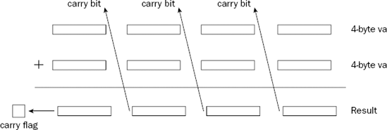
As shown in Figure 8-1, when the lowest value data element pair is added, the carry flag bit must be carried to the next value data element pair, and so on up to the last data element pair.
To do this manually, you would have to use a combination of ADD and JC (or JO) instructions, producing a complicated web of instructions for determining when a carry (or overflow) condition was present, and when it needed to be added to the next addition operation. Fortunately, you do not have to deal with this, as Intel provides a simple solution.
The ADC instruction can be used to add two unsigned or signed integer values, along with the value contained in the carry flag from a previous ADD instruction. To add multiple groups of bytes, you can chain together multiple ADC instructions, as the ADC instruction also sets the carry and overflow flags as appropriate for the operation. This is shown in Figure 8-2.

The format of the ADC instruction is
adc source, destination
where source can be an immediate value or an 8-, 16-, or 32-bit register or memory location value, and destination can be an 8-, 16-, or 32-bit register or memory location value. (Similar to the ADD instruction, source and destination cannot both be memory locations at one time). Also, as with the ADD instruction, the GNU assembler requires an additional character in the mnemonic to indicate the size of the operands (b, w, or l).
To demonstrate using the ADC instruction, let's write a program to add two large numbers, 7,252,051,615 and 5,732,348,928. Since they are both larger than the limit of the 32-bit unsigned integer, we must use a 64-bit unsigned integer value, using two 32-bit registers to hold the value. Because two registers are used to hold the 64-bit value, they must be added separately as two 32-bit additions. After the low-order 32-bits are added, if a carry bit is present, it must be added to the upper 32-bit addition. This can be done using the ADC instruction.
To start off, we need to determine which registers will be used to contain the 64-bit values, and how they will be added. This is shown in Figure 8-3.
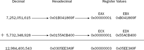
As shown in Figure 8-3, the EAX:EBX register combination holds the first value, while the ECX:EDX register combination holds the second value. To add the 64-bit values, first the EBX and EDX registers must be added using the ADD instruction. As you can see from the values in the EBX and EDX registers, the addition will produce a carry bit. Following that, the EAX and ECX registers are added, along with the carry bit from the first addition.
The adctest.s program demonstrates how to implement this operation. It adds two 64-bit values, one held in the EAX:EBX register combination and the other in the ECX:EDX register combination:
# adctest.s - An example of using the ADC instruction
.section .data
data1:
   .quad 7252051615
data2:
   .quad 5732348928
output:
   .asciz "The result is %qd
"
.section .text
.globl _start
_start:
   movl data1, %ebx
   movl data1+4, %eax
   movl data2, %edx
   movl data2+4, %ecx
   addl %ebx, %edx
   adcl %eax, %ecx
   pushl %ecx
   pushl %edx
   push $output
   call printf
   addl $12, %esp
   pushl $0
   call exit
The adctest.s program first defines two 64-bit integer values that will be added together, along with the text for the printf function:
data1:
   .quad 7252051615
data2:
   .quad 5732348928
output:
   .asciz "The result is %qd
"
The %qd parameter is used in the printf function to display 64-bit signed integer values (if you just use the standard %d parameter it will only use a 32-bit value). The 64-bit values are loaded into the EAX:EBX and ECX:EDX register pairs using indexed addressing:
movl data1, %ebx
movl data1+4, %eax
movl data2, %edx
movl data2+4, %ecx
The low 32-bits of the data1 value are loaded into the EBX register, and the high 32-bit value is loaded into the EAX register. The same procedure is used to load the data2 value into the ECX:EDX register pair.
After all that, the addition is performed in two instructions:
addl %ebx, %edx
adcl %eax, %ecx
The ADDL instruction is used to add the two low-order registers, and then the ADCL instruction is used to add the two high-order registers, along with the carry flag. This ensures that if the low-order registers overflow, it will be caught and added to the high-order registers.
After the addition, the 64-bit result will be in the ECX:EDX register pair. To use them in the printf function, you must push them onto the stack, with the register containing the high-order bytes (ECX) first. The combination of the ECX and EDX pair will be read by the C printf function as a single 64-bit value.
After assembling and linking the file, you can directly display the output, or run the debugger to watch the various steps along the process. For example, after the registers are loaded with the operands, but before the addition takes place, the registers should look like this:
(gdb) info reg
eax            0x1      1
ecx            0x1      1
edx            0x55acb400       1437381632
ebx            0xb041869f       −1337882977
The hex values of the 64-bit integers have been loaded into the registers as planned. The debugger assumes the register values are signed integers, so the third column values will be meaningless. After the addition instructions, you can look at the registers again:
(gdb) info reg
eax            0x1      1
ecx            0x3      3
edx            0x5ee3a9f        99498655
ebx            0xb041869f       −1337882977
The ECX:EDX register pair contains the result information, as shown in Figure 8-3. The result is also displayed using the printf function in decimal form:
$ ./adctest1
The result is 12984400543
$
You can play around with the values in the data1 and data2 variables, changing them and watching how the registers are loaded during the program execution. You can change them to negative values as well, and still come up with the correct results (because the ADD and ADC instruction work with signed integers as well as unsigned integers).
Now that you have integer addition under your belt, integer subtraction should be a breeze. The following sections describe the ins and outs of integer subtraction in assembly language.
The basic form for subtraction is the SUB instruction. Just like the ADD instruction, it can be used to subtract both unsigned and signed integers. The format of the SUB instruction is
sub source, destination
where the source value is subtracted from the destination value, with the result stored in the destination operand location. The source and destination operands can be 8-, 16-, or 32-bit registers or values stored in memory (but again, they cannot both be memory locations at the same time). The source value can also be an immediate data value.
As with the ADD instruction, the GNU assembler requires a size character to be added to the mnemonic. The usual characters apply (b for byte, w for word, and l for doubleword).
The subtest.s program demonstrates using the SUB instruction in an assembly language program:
# subtest1.s - An example of the SUB instruction
.section .data
data:
   .int 40
.section .text
.globl _start
_start:
   nop

   movl $0, %eax
   movl $0, %ebx
   movl $0, %ecx
   movb $20, %al
   subb $10, %al
   movsx %al, %eax
   movw $100, %cx
   subw %cx, %bx
   movsx %bx, %ebx
   movl $100, %edx
   subl %eax, %edx
   subl data, %eax
   subl %eax, data
   movl $1, %eax
   movl $0, %ebx
   int $0x80
The subtest1.s program performs various basic subtractions using immediate values, registers, and memory locations. After assembling the program, you can watch the registers and memory location in the debugger as it is running. Note the values as the SUB instructions are executed. Note particularly the last SUB instruction, which subtracts the value in the EAX register (−30) from the value at the data1 memory location (40):
(gdb) print $eax
$1 = −30
(gdb) x/d &data
0x80490ac <data>:       40
(gdb) s
_start () at subtest1.s:23
23         movl $1, %eax
(gdb) x/d &data
0x80490ac <data>:       70
(gdb)
The processor subtracted −30 from 40, and got the correct answer, 70.
It is extremely important to remember the order of the
SUBinstruction for the GNU assembler. Using the Intel syntax will produce the wrong results!
A close relative of the SUB instruction is the NEG instruction. It produces the two's complement of a value. This is the same as using the SUB instruction to subtract the value from zero, but quicker.
Similar to the ADD instruction, the SUB instruction modifies several of the EFLAGS register bits after it performs the subtraction operation. However, the concept of carry and overflow are different in subtraction.
In addition, the carry flag is set when the addition result is too large of a positive value for the data size used to hold the operands. Obviously, with subtraction, the problem arises when the subtraction result becomes too large of a negative value for the data size.
For example, with unsigned integers, what happens when you subtract 5 from 2? The subtest2.s program demonstrates this problem:
# subtest2.s - An example of a subtraction carry
.section .text
.globl _start
_start:
   nop
   movl $5, %eax
   movl $2, %ebx
   subl %eax, %ebx
   jc under
   movl $1, %eax
   int $0x80
under:
   movl $1, %eax
   movl $0, %ebx
   int $0x80
The subtest2.s program simply places the 5 value in the EAX register, and the 2 value in the EBX register, and then subtracts the EAX register from the EBX register. The JC instruction is used to jump if the carry flag is set. The result code from the program will be either the subtraction value or a 0 if the carry flag is set.
After assembling the program, run it and see what happens:
$ ./subtest2
$ echo $?
0
$
The carry flag was set when the result was less than zero (which is invalid in unsigned integers). However, by examining the value of the EBX register in the debugger, you should see something interesting:
(gdb) print $ebx
$1 = −3
(gdb)
The EBX register contained the correct value, even though it was "supposed" to be unsigned. The processor does not know if you are using unsigned or signed integers. It is up to your program to determine when a value is outside of the range of the unsigned (or signed) values.
The carry flag is used to determine when subtracting unsigned integers produces a negative result.
As with adding signed integers, if you are subtracting signed integers, the carry flag is not useful, as the result can often be negative. Instead, you must rely on the overflow flag to tell you when you have reached the data size limits. This is demonstrated in the subtest3.s program:
# subtest3.s - An example of an overflow condition in a SUB instruction
.section .data
output:
   .asciz "The result is %d
"
.section .text
.globl _start
_start:
   movl $-1590876934, %ebx
   movl $1259230143, %eax
   subl %eax, %ebx
   jo over
   pushl %ebx
   pushl $output
   call printf
   add  $8, %esp
   pushl $0
   call exit
over:
   pushl $0
   pushl $output
   call printf
   add  $8, %esp
   pushl $0
   call exit
The subtest3.s program demonstrates subtracting a positive value stored in the EAX register from a negative value stored in the EBX register, producing a value too large for the 32-bit EBX register. The JO instruction is used to detect the overflow flag, and send the program to the over: label, setting the output value to 0. After assembling the program and linking it with the C libraries, you can run it to see the output:
$ ./subtest3
The result is 0
$
The overflow condition was detected and the JO instruction was executed and followed. You can test to determine whether the opposite condition works by changing the value assigned to the EAX to a negative value:
movl $-1259230143, %eax
and running the program again:
$ ./subtest3
The result is −331646791
$
This time, subtracting a negative number produced a smaller negative number, well within the data size limits, and not setting the overflow flag.
Just like in addition, you can use the carry condition to your advantage to subtract large signed integer values. The SBB instruction utilizes the carry and overflow flags in multibyte subtractions to implement the borrow feature across data boundaries.
The format of the SBB instruction is
sbb source, destination
where the carry bit is added to the source value, and the result is subtracted from the destination value. The result is stored in the destination location. As usual, the source and destination values can be 8-, 16-, or 32-bit registers or values in memory, and of course you can't use memory locations for both the source and destination values at the same time.
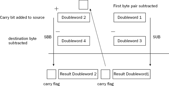
The SBB instruction is most often used to "scoop up" the carry flag from a previous SUB instruction. When the previous SUB instruction is executed and a carry results, the carry bit is "borrowed" by the SBB instruction to continue the subtraction on the next data pair. This is demonstrated in Figure 8-4.
The following sbbtest.s program demonstrates using the SBB instruction in a multibyte subtraction problem:
# sbbtest.s - An example of using the SBB instruction
.section .data
data1:
   .quad 7252051615
data2:
   .quad 5732348928
output:
   .asciz "The result is %qd
"
.section .text
.globl _start
_start:
   nop
   movl data1, %ebx
   movl data1+4, %eax
   movl data2, %edx
   movl data2+4, %ecx
   subl %ebx, %edx
   sbbl %eax, %ecx
   pushl %ecx
   pushl %edx
   push $output
   call printf
   add  $12, %esp
   pushl $0
   call exit
You may notice that the sbbtest.s program looks exactly like the adctest.s program except for the use of the SUB and SBB instructions instead of the ADD and ADC instructions. Two quadword values are defined, loaded into registers, and then subtracted using the SUB/SBB combination.
After assembling the program and linking it with the C libraries, you should get the following result:
$ ./sbbtest
The result is −1519702687
$
You can play around with the values of the data1 and data2 quadwords to make sure that this works for any combination of valid 64-bit values.
Often, when you are creating assembly language programs, you must step through a data array to process each element. This is so common of an occurrence in the programming field that Intel provided special instructions for automatically providing a counting function.
The INC and DEC instructions are used to increment (INC) and decrement (DEC) an unsigned integer value. The INC and DEC instructions don't affect the carry flag, so you can increment or decrement a counter value without affecting any other additions or subtractions in a programming loop involving carry operations.
The format of the instructions is
dec destination
inc destination
where destination can be an 8-, 16-, or 32-bit register or value in memory.
Remember that the
INCandDECinstructions are mainly used for unsigned integers. If you decrement a 32-bit register that is set to 0, the new value will be0xFFFFFFFF, which may look like −1 as a signed integer, but it is treated like 4294967295 as an unsigned integer (the proper flags will not be set). If you use them for signed integers, be careful of the sign changes.
One of the more complicated functions in integer arithmetic is multiplication. Unlike addition and subtraction, multiplication requires separate instructions for operating on unsigned and signed integers. This section shows the instructions for multiplying integers, and how to use them in your programs.
The MUL instruction is used to multiply two unsigned integers. Its format is somewhat different from what you would expect. The format for the MUL instruction is
mul source
where source can be an 8-, 16-, or 32-bit register or memory value. You might be wondering how you can multiply two values by only supplying one operand in the instruction line. The answer is that the destination operand is implied.
Working with the implied destination operand is somewhat complicated. For one thing, the destination location always uses some form of the EAX register, depending on the size of the source operand. Thus, one of the operands used in the multiplication must be placed in the AL, AX, or EAX registers, depending on the size of the value.
Due to the large values that can result from the multiplication, the destination location of the MUL instruction must be twice the size of the source operand. If the source value is 8 bits, the destination operand is the AX register, as the result is 16 bits. It gets even more complicated when the source operand is larger.
Unfortunately, when multiplying a 16-bit source operand, the EAX register is not used to hold the 32-bit result. In order to be backwardly compatible with older processors, Intel uses the DX:AX register pair to hold the 32-bit multiplication result value (this format started back in the 16-bit processor days). The high-order word of the result is stored in the DX register, while the low-order word is stored in the AX register.
For 32-bit source values, the 64-bit EDX:EAX register pair is used, again with the high-order doubleword in the EDX register, and the low-order doubleword in the EAX. Make sure that if you have data stored in the EDX (or DX) register that you save it elsewhere when using the 16- or 32-bit versions of MUL.
To help sum this up, the following table outlines the unsigned integer multiplication requirements.
Source Operand Size | Destination Operand | Destination Location |
|---|---|---|
8 bits | AL | AX |
16 bits | AX | DX:AX |
32 bits | EAX | EDX:EAX |
Also, it is important to remember that with the GNU assembler, you must append the correct size character to the end of the mnemonic.
As an example of using the MUL instruction, let's compute 315,814 times 165,432. Figure 8-5 demonstrates how these values will be handled by the MUL instruction.
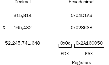
The two operands used in the MUL instruction are both 32-bit values. The result of the multiplication is stored as a 64-bit value, split in the EDX and the EAX registers.
The multest.s program demonstrates multiplying the two 32-bit unsigned integers, and retrieving the result from the EDX:EAX registers:
# multest.s - An example of using the MUL instruction
.section .data
data1:
   .int 315814
data2:
   .int 165432
result:
   .quad 0
output:
   .asciz "The result is %qd
"
.section .text
.globl _start
_start:
   nop
   movl data1, %eax
   mull data2
   movl %eax, result
   movl %edx, result+4
   pushl %edx
   pushl %eax
   pushl $output
   call printf
   add $12, %esp
   pushl $0
   call exit
The multest.s program defines the two integer values in memory (remember that when using the MUL instruction, they must be unsigned values), loads one of them into the EAX register, and then uses the MUL instruction to multiple the other one with the EAX register. The result from the EDX:EAX register pair is both loaded into a 64-bit memory location (using indexed memory access) and displayed using the printf C function.
After assembling the program and linking it with the C library, you can run it directly to see the output, and run it in the debugger to watch the registers in action. The debugger output after the MUL instruction should look something like the following:
(gdb) print/x $eax
$3 = 0x2a16c050
(gdb) print/x $edx
$4 = 0xc
(gdb) x/gd &result
0x80491c4 <result>:     52245741648
(gdb) x/8b &result
0x80491c4 <result>: 0x50  0xc0  0x16  0x2a  0x0c  0x00 0x00 0x00
(gdb)
The EDX:EAX register pair combine to produce the resulting value, which is stored in the result memory location, and displayed by the printf function.
While the MUL instruction can only be used for unsigned integers, the IMUL instruction can be used by both signed and unsigned integers, although you must be careful that the result does not use the most significant bit of the destination. For larger values, the IMUL instruction is only valid for signed integers. To complicate things even more, there are three different instruction formats of the IMUL instruction.
The first format of the IMUL instruction takes one operand, and behaves exactly the same as the MUL instruction:
imul source
The source operand can be an 8-, 16-, or 32-bit register or value in memory, and it is multiplied with the implied operand located in the AL, AX, or EAX registers (depending on the source operand size). The result is then placed in the AX register, the DX:AX register pair, or the EDX:EAX register pair.
The second format of the IMUL instruction enables you to specify a destination operand other than the EAX register:
imul source, destination
where source can be a 16- or 32-bit register or value in memory, and destination must be a 16- or 32-bit general-purpose register. This format enables you to specify where the result of the multiplication will go (instead of being forced to use the AX and DX registers).
The downside to this format is that the multiplication result is forced into the size of the single destination register (no 64-bit results). Extreme care must be taken when using this format that you do not overflow the destination register (check the carry or overflow flags using the standard methods shown in Chapter 6, "Controlling Execution Flow," after the multiplication to ensure that the result fits in the destination register).
The third format of the IMUL instruction enables you to specify three operands:
imul multiplier, source, destination
where multiplier is an immediate value, source is a 16- or 32-bit register or value in memory, and destination must be a general-purpose register. This format enables you to perform a quick multiplication of a value (the source) with a signed integer (the multiplier), storing the result in a general-purpose register (the destination).
Just like the
MULinstruction, remember to add the size character to the end of theIMULmnemonic when using it in the GNU assembler to specify the size of the source and destination operands.
The first format of the IMUL instruction is somewhat trivial once you are comfortable with the MUL instruction. The other two formats may need some examples, so here's the imultest.s program, which demonstrates the last two IMUL instruction formats:
# imultest.s - An example of the IMUL instruction formats
.section .data
value1:
   .int 10
value2:
   .int −35
value3:
   .int 400
.section .text
.globl _start
_start:
   nop
   movl value1, %ebx
   movl value2, %ecx
   imull %ebx, %ecx
   movl value3, %edx
   imull $2, %edx, %eax
   movl $1, %eax
   movl $0, %ebx
   int $0x80
The imultest.s program creates some signed integer values to work with (value1, value2, and value3), moves them into registers, and performs some multiplication using the various IMUL instruction formats.
After assembling and linking the program, you can use the debugger to watch the register values during the program. After stepping through the IMUL instructions, the registers should look like this:
(gdb) info reg
eax            0x320    800
ecx            0xfffffea2       −350
edx            0x190    400
ebx            0xa      10
The EAX register contains the value of EDX (400) multiplied by the immediate value 2. The ECX register contains the value of the EBX register (10) multiplied by the value originally loaded into the ECX register (-35). Notice that the result was placed in the ECX register as a signed integer value.
Remember that when using signed integers and the IMUL instruction, it is important to always detect overflows in the result. One way to do this is to check the overflow flag using the JO instruction (the other way is to check the carry flag).
The imultest2.s program demonstrates this:
# imultest2.s - An example of detecting an IMUL overflow
.section .text
.globl _start
_start:
   nop
   movw $680, %ax
   movw $100, %cx
   imulw %cx
   jo over
   movl $1, %eax
   movl $0, %ebx
   int $0x80
over:
   movl $1, %eax
   movl $1, %ebx
   int $0x80
The imultest2.s program moves two values into 16-bit registers (AX and CX), and then uses the 16-bit IMUL instruction to multiply them. The result is set so that it will overflow the 16-bit register, and the JO instruction jumps to the over label, which exits the program with a result code of 1. If you modify the immediate data values loaded into the registers so the result is less than 65,535, the overflow flag is not set by the IMUL instruction, the JO instruction is not executed, and the program exits with a result code of 0.
Similar to multiplication, division requires using a specific instruction depending on whether you are using unsigned or signed integers. The tricky part about integer division is that the answer is not always an exact integer, such as if you divide 9 by 2. This produces two parts to the answer. The quotient is the number of times the divisor goes into the dividend. The remainder is how much is left over (the fractional part of the answer). The division instructions produce both the quotient and remainder parts as results of the division.
This section describes and demonstrates the DIV and IDIV instructions used for integer division.
The DIV instruction is used for dividing unsigned integers. The format of the DIV instruction is
div divisor
where divisor is the value that is divided into the implied dividend, and can be an 8-, 16-, or 32-bit register or value in memory. The dividend must already be stored in the AX register (for a 16-bit value), the DX:AX register pair (for a 32-bit value), or the EDX:EAX register pair (for a 64-bit value) before the DIV instruction is performed.
The maximum value allowed for the divisor depends on the size of the dividend. For a 16-bit dividend, the divisor can only be 8 bits, for a 32-bit dividend 16 bits, and for a 64-bit dividend the divisor can only be 32 bits.
The result of the division is two separate numbers: the quotient and the remainder. Both values are stored in the same registers used for the dividend value. The following table shows how this is set up.
Dividend | Dividend Size | Quotient | Remainder |
|---|---|---|---|
AX | 16 bits | AL | AH |
DX:AX | 32 bits | AX | DX |
EDX:EAX | 64 bits | EAX | EDX |
This means that you will lose the value of the dividend when the division completes, so make sure that this is not your only copy of the value (or that you don't care about the value of the dividend after the division). Also remember that the result will alter the value of the DX or EDX registers, so be careful what is stored there as well.
The divtest.s program demonstrates a simple division example:
# divtest.s - An example of the DIV instruction
.section .data
dividend:
   .quad 8335
divisor:
   .int 25
quotient:
   .int 0
remainder:
   .int 0
output:
   .asciz "The quotient is %d, and the remainder is %d
"
.section .text
.globl _start
_start:
   nop
   movl dividend, %eax
   movl dividend+4, %edx
   div1 divisor
   movl %eax, quotient
   movl %edx, remainder
   pushl remainder
   pushl quotient
   pushl $output
   call printf
   add  $12, %esp
   pushl $0
   call exit
The divtest.s program loads a 64-bit quadword integer into the EDX:EAX register pair (remember the little-endian order in memory versus the big-endian order in registers, discussed in Chapter 5, "Moving Data"), and divides that value by a 32-bit doubleword integer value stored in memory. The 32-bit quotient value is stored in one memory location, and the 32-bit remainder value is stored in another memory location.
After assembling the program and linking it with the C library, you can run it using different values of the dividend and divisor (remember these must be positive values, and less than the maximum allowed values for their data sizes). You can watch how the values are manipulated in the registers using the debugger.
The IDIV instruction is used exactly like the DIV instruction, but for dividing signed integers. It too uses an implied dividend, located in the AX register, the DX:AX register pair, or the EDX:EAX register pair.
Unlike the IMUL instruction, there is only one format for the IDIV instruction, which specifies the divisor used in the division:
idiv divisor
where divisor can again be an 8-, 16-, or 32-bit register or value in memory.
The IDIV instruction returns the results using the same registers as the DIV instruction, and in the same format of quotient and remainder (except that the results are signed integers).
For signed integer division, the sign of the remainder is always the sign of the dividend.
Another thing to remember about signed division is the size of the dividend. Because it must be twice the size of the divisor, sometimes you must extend the integer value to the proper data size (see Chapter 7). It is important to use the sign extension instructions (such as MOVSX) to extend the dividend to the proper data size for the division. Failure to do so will corrupt the dividend value and produce errors in your results.
The biggest problem with integer division is detecting when an error condition has occurred, such as when a division by zero happens, or the quotient (or remainder) overflows the destination register.
When an error occurs, the system produces an interrupt, which will produce an error on the Linux system, such as the following:
$ ./divtest
Floating point exception
$
This error was produced by setting the divisor value in the divtest.s program to 0.
It is your responsibility to check the divisor and dividend values before performing the DIV or IDIV instructions in your programs. Not doing so can result in erratic behavior in your applications.
Multiplying and dividing are two of the most time-consuming operations on the processor. However, there are some tricks that you can use to help speed things up. The shift instructions provide a quick and easy way to perform multiplication and division based on powers of 2. This section describes the methods used to perform multiplication and division using the shift instructions.
Shifting utilizes a feature of binary arithmetic that makes multiplying and dividing by powers of 2 simple. You are probably familiar with the decimal world, and how shifting a decimal value into another decimal place automatically multiplies or divides it by a power of 10 (for example, moving the value 2 over one decimal place to 20 is the same as multiplying it by 10).
The same principle applies to binary numbers, except using powers of 2. Shifting a binary number to the left one space multiplies it by 2, two spaces multiplies it by 4, three spaces multiplies it by 8, and so on. Shifting bits in a data element is much quicker than performing binary multiplication and can be used to increase the performance of mathematically intensive programs.
The following sections describe how to implement the shift instructions in your programs.
To multiply integers by a power of 2, you must shift the value to the left. Two instructions can be used to left shift integer values, SAL (shift arithmetic left) and SHL (shift logical left). Both of these instructions perform the same operation, and are interchangeable. They have three different formats:
sal destination
sal %cl, destination
sal shifter, destination
The first format shifts the destination value left one position, which is the equivalent of multiplying the value by 2.
The second format shifts the destination value left by the number of times specified in the CL register.
The final version shifts the destination value left the number of times indicated by the shifter value. In all formats, the destination operand can be an 8-, 16-, or 32-bit register or value in memory.
As always, the GNU assembler requires the usual one-character letter appended to the mnemonic to indicate the size of the destination value.
The shift left instructions can be performed on both signed and unsigned integers. The bits emptied by the shift are filled with zeroes. Any bits that are shifted out of the data size are first placed in the carry flag, and then dropped in the next shift. Thus, if a value contains a 1 value in the most significant bit, and is shifted left twice, the most significant bit will be dropped from the carry flag. This is demonstrated in Figure 8-6.

The saltest.s program demonstrates the basics of using the SAL instruction:
# saltest.s - An example of the SAL instruction
.section .data
value1:
   .int 25
.section .text
.globl _start
_start:
   nop
   movl $10, %ebx
   sall %ebx
   movb $2, %cl
   sall %cl, %ebx
   sall $2, %ebx
   sall value1
   sall $2, value1
   movl $1, %eax
   movl $0, %ebx
   int $0x80
The saltest.s program demonstrates all three formats of the SAL instruction, using the EBX register to hold the value to shift. After assembling the program, you can use the debugger to watch the register values:
(gdb) info reg
eax            0x0      0
ecx            0x2      2
edx            0x0      0
ebx            0x140    320
(gdb) x/d &value1
0x804909c <value1>:     200
(gdb)
To follow along, the decimal value 10 is loaded into the EBX register. The first SAL instruction shifts it one place (multiplying by 2, making 20). The second SAL instruction shifts it two places (multiplying by four, making 80), and the third SAL instruction shifts it two more places (multiplying by four, making 320). The value in the value1 location (25) is shifted one place (making it 50), and then shifted two more places (making 200).
Dividing by shifting involves shifting the binary value to the right. However, as you shift an integer value to the right, you must pay attention to the sign of the integer.
For unsigned integers, the bits to the left that are emptied can be filled with zeroes without any problems. Unfortunately, with signed integers, a negative number will be adversely affected by zero-filling the leading bits.
To solve this problem there are two right-shift instructions. The SHR instruction clears the bits emptied by the shift, which makes it useful only for shifting unsigned integers. The SAR instruction either clears or sets the bits emptied by the shift, depending on the sign bit of the integer. For negative numbers, the bits are set to 1, but for positive numbers, they are cleared to zero.
As with the left-shift instructions, the right-shift instructions shift bits out of the data element. Any bits shifted out of the data element (the least significant bits) are first moved to the carry flag, and then shifted out (lost). This is demonstrated in Figure 8-7.

Close relatives to the shift instructions are the rotate instructions. The rotate instructions perform just like the shift instructions, except the overflow bits are pushed back into the other end of the value instead of being dropped. For example, a left rotate of a byte value takes the value in bit position 7 and places it in bit position 0, with each of the other bit positions shifted one place left.
The following table shows the various rotate instructions that can be used.
Instruction | Description |
|---|---|
Rotate value left | |
Rotate value right | |
Rotate left and include carry flag | |
Rotate right and include carry flag |
The last two instructions use the carry flag as an additional bit position, to allow 9-bit shifting. The formats of the rotate instructions are the same as the shift instructions, providing three options for their use:
A single operand that is shifted once in the indicated direction
Two operands: The
%clregister to indicate the number of times to rotate and the destination operandTwo operands: An immediate value to indicate the number of times to rotate and the destination operand
As described in Chapter 7, Binary Coded Decimal (BCD) format is a popular method to handle human-readable numbers, and quickly process them in the processor. Although much of the advanced BCD-handling operations are located in the FPU, the core processor contains some simplistic instructions for performing arithmetic using BCD values.
This section describes the basic BCD arithmetic instructions available, and demonstrates how they are used within the assembly language program.
As described in Chapter 7, unpacked BCD values contain a single decimal digit (0 through 9) in a byte. Multiple decimal digits are stored in multiple bytes, 1 byte per digit. When an application is required to perform a mathematical operation on the unpacked BCD values, it is assumed that the result should also be in unpacked BCD format. Fortunately, the IA-32 platform provides special instructions for producing unpacked BCD results from common mathematical operations.
Four instructions are used to convert binary arithmetic results to unpacked BCD format:
AAA: Adjusts the result of an addition process
AAS: Adjusts the result of a subtraction process
AAM: Adjusts the result of a multiplication process
AAD: Prepares the dividend of a division process
These instructions must be used in combination with the normal unsigned integer ADD, ADC, SUB, SBB, MUL, and DIV instructions. The AAA, AAS, and AAM instructions are used after their respective operation to convert a binary result into unpacked BCD format. The AAD instruction is somewhat different in that it is used before the DIV instruction to prepare the dividend value to produce an unpacked BCD result.
Each of these instructions uses an implied operand, the AL register. The AAA, AAS, and AAM instructions assume that the previous operation result is placed in the AL register, and converts that value to unpacked BCD format. The AAD instruction assumes that the dividend value is placed in the AX register in unpacked BCD format, and converts it to binary format for the DIV instruction to handle. The result is a proper unpacked BCD value, the quotient in the AL register, and the remainder in the AH register (in unpacked BCD format).
When working with multibyte unpacked BCD values, the carry and overflow flags must be used to ensure that the proper values are calculated. Figure 8-8 demonstrates this problem.

The addition performed on the first unpacked BCD values produces a carry, which must be carried to the next BCD value to create the proper result. The AAA, AAS, and AAM instructions all use the AH register along with the carry flag to indicate when a carry operation is required.
This is best shown in a sample program. The aaatest.s program demonstrates adding two multibyte unpacked BCD values:
# aaatest.s - An example of using the AAA instruction
.section .data
value1:
   .byte 0x05, 0x02, 0x01, 0x08, 0x02
value2:
   .byte 0x03, 0x03, 0x09, 0x02, 0x05
.section .bss
   .lcomm sum, 6
.section .text
.globl _start
_start:
   nop
   xor %edi, %edi
   movl $5, %ecx
   clc
loop1:
   movb value1(, %edi, 1), %al
   adcb value2(, %edi, 1), %al
   aaa
   movb %al, sum(, %edi, 1)
   inc %edi
   loop loop1
   adcb $0, sum(, %edi, 4)
   movl $1, %eax
   movl $0, %ebx
   int $0x80
The unpacked BCD values are stored in memory locations in little-endian format. The first value is read into the AL register 1 byte at a time, and added with the same place value of the second value using the ADC instruction. The ADC instruction is used to ensure that any carry bits are added from the previous additions (don't forget the CLC instruction before the loop to ensure that the carry flag is cleared). The AAA instruction is used after the ADC instruction to convert the binary result in the AL register to unpacked BCD format before it is stored in the same place value location in the sum location. The ECX register is used to count the value places so the LOOP instruction knows when to quit.
After assembling the program, you can test it by running it through the debugger and watching what happens during each step in the process. For example, after the third time the ADC instruction is executed (the third value place), the AL register contains the value
(gdb) info reg
eax            0xa      10
(gdb)
which shows that the binary addition of the 9 and 1 is 10. However, after the AAA instruction is executed, the AX register has the value
(gdb) info reg
eax            0x100    256
(gdb)
which shows the unpacked value 1 in the AH register, and 0 in the AL register. The 1 is carried to the next place value addition. In the end, the result is placed in the sum memory location in unpacked BCD format:
(gdb) x/6b &sum
0x80490b8 <sum>:        0x08    0x05    0x00    0x01    0x08    0x00
(gdb)
Thus, the addition of 28,125 and 52,933 is 81,058.
When working with packed BCD values, only two instructions are available for use:
DAAAdjusts the result of theADDorADCinstructionsDASAdjusts the result of theSUBorSBBinstructions
These instructions perform the same functions as the AAA and AAS instructions, but with packed BCD values. They also use the implied operand located in the AL register, and place the result of the conversion in the AL register, with the carry bit placed in the AH register and the auxiliary carry flag bit.
An example of packed BCD arithmetic is shown in Figure 8-9.

The packed BCD value 52,933 is loaded into memory using little-endian format (0x332905), and has the BCD value 28,125 (0x258102) subtracted from it. The result in packed BCD format is 0x084802.
The dastest.s program demonstrates performing the subtraction using the SBB and DAS instructions:
# dastest.s - An example of using the DAS instruction
.section .data
value1:
   .byte 0x25, 0x81, 0x02
value2:
   .byte 0x33, 0x29, 0x05
.section .bss
   .lcomm result, 4
.section .text
.globl _start
_start:
   nop
   xor %edi, %edi
   movl $3, %ecx
loop1:
   movb value2(, %edi, 1), %al
   sbbb value1(, %edi, 1), %al
   das
   movb %al, result(, %edi, 1)
   inc %edi
   loop loop1
   sbbb $0, result(, %edi, 4)
   movl $1, %eax
   movl $0, %ebx
   int $0x80
The dastest.s program loads the first packed BCD value into the AL register (one decimal place at a time), and subtracts the second packed BCD value from it using the SBB instruction. This way, any carry bits left over from the previous subtraction are accounted for. The DAS instruction is then used to convert the result into packed BCD format to store in the result memory location. The ECX register is used to control the number of times the process must be looped through (once for each packed BCD byte). After the conversion, if there is a left-over carry bit, it is placed in the result value.
After assembling and linking the program, you can run it in the debugger and watch the EAX register value as the subtraction values are computed by the SBB instruction, and then changed to packed BCD format by the DAS instruction. For example, after the first subtraction, the EAX register has the following value:
(gdb) info reg
eax            0x0e       14
(gdb)
But after the DAS instruction is executed, the value is changed to
(gdb) info reg
eax           0x08          8
(gdb)
which represents the first decimal place of the result.
Besides the standard arithmetic functions of addition, subtraction, multiplication, and division, assembly language also provides instructions to perform various operations on the raw bits contained in the byte values. This section looks at two common types of bit functions that assembly programmers often use: Boolean logic and bit testing.
When working with binary numbers, it is handy to have the standard Boolean logic functions available. The following Boolean logic operations are provided:
ANDNOTORXOR
The AND, OR, and XOR instructions use the same format:
and source, destination
where source can be an 8-, 16-, or 32-bit immediate value, register, or value in memory, and destination can be an 8-, 16-, or 32-bit register or value in memory (but as usual, you cannot use memory values for both the source and destination). The NOT instruction uses a single operand, which is both the source value and location of the destination result.
The Boolean logic functions perform bit-wise operations on the source and destination. That is, each bit of the data elements is compared individually in order, using the logic function specified. You have already seen some examples of using Boolean logic instructions in assembly language programs. Several example programs used the XOR instruction to zero the value of a register. The most efficient way to clear out a register is to exclusive OR the register with itself using the XOR instruction. Each bit that was set to 1 when XOR'd with itself becomes 0, and each bit that was set to 0 when XOR'd with itself also becomes 0. This ensures that all of the bits in the register will be set to 0, faster than what it would take to load the immediate value of 0 using the MOV instruction.
Sometimes it is necessary to determine whether a single bit within a value is set or not. The most common use for this feature is when checking the values of the EFLAGS register flags. Instead of trying to compare the value of the entire register, it would be nice to detect the value of a single flag.
One way to do this is to use the AND instruction, comparing the EFLAGS register to a known bit value to single out the bit(s) you want to check. However, you may not want to alter the value of the register containing the EFLAGS bits.
To solve this problem, the IA-32 platform provides the TEST instruction. The TEST instruction performs a bit-wise logical AND between two 8-, 16-, or 32-bit values, and sets the sign, zero, and parity flags accordingly, without modifying the destination value.
The format of the TEST instruction is the same as for the AND instruction. Even though no data is written to the destination location, you still must specify any immediate values as the source value. This is similar to how the CMP instruction works like the SUB instruction, but it does not store the result anywhere.
As mentioned, the most common use of the TEST instruction is to check for flags in the EFLAGS register. For example, if you want to use the CPUID instruction to check processor properties, you should first ensure that the processor supports the CPUID instruction.
The ID flag in the EFLAGS register (bit 21) is used to determine whether the CPUID instruction is supported by the processor. If the ID flag can be modified, the CPUID instruction is available. To test this, you must retrieve the EFLAGS register, invert the ID flag bit, and then test to see if it was really changed. The cpuidtest.s program performs these functions:
# cpuidtest.s - An example of using the TEST instruction
.section .data
output_cpuid:
   .asciz "This processor supports the CPUID instruction
"
output_nocpuid:
   .asciz "This processor does not support the CPUID instruction
"
.section .text
.globl _start
_start:
   nop
   pushfl
   popl %eax
   movl %eax, %edx
   xor $0x00200000, %eax
   pushl %eax
   popfl
pushfl
   popl %eax
   xor %edx, %eax
   test $0x00200000, %eax
   jnz cpuid
   pushl $output_nocpuid
   call printf
   add  $4, %esp
   pushl $0
   call exit
cpuid:
   pushl $output_cpuid
   call printf
   add  $4, %esp
   pushl $0
   call exit
The cpuidtest.s program first saves the value of the EFLAGS register to the top of the stack using the PUSHFL instruction. Next, the POPL instruction is used to retrieve the EFLAGS value into the EAX register.
The next step demonstrates how the XOR instruction is used to set a bit in a register. A copy of the EFLAGS value is saved into the EDX register using the MOVL instruction, and then the XOR instruction is used to set the ID bit (still in the EAX register) to a one value. The XOR instruction uses an immediate data value set to the bit setting of the ID bit. When exclusive-OR'd with the EAX register value, it ensures that the ID bit is set to one. The next step is to push the new EAX register value onto the stack, and use the POPFL instruction to store it in the EFLAGS register.
Now you must determine whether setting the ID flag worked. Again, the PUSHFL instruction is used to push the EFLAGS register onto the stack, and the POPL instruction is used to pop it into the EAX register. The value is XOR'd with the original EFLAGS value (stored in EDX earlier) to see what values have changed.
Finally, the TEST instruction is used to see if the ID flag bit changed. If so, the value in EAX will not be zero, and the JNZ instruction jumps to print out the appropriate message.
A lot ground was covered in this chapter. The basics of integer arithmetic were discussed, showing how to perform basic addition, subtraction, multiplication, and division with both unsigned and signed integers.
The ADD and ADC instructions are used to add both unsigned and signed integers, with the ADC instruction used to include the carry flag for multibyte values. The SUB and SBB instructions are used to subtract unsigned and signed integers, with the SBB instruction used to include the carry flag for multibyte values.
Next, the multiplication and division functions were discussed. Unfortunately, separate unsigned and signed instructions are required for both multiplication and division. The MUL and DIV instructions are used for multiplying and dividing unsigned integers, and the IMUL and IDIV instructions are used for multiplying and dividing signed integers. A quicker way of performing multiplication and division by powers of two was also shown, using the shift instructions. The SAL and SHL instructions perform arithmetic or logical left-shifts of values, producing an easy way to multiply values. The SAR and SHR instructions perform arithmetic or logical right-shifts of values, producing a quick way to divide values.
Decimal arithmetic enables you to use both packed and unpacked BCD values in mathematical functions. The BCD values are used to provide an easier method to display integer values, rather than in binary mode. The AAA, AAS, AAM, and AAD instructions provide methods to produce unpacked BCD values from addition, subtraction, multiplication, and division operations. They must be used in conjunction with the binary arithmetic instructions. The packed BCD functions include DAA and DAS, for addition and subtraction of packed BCD values.
Finally, the chapter discussed how to implement common Boolean logic functions using the AND, OR, NOT, and XOR instructions. These instructions enable you to perform bit-wise Boolean operations with binary values in registers and in memory. The TEST instructions provide a simple way to perform an AND instruction without modifying the destination value. This is ideal for testing binary values, such as the flag values within the EFLAGS register.
The next chapter dives into the world of the FPU. The FPU provides advanced mathematical functions for handling floating-point arithmetic and additional BCD arithmetic. These functions are crucial if you must program in an engineering or scientific environment.