


Planning
You can use the Hardware Management Console (HMC) to create import, export, view, create, remove, and deploy system plans and templates. The HMC provides a set of graphical user interfaces (GUIs) for these logical partition (LPAR) management functions. This chapter also describes reliability, availability, and serviceability (RAS) features of the HMC.
This chapter describes the following topics:
2.1 System plans
A system plan is a specification of the hardware and the logical partitions contained in one or more systems. You can use system plans in various ways that are useful for managing your system. For example, you can use a system plan to create a record of hardware and logical partition configuration data for a system, to create a set of system specifications for ordering a system, or to deploy logical partitions to a system. A system plan is stored in a systemplan file, which has a file suffix of sysplan. A systemplan file can contain more than one system plan, although multiple plans in a single file are not common. After you create a system plan, you can also view, delete, and export the system plan.
System plans have a number of valuable uses. For example, you can use system plans to accomplish the following goals:
•Create a system plan as a means of capturing up-to-date system documentation. The system plan provides a record of the hardware and logical partition configuration of the managed system at a given time.
•Use a system plan that you create for system documentation as part of your disaster recovery planning. On the HMC, you can export the systemplan file to an off-site location or to removable media for off-site storage so that you have the system documentation that you need available if you must recover a managed system.
|
Note: Although the system plan contains a large amount of system configuration information, it does not contain all the configuration information for a system. Therefore, the system plan is not intended to provide complete system documentation.
|
•Use system plans as audit records to track system hardware resources for accounting and accountability purposes by exporting the information in them to a spreadsheet.
•Use system plans to help you plan new workloads that require additional system and hardware resources. You can use a system plan, along with appropriate capacity planning information, to make decisions about whether your current system can handle a new workload.
•Create a system plan based on one managed system and deploy the system plan on another system to more quickly and easily create logical partitions on that system.
•Use the System Planning Tool (SPT) to design a managed system based on workload data from your current systems, based on new workloads that you want the managed system to support, based on sample systems that are provided with the utility, or based on your own custom specifications. You can then use the system plan to order a system based on the specifications that the system plan contains. Also, you can use the HMC to deploy the system plan to configure an existing system when the target system meets the requirements for deployment.
Use one of the following methods to create a system plan:
•IBM System Planning Tool (SPT)
You can create a system plan to capture the configuration of a system or systems that you want to order. A systemplan file created in the SPT can contain more than one system plan, although multiple plans in a single file are not common.
•HMC
You can create a system plan that documents the configuration of a system that is managed by the HMC.
2.2 What is new in system plans
Read about new or significantly changed information for system plans since the previous update of this topic collection in the following sections.
The system plans topic collection contains information about using the System Planning Tool (SPT) to work with system plans that you create with the HMC.
October 2015
The following updates were made to the content:
•Added references to POWER8 processor-based servers in various topics.
•Removed or updated obsolete information in various topics.
June 2015
The following updates were made to the content:
•Added references to POWER8 processor-based servers in various topics.
•Removed or updated obsolete information in various topics.
November 2014
The following updates were made to the content:
•Removed references to IBM Systems Director Management Console (SDMC).
•Removed or updated obsolete information in various topics.
2.3 System planning tool
The System Planning Tool (SPT) helps you design a managed system that can support a specified set of workloads.
You can design a managed system based on workload data from your current systems, based on new workloads that you want the managed system to support, based on sample systems that are provided with the utility, or based on your own custom specifications. The SPT helps you design a system to fit your needs, whether you want to design a logically partitioned system or want to design an un-partitioned system. SPT incorporates the function from Workload Estimator to help you create an overall system plan. The SPT opens the Workload Estimator to help you gather and integrate workload data, and provides advanced users with the option of creating a system plan without the help of additional tools.
|
Note: The SPT currently does not help you plan for high availability on logical partitions or Redundant Array of Independent Disks (RAID) solutions.
|
Several options are available to help you get started with using the SPT:
•You can use the sample system plans that the SPT provides as a starting point for planning your system.
•You can create a system plan based on existing performance data.
•You can create a system plan based on new or anticipated workloads.
•You can create a system plan by using the HMC. You can then use the SPT to convert the system plan to SPT format, and modify the system plan for use in system ordering or system deployment.
•You can copy logical partitions from a system in one system plan to either another system in the same system plan or to a different system in another system plan. For example, you can build up system plans that contain your own sample logical partitions, and then copy one or more of these sample logical partitions into a new system plan that you are creating. You also can copy a logical partition within the same system plan. For example, you can define the attributes of a partition within a system plan and then make seven copies of that partition within the same plan.
•You can export a system plan as a .cfr file and import it into the marketing configurator (eConfig) tool to use for ordering a system. When you import the .cfr file into the eConfig tool, the tool populates your order with the information from the .cfr file. However, the .cfr file does not contain all the information that the eConfig tool requires. You will need to enter all required information before you can submit your order.
If you make any changes to the hardware assignments or placement in the system, the SPT validates the changes to ensure that the resulting system fulfills the minimum hardware requirements and hardware placement requirements for the logical partitions.
After you finish making changes to the system, you can save your work as a system plan. You can import this file into your HMC. You then can deploy the system plan to a managed system that the HMC manages. When you deploy the system plan, the HMC creates the logical partitions from the system plan on the managed system that is the target of the deployment.
To download the SPT, see the IBM System Planning Tool website:
2.3.1 System plan conversion
You can convert a systemplan file that you have created by using the HMC into the format that the System Planning Tool (SPT) uses.
Converting a system plan so that you can work with it in the SPT has several benefits:
•You can reconfigure your existing system and validate the changes in SPT before deploying them on your server. For example, you can try adding or moving some parts, or changing the layout of the partitions.
•You can plan an upgrade to a new system. For example, you can move from an IBM Power 570 Model MMA (9117-MMA) POWER6 processor-based server to an IBM Power 770 Model MMB (9117-MMB) POWER7 processor-based server.
•You can move workloads from one system to another. You can even move a partition configuration from one system to another and ensure that the configuration works with the existing hardware.
•You can validate that the configuration on the system is what you want it to be.
To convert a system plan that you created by using the HMC into the SPT format successfully, ensure that you optimize the data that you collect when you create the plan. You must also gather some information to prepare for the conversion and to understand the limitations of the conversion process.
After you complete the conversion process, you can edit the system plan for redeployment of newly added partitions.
For example, assume that you converted an HMC system plan that contains two client logical partitions. You can use the SPT to add another logical partition and specify virtual Ethernet adapters and virtual Small Computer System Interface (vSCSI) adapters for the new partition. You can then use the HMC to redeploy the changed system plan to configure the new logical partition.
|
Note: Although you can add partitions, you cannot use SPT to change existing items and redeploy the system plan to the original managed system.
|
After creating or converting a system plan on the SPT, you can use the HMC to deploy the system plan. However, the SPT must validate this system plan successfully before you can deploy it. The HMC supports deployment only of system plans on which you have created logical partitions and logical partition profiles. It does not support deployment of system plans on which you have modified attributes of existing logical partitions and logical partition profiles. For example, if you use the SPT to add a logical partition and assign unassigned resources to the logical partition, you can deploy the system plan by using the HMC. However, if you use the SPT to move resources from an existing logical partition to a new logical partition, you cannot deploy the system plan by using the HMC.
See 2.4.1, “Deployment validation process” on page 63 for the HMC to learn more about the validation considerations that can affect deployment of the system plan.
2.3.2 Preparing for system plan conversion
Before you convert the system plan to the format that the System Planning Tool (SPT) uses for system plans, you must collect some information to use during the conversion process.
Your original systemplan file remains intact after the conversion. You will not lose any of your data. When you convert your system plan to the format that the SPT uses for system plans, the SPT gives the converted plan a new name and saves it as a new system plan.
Before converting a system plan to the format that the SPT uses for system plans, you must collect some information to use during the conversion process. Some of this information can help with potential conversion limitations. You must gather the following information:
•System attributes
You must provide the processor, server, and edition features for the system that you want to convert. The SPT Conversion Wizard narrows the options to those options that are valid for the system you are converting, but you must select the correct values from the list of valid options.
•Additional system units
If your processor feature has multiple system units that support different processor features, select the correct processor feature for each system unit from a list of valid options.
•Backplane
If the system in the plan that you are converting supports more than one type of backplane, select the backplane that your system uses from a list of valid options.
•Logical partitions
When you convert your systemplan file to the SPT format, select the logical partitions that you want to include in the converted plan. Thus, you can pick just the logical partitions that you want to work within the SPT. For example, if you are considering moving a particular workload to a new system, you can select just those logical partitions that are used to run that workload and include them in the plan that is converted to the SPT format.
After you know the logical partitions that you want to include, select the profile to associate with each logical partition in the converted plan. The SPT can only associate one profile with a logical partition. For this reason, you might be required to convert your original system plan more than once to work with different views of the data. For example, if you have logical partitions that use one profile during the day and another profile at night, select the logical partitions and profiles that are used at the same time to ensure that your converted system plan has an accurate view of how your system is used.
You also might be required to select the operating system of the logical partition, if that information is unavailable in your original system plan.
•Expansion units
You must match the enclosures at the top and bottom of any double-high expansion units that are attached to your system. To perform this task, procure the serial numbers of the enclosures at the top and bottom of the double-high expansion unit when you use the wizard.
•Adapters
You must identify the adapters in each physical location on your system. Based on the vital product data that the system plan contains, the SPT identifies as many adapters as possible. For those adapters that the SPT is unable to identify, the SPT can provide a few possibilities for you to select from. However, if those possibilities are not correct, or if the SPT cannot identify any possibilities, you might be required to provide the Field Replaceable Unit (FRU), Custom Card Identification Number (CCIN), part number, or feature number of the correct adapter. Table 2-1 can help you find the number; look at the physical system or use the operating system commands listed to query and obtain the correct number.
Table 2-1 Operating system commands for identifying adapters
|
Operating environment
|
Command
|
When to use the command
|
|
IBM i
|
DSPHDWRSC
|
If you have a number of adapters to look up because the command writes the results for multiple adapters to a single output file.
|
|
STRSST
|
To access the Hardware Resource Manager. By using this command, you can look up information about individual adapters. Use this command if you only have a few numbers to look up.
|
|
|
AIX and Linux
|
lsslot
|
If you are trying to obtain information about an adapter in a hot-plug slot. By using this command, you can view all the adapters and integrated hardware for the hot-plug slot so that you can determine the adapter for which you need the number.
|
|
lscfg
|
If you are trying to obtain information about an adapter that is not in a hot-plug slot, or if you have already used the lsslot command to obtain adapter information for a hot-plug slot.
|
You can find additional details about how to use these commands in the online help for the SPT Conversion Wizard.
After you finish preparing for the conversion process, export the system plan that you want to convert from the HMC.
2.3.3 Limitations of system plan conversion
You can convert a system plan that you created on the HMC for use in the System Planning Tool (SPT). However, there are some limitations in the data that the SPT can convert.
By setting up your system to optimize the hardware information that you capture when you create a system plan by using the HMC, you can ensure that your system plan provides you with the most valuable information possible. You can also ensure that you have the most usable configuration information possible when you convert the system plan for use in the SPT.
There are some limitations in the data that the SPT can convert at this time. The system plans that you create by using the HMC contain information about the hardware parts that are on your system. To convert one of these plans, the SPT maps the information about the parts back to the features that represent those parts.
In some cases, the HMC systemplans do not contain enough information for the SPT to do the necessary mapping conclusively. For hardware parts with inconclusive mapping information, the SPT performs one of the following actions to resolve the inconclusive mapping:
•When possible, the SPT Conversion Wizard prompts you for additional information about the parts during the conversion process. For example, in the case of PCI cards, the wizard prompts you to provide a part identifier for the card or to select the card from a list.
•The wizard identifies the part based on what it knows from the HMC system plan, even if the information is not conclusive.
•The wizard disregards the part if the level of information in the plan is insufficient to do any kind of identification.
Table 2-2 shows several examples of parts or configurations that are more difficult to convert and what SPT does when it encounters them.
Table 2-2 Conversion examples
|
Part or configuration
|
SPT action during conversion
|
|
Logical partitions with more than one partition profile
|
SPT can only convert one profile per logical partition. SPT prompts you to select the profile you want to use for that partition during the conversion process.
|
|
Cards that are referred to by more than one partition profile
|
SPT assigns the card to the first profile it encounters that references the card and discards all other references to the card.
|
|
CD, DVD, or optical storage
|
SPT does not convert these devices.
|
|
Disk drives in a Redundant Array of Independent Disks (RAID) array
|
SPT does not convert any information about these drives.
|
Table 2-3 on page 52 lists the type of hardware information that you can expect to see in a system plan that you convert to SPT format. The type of information that you can expect is based on the management tool that you use to create the plan and the types of logical partitions in the system plan.
Table 2-3 Hardware information captured in SPT based on management tool and LPARs
|
Management tool
|
POWER8 processors
|
|
|
IBM i
|
All other operating environments
|
|
|
HMC Version 8 Release 8.4.0 (when you optimize data collection for the system plan)
|
Most cards. All disk drives.
|
Most cards. Most disk drives.
|
2.3.4 Work with system plans in the HMC
In the HMC workplace window, System Plans is where you can access the graphical interfaces that you use to manage system plans on the servers directly from the HMC or remotely by using the web-browser based client connecting to the HMC (Figure 2-1).
|
Note: This task is only available on the HMC by using the HMC Classic graphical user interface (GUI).
|

Figure 2-1 The HMC Welcome page: System Plans
To display the system plans management tasks window, click System Plans (Figure 2-2). The upper section of this window lists all the system plans currently on the HMC. Use the icons above the list to select and clear, sort, filter, and manage the columns of the display table, and perform tasks on selected system plans. The task options are repeated in the lower tasks section of the main system plans management window. With no system plan selected, the only options are to import a system plan or to create a system plan.

Figure 2-2 The main system plan management page
Using the HMC, you can do the following actions:
•Create a system plan
•View a system plan
•Deploy a system plan
•Export a system plan
•Import a system plan
•Remove a system plan
You can save a system plan that is created by using the HMC interface as a record of the hardware and partition configuration of the managed system at a specified time.
You can deploy an existing system plan to other systems that this HMC manages that have hardware that is identical to the hardware in the system plan.
You can export a system plan to another HMC (which imports the plan). You can then use it to deploy the system plan to other systems that the target HMC manages that have hardware that is identical to the hardware in the system plan.
You can view, create, deploy, export, import, or remove a system plan. These tasks can be selected in either the Tasks menu or the Tasks links in the lower part of the right frame. The following sections provide more details for each option.
Figure 2-3 shows a common starting point for each example. In the first example, a system plan named 740-2.sysplan is selected.

Figure 2-3 The system plan management page with a system plan selected
2.3.5 Importing a system plan to the HMC
You can load a system plan that was created by using the SPT or created on another HMC by using the import operation. You can import the system plan from one of the supported media types. Types include CD, DVD, or a USB device such as a memory card, a remote FTP site, or a PC connected to the HMC through a browser connection.
When you import a system plan, you first must prepare the media, if needed. Then, you import the sysplan file.
From the System Plans task menu, select Import System Plan, which opens the Import System Plan prompt window. Identify the system plan file name and whether you are importing it from media, an FTP server, or, if you are accessing the HMC through a PC-based web browser, the sysplan file can be on that PC.
In the example (Figure 2-4), the system plan file is stored on a USB flash drive. The name of the file is newConfig.sysplan, and the file was initially created by using SPT and saved to the flash drive. The directory path to access the file on the flash drive is /media/sysdata.

Figure 2-4 Import System Plan window
2.3.6 Exporting a system plan from the HMC
You can export system plans that are on the HMC to media, an FTP server, or, if you are using a PC to access the HMC through a browser, to a directory on the PC. The process is much like the importing of a sysplan file. If you are exporting to media, you must format that media for use with the HMC.
Preparing the media
To export to external media, that media must be in a format that is available to the HMC. The easiest method is to use the Format Removable Media task:
1. Select HMC Management from the left navigation frame.

Figure 2-5 Format media
If you have a USB memory key, insert it in a USB slot on the HMC.
If you have a diskette or CD that must be formatted, insert it into the disk or CD drive.
3. Select the correct device to format and click OK. The memory format process starts and completes.
4. Insert the media into the PC and load the system plan file by using the save function in SPT or by browsing to the file and copying the sysplan file to the media.
Exporting the system plan
To export a system plan, complete the following steps:
1. Select a system plan to export.
2. Click Export System Plan either from the Tasks menu or the content Tasks link in the lower portion of the window. A dialog box opens asking where you want to export the system plan (Figure 2-6). In our example, the name of the sysplan file is max_sysplan.sysplan and the target is to local computer directory.

Figure 2-6 Export System Plan window
3. Click Export to initiate the export process. A results window with a success indication or an error message indicates the result of the export.
2.3.7 Creating a system plan on the HMC
You can create a system plan for a system that is controlled by the HMC. The system plan has information about the current partition definitions and hardware allocations. Processor, memory, and PCI cards are identified in the system plan, even if they are not owned by a partition.
|
Notes:
•Hardware that is controlled through an input/output adapter controller (IOA), such as disk units and external media devices, is not represented in the system plan unless the owning partition is running.
•You cannot import the sysplan file that the HMC creates into the SPT to edit it. The sysplan file can be only deployed and viewed either on the HMC on which the file was created or an HMC to which the file was moved.
|
From the starting point, shown in Figure 2-3, follow these steps:
1. Select Create System Plan.
2. The Create System Plan window prompts you for the system name, sysplan file name, a description, and a choice to view the system plan after creation, as shown in Figure 2-7.

Figure 2-7 Create System Plan window
3. After you enter the requested information, click Create.
4. Following the successful creation of a system plan, a message displays and the system plan is now in the list of plans on the HMC. Click OK.
Enabling hardware inventory collection from active partitions
When you use the HMC to create a system plan for a managed system, you can capture partition configuration information and a base set of associated hardware configuration information. If you have partitions already active, you can maximize the information that the HMC can obtain about the hardware.
To maximize the information that the HMC can obtain from the managed system, turn on the managed system and activate the logical partitions on the managed system, assuming that they exist, before you create the system plan.
Additionally, you must set up Resource Monitoring and Control (RMC) on the HMC before you create a system plan to capture the most detailed information. Although using the RMC can take several more minutes to finish processing, you can capture disk drive and tape drive configuration information for a managed system in the system plan. You can view this more detailed hardware information by using the View System Plan task.
To enable the HMC’s internal inventory collection tool (invscout) to be able to do its most detailed hardware inventory retrieval operations, follow these steps:
1. In the HMC workplace window, select the HMC Management task.
2. Select Change Network Settings, and in the Customize Network Settings window, select the LAN Adapters tab, as shown in Figure 2-8.

Figure 2-8 Customize Network Setting: LAN Adapters tab
3. In the LAN Adapters window, select the eth0 LAN Adapter and click Details.
4. In the LAN Adapter Details window (Figure 2-9) on the LAN Adapter tab, select Open within the local area network information area to enable the check box for Partition Communication. Then, select Partition communication.

Figure 2-9 Customize Network Setting for LAN Adapters: Partition communication
5. Click the Firewall Settings tab (Figure 2-10), scroll to the Available Applications area to see whether RMC is already specified as available. The assumption for this example is that RMC is not yet available. Therefore, select RMC in the Allowed Hosts pane and click Allow Incoming. This action moves RMC into the Available Applications pane.

Figure 2-10 Customize Network Setting for LAN Adapters: RMC application
6. Click OK twice to open a window that states that the Network Settings Changes are applied at the next HMC.
7. Click OK. You are now back to the HMC workplace window with just the HMC Management pane on the right.
You can verify that you enabled RMC successfully by using the lspartition command on the HMC CLI.
The list partition command has this syntax:
lspartition -c
This is an example:
hmc:> lspartition -c 9117_MTM-10FZZD
The example managed system has the following results:
<#0> Partition:<4, partn1.business.com, 1.2.3.444>
Active:<0>, OS<, >
If this command does not return any partitions, the system might not be set up for RMC. Depending on whether the system is a Power Systems server, IBM System i®, or System p, the steps for RMC are different.
IBM Systems Hardware Information Center includes more information about RMC. For background information about RMC, also see A Practical Guide for Resource Monitoring and Control (RMC), SG24-6615. The content of this publication is based on IBM AIX 5L™ V5.1.
If the Create System plan from the GUI fails and if there is a need to create a system plan, use the underlying mksysplan CLI at the HMC command prompt, with the noprobe option. The noprobe option bypasses the default inventory collection of active partitions. Therefore, the resulting sysplan might not have IOA or IOP controlled disk units or media enclosures.
Here is an example:
hmc:> mksysplan -m machineName -f filename.sysplan -v -o noprobe
When creating a sysplan, if a failure occurs because of a Virtual I/O Server (VIOS) error, you can try the noprobe option from the CLI.
2.3.8 Viewing a system plan on the HMC
The HMC has a system plan viewer similar to the viewer in the System Planning Tool. The viewer offers a non-editable presentation of the partitions and hardware of the system. Using Figure 2-3 on page 54 as a starting point, select the a plan in the main system plan management window. Click View System Plan.
When accessing the HMC remotely, you are presented with a View System Plan sign-on window the first time that you start the System Plan Viewer. This additional login protects unauthorized users from viewing the configuration of the system. It also prevents starting the viewer from bookmarks without providing an appropriate user name and password.
Figure 2-11 on page 61 shows the system plan. The left navigation frame shows a single partition or the entire system. You can also choose just specific enclosures under the Hardware section. The file history is also viewable. The viewer also has a Print option and Show Comments / Hide Comments toggle, which is at the bottom of the viewer window.
If you access the HMC from a PC browser, the print function is through the attached network printers of the PC. If you are using the HMC terminal, the print function is through printers that are connected to the HMC or network printers to which the HMC has access.

Figure 2-11 Viewing a system plan
The system plan section in Figure 2-12 shows the system’s disk units. The controller for the disk unit displays in the table. This detail is obtained only if the IBM i5/OS™ operating system that is controlling the disk units is running. Linux and IBM AIX operating systems do not display disk controller information or location information.

Figure 2-12 Viewing a system plan
2.3.9 Removing a system plan on the HMC
When you no longer need a system plan, you can remove the sysplan file easily from the HMC. Using Figure 2-3 on page 54 as a starting point, follow these steps:
1. Select a plan in the main system plan management window.
2. Click Remove System Plan either from the Tasks menu or the content Tasks link in the lower portion of the window. A confirmation message displays asking if you are sure that you want to delete the file (Figure 2-13).

Figure 2-13 Confirm removal of system plan window
3. Click Remove System Plan to remove the selected sysplan file from the HMC.
2.4 System plans deployment
Since the publication of LPAR Simplification Tools Handbook, SG24-7231, from a general perspective, the deployment process has not changed much. Because of the updates of System Planning Tool Version 2 and HMC software, the details are not the same. The major improvements of the process are related to Virtual I/O Server implementation.
A summary of the deployment validation process is now described. We cover the new deployment wizard by using examples and provide details of the updates to the restricted shell CLI.
2.4.1 Deployment validation process
Before you deploy any system plan, it must be validated. There are two steps in this validation process. First, the hardware is validated and then, if that validation is successful, the partition is validated.
This process is detailed in LPAR Simplification Tools Handbook, SG24-7231. However, because fully understanding how the validation process works is fundamental, these concepts are summarized in the following sections.
Hardware validation
When you run hardware validation, the HMC checks that any planned hardware exists on the managed server and that all the I/O processors and adapters are located physically in the planned slots. Hardware validation does not necessarily mean that an exact match should occur between the planned and the existing hardware. For example, you can plan on using fewer processors or memory than physically installed, or you can plan on not using all the physically installed I/O units.
|
Important: The HMC is not aware of the devices that are connected to the IOA. Therefore, there is no validation at a lower level than the IOA. When you use the System Plan Tool, specify devices such as disk drives, CD and DVD drives, and tape drives. The validation process cannot do any validation about these devices.
|
The validation includes all the following items:
•Server type, model, and processor feature: An exact match is required.
•Number of processors: At least the planned number should exist.
•Memory: At least the planned amount should exist.
•Expansion units: All the expansion units in the plan should exist.
•Slots: All the I/O processors and adapters in the plan should exist in a correct expansion or in the central electronics complex and should be at the same location.
•Any serial number: An exact match is required.
At this point, it is important to take actions to avoid any ambiguity about the expansion units or the processor enclosures central electronics complexes. You can have multiple central electronics complexes, for example on a 16-way model MMB. In that case, you can have four central electronics complexes.
This ambiguity takes place when two or more installed expansion units or central electronics complexes have the same type and contain the same I/O processors and adapters in the same slot. You might plan a partition to use specific expansion units due, for example, to their physical location in the racks or on the floor or to specific disks drives that the HMC cannot see. The validation process allows such a system plan, but there is no guarantee for the deployment to allocate the right expansion to the partition.
The best way to eliminate expansion units or central electronics complexes ambiguity is to specify, in the system plan, their serial number.
Eliminate any hardware validation error, for the partition validation to start.
Partition validation
When you run partition validation, the HMC checks that any existing partition on the server exactly matches with one of the planned partitions.
The validation includes all the following items:
•Partition name
•Partition ID
•Name of the default profile
•Processing resources in the system plan
•Memory resources in the system plan
•Physical hardware in the system plan
•Virtual adapters, including slot ID and maximum adapters, in the system plan
If any of these items fail, the partition validation is unsuccessful, and the deployment fails. Some of the corrections to allow the deployment should be applied on the server. This process is the case for the name of the default profile, which cannot be changed in the System Planning Tool and is the same as the partition name. This process is also the case for some hardware features like the USB controller or the IDE CD controller that the HMC allows you to assign to an i5/OS partition (although it cannot use them), but the SPT does not.
2.4.2 Deploy a system plan by using the graphical wizard
You can initiate deployment when you are using any right pane of the HMC by clicking System Plans on the left pane, as shown in Figure 2-14.

Figure 2-14 Launch deployment
To deploy a system, follow these steps:
1. On the list of the system plans, select the one that you want to deploy by clicking the check box to the left of the system plan.
The three ways to start the deployment of the selected system plan are as follows:
– Click the contextual menu immediately to the right of the system plan name and select Deploy System Plan.
– Click Deploy System Plan in the bottom Tasks panel.
– Click Tasks at the top of the System Plans list panel and select Deploy System Plan.
2. After the wizard starts, its Welcome page (Figure 2-15) requests that you confirm the system plan to deploy and choose the managed server to be the target of the procedure. When your choices are made, click Next to continue.
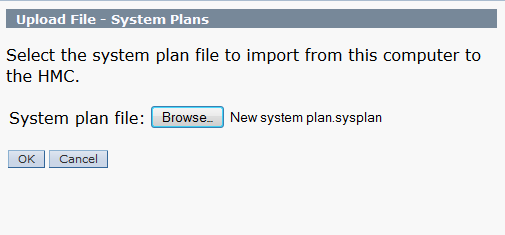
Figure 2-15 Confirm the deployment startup
The validation progress is displayed (Figure 2-16).

Figure 2-16 Validation of system plan deployment in progress
3. When validation completes (Figure 2-17), you can examine all the related messages. You can view the messages that are successful and the messages that are unsuccessful.

Figure 2-17 Example of successful validation
Figure 2-18 shows an example of a successful validation.

Figure 2-18 System plan deployment successful
4. On the Summary page, review the system deployment step order and click Finish. The HMC uses the system plan to create the specified logical partitions. This process can take several minutes.
Troubleshooting system plan deployment for an HMC
Use the following information to help resolve problems that you might encounter when deploying a system plan with the HMC Version 8, and later.
The system plan deployment process writes any messages, including error messages to the /var/hsc/log/iqzdtrac.trm file or to the /var/hsc/log/deploy_validation.log file if there are validation errors.
When you deploy a system plan, the validation process checks the information in the system plan with the configuration of the managed system. Some differences between the plan and the system can result in either hardware or partition validation errors. To deploy the system plan successfully, you must either change the system plan or change the target managed system.
2.5 System and partition templates
As the capabilities of PowerVM expand with the introduction of new technologies, the ability to provision virtual machines (VMs) quickly and efficiently becomes a key requirement.
The initial setup and configuration of Power Systems can be a complex process, and starting with the introduction of templates in IBM HMC V8.8.1.0.1, the provisioning of new Power Host systems and VMs has been simplified.
The Templates function allows the deployment of standard or customized templates for both systems and partitions.
Virtualization environment setup
A template is a collection of configuration preferences that can be quickly applied to multiple or single target IBM Power Systems. Templates can be used to set up your virtualization environment, and with preconfiguring of virtual resources, a highly customized template can be created to reduce the repetition of tasks when creating VMs.
Templates simplify the deployment process because templates contain many of the settings that previously were configured by using the HMC command-line interface (CLI) or the HMC graphical user interface (GUI) of previous versions. You can reuse a single template many times and modify templates to suit changes in environment requirements.
2.5.1 Template types
The two types of templates are as follows:
•System template
System templates are used to define system configuration settings that include general system properties and virtual environment settings.
•Partition template
Partition templates are used to define logical partition (LPAR) and VM settings, which include general partition properties, processor and memory configuration, virtual networks and virtual storage configuration, logical Host Ethernet Adapters (HEAs), and logical Single Root I/O Virtualization (SR-IOV) port settings.
The SR-IOV logical port settings allow virtualization of the physical ports of an adapter so that the ports can be shared by multiple partitions that are running simultaneously.
Templates do not contain target-specific information, so templates can be used to configure any system or partition in your environment. Partition templates can be used to deploy AIX, IBM i, and Linux logical partitions.
2.5.2 Predefined and custom templates
Templates can be further classified as predefined templates or custom templates.
Predefined templates contain configuration details for typical environment scenarios. Predefined templates are available for immediate use in the Templates and OS Images window. You cannot alter the predefined templates; however, you can copy and modify them for various needs.
Custom templates are templates that you create. Custom templates contain configuration details that are specific to your environment. You can create a custom template by using any of the following methods:
•Copy an existing template and modify the new template according to the requirements of your environment.
•Capture the configuration details of a currently running server or partition and save the details in to a new template.
2.5.3 Template overview
The deployment of logical partitions using the template function requires that you understand your physical infrastructure and how the infrastructure is virtualized. You also are required to ensure that the template can be used multiple times without changing it constantly.
Successful deployment of logical partitions from a template requires the careful planning, appropriate sizing, and configuration of your virtualization environment. The complexity of your environment might include some or all of the following components:
•Type of storage that is attached and how it is attached and presented to your environment. For example, allocated storage requires virtual SCSI or virtual fiber connections.
•Type of peripheral devices and how they are attached to your environment, For example, tape resources possibly require virtual fiber connections.
•Type of adapters that are installed in your Power Systems, for example, SR-IOV capable adapters.
•Type of Ethernet connectivity that is required and associated LAN or VLAN considerations.
•Type of VIOS implementation, for example, dual or single VIOS installations.
You need careful planning and configuring so that a template deployment of a system or partition can be an effective usage of the virtualized environment.
The successful deployment of templates requires simple steps, shown in Figure 2-19.

Figure 2-19 Template overview
2.5.4 Template workflow
Regardless of the template type, a system or partition template can be viewed, edited, copied, deleted, deployed, and exported. An understanding of the workflow for a template and how it can be customized to suit your environment allows the creation of templates that efficiently deploy systems or partitions from a template.
An understanding of this workflow shows how templates can be created and how they can be edited to enhance their effectiveness when creating systems or logical partitions from a template, as shown in Figure 2-20 on page 70.
The figure shows that a template that is deployed to a target system can be derived from a starter template or a custom template.
•For a starter template, the preferred practice is not to edit the original template to suit your environment, but to copy the starter template and edit the copied template to suit your current environment. You can use these practices to keep the original template in its original state if you want to create an additional template that is based on the starter template to incorporate a new or different infrastructure.
•A custom system template can be derived by capturing the configuration details of a system in a running state. This custom template includes information about the VIOS, virtual network, virtual storage, and system settings. You can capture and save these details as a custom system template by using the HMC.
A custom partition template can be derived by capturing the configuration details of a running partition or a partition that is not activated. Save the configuration details as a custom template to enable the creation of multiple partitions with the same configuration.

Figure 2-20 Template workflow
Figure 2-21 shows the functionality that is available with the templates in the Templates and OS Images window.

Figure 2-21 Template options in the Templates and OS Images window
These functions are incorporated in to the template workflow and provide the ability to use a template that can be quickly deployed. If changes are necessary, the template can be modified to suit your needs without re-creating the template.
Customized templates can be copied and modified to suit an individual application or infrastructure requirement. This flexibility is limited only by your requirements and needs.
2.5.5 Template contents
Because a template is effectively a collection of configuration details that are captured or configured, a system or a partition can be deployed from a template with minimal input.
The following sections of this chapter have more detail about the templates and their contents. Figure 2-22 shows a high-level diagram of the contents of a template; it also shows the relationships between the configuration details and the template.

Figure 2-22 Template contents
2.5.6 Accessing templates
To view configuration information by using the HMC, complete the following steps:
1. Choose one of the following navigation options depending on the HMC interface type:
– If you are using an HMC Enhanced interface, complete the following steps:
i. In the navigation area, expand Systems Management → Servers.
ii. Select a server and click Templates → Template Library.
– If you are using an HMC Enhanced+ interface, complete the following steps:
i. In the navigation pane, click the HMC Management icon. The icon represents the HMC Management function of the HMC.
2. In the Templates and O/S Images window, click the System tab.
3. Select the system template that you want to view and click Actions → View. You can view the details of Physical I/O, Host Ethernet Adapter, SR-IOV, Virtual I/O Servers, Virtual Networks, Virtual Storage, Shared Processor Pool, Shared Memory Pool and Reserved Storage, and Advanced System Settings by clicking the relevant tabs that are displayed. Alternately, you can view the template details from the Deploy System Template wizard.
4. Click Close.

Figure 2-23 Accessing the Templates function
|
Note: To use templates fully, you must understand both PowerVM Virtualization concepts and have experience with using the HMC.
For more information about PowerVM and its concepts, see the following publications:
•IBM PowerVM Virtualization Introduction and Configuration, SG24-7940
•IBM PowerVM Virtualization Managing and Monitoring, SG24-7590
•IBM PowerVM Enhancements What is New in 2013, SG24-8198
|
2.5.7 System templates
System templates contain configuration information about resources, such as system properties, shared processor pools, reserved storage pool, shared memory pool, physical I/O adapters, HEAs, SR-IOV adapters, VIOS, virtual networks, virtual storage, and initial program load (IPL).
Many of the system settings that are previously configured by using HMC V7.7.9.0 or earlier can now be completed by using a system template.
The Templates and OS Images includes predefined system templates that contain configuration settings that are based on common usage scenarios. Predefined system templates are available for your immediate use.
You can create custom system templates that contain configuration settings that are specific to your environment.
You can create a custom template by copying any template that is available in the Templates and OS Images and then changing the copy to suit your environment.
You can also capture the configuration of an existing system and save the details in a template. You can deploy that template to other managed systems that require the same configuration.
System templates are primarily used to deploy settings to new systems. To deploy new systems, complete the following tasks:
•View system template configuration information.
•Plan to deploy a system template.
•Capture a system configuration.
•Deploy a system by using a system template.
2.5.8 Viewing a system template
To view templates from HMC V8.8.4.0, complete the following steps:
1. Click HMC Management.

Figure 2-24 Templates and OS Images
3. Select a template, right-click it, and select View. A new window opens (Figure 2-25). In this window, you can select options on the left to use the various capabilities of PowerVM. These capabilities include Physical I/O, Virtual Storage, and Shared Processor Pools.

Figure 2-25 System template view
|
Note: To fully use the capabilities of system templates and to implement them in to managed systems, you must have a thorough understanding of PowerVM and its capabilities. For more information about this topic, see IBM PowerVM Virtualization Introduction and Configuration, SG24-7940.
|
Clicking Close at any menu option returns you to the Templates and OS Images window.
When you select certain menu choices shown in Figure 2-25 on page 74, the following windows open, which show the capabilities of a system template:

Figure 2-26 System View: Hardware Virtualized I/O

Figure 2-27 System View: Virtual Networks

Figure 2-28 Template View: Shared Memory Pool and Reserved Storage
2.5.9 Creating a system template
The two methods to create a system template from the HMC are as follows:
•Copy an existing template into a new template, which can then be modified as needed.
•Capture a running VIOS server or a VIOS server that is not in an activated state and save the configuration as a customized system template.
Copying a template
Complete the following steps:
1. From the Templates and OS Images window, select the system template to be copied, right-click the template, and select Copy, as shown in Figure 2-29.

Figure 2-29 System template: Copy
2. Enter an appropriate system template name, as shown in Figure 2-30.

Figure 2-30 System template: Copy name
3. Click OK.
After the copy completes, your new template is displayed in the Templates and OS Images, as shown in Figure 2-31.

Figure 2-31 Templates and OS Images: template is listed
Capturing a configuration as a template
You can capture the configuration details from a running VIOS or a VIOS that is in the not activated state and save the configuration as a custom system template.
The option to capture configuration as a template is available only when the managed system is in the running state.
This function is useful if you want to deploy multiple systems with the same configuration.
Complete the following steps:
1. From the HMC work pane, select the managed system containing the VIOS servers from which you want to create a template.
2. At the bottom of the work pane, expand Templates and then select Capture Configuration as Template, as shown in Figure 2-32 on page 79, to reveal the two available capture options:
– With Physical I/O
– Without Physical I/O
The configuration can be captured with or without physical I/O resources of the system. For managed systems with the same physical I/O resources, capturing with Physical I/O means that you do not have to select the resources on the target system manually upon template deployment.

Figure 2-32 Capture Configuration as Template menu
3. This example captures the configuration with physical I/O. When you are prompted for a template name and description, enter them, as shown in Figure 2-33.

Figure 2-33 Capture configuration: Name
4. Click OK to start the capture of the configuration.
After the configuration is captured, you are returned to the Templates and OS Images, as shown in Figure 2-34. The captured template is highlighted.

Figure 2-34 Templates and OS Images after capture
5. To look at the template properties, right-click the captured template and select View. Click Physical I/O to display the captured physical I/O resources, as shown in Figure 2-35. In a captured configuration with no physical I/O, no resources are displayed in this menu option.

Figure 2-35 System template with captured I/O
2.5.10 Editing a system template
To edit templates, in the Templates and OS Images window, right-click the selected template and select Actions → Edit, as shown in Figure 2-36.

Figure 2-36 System template: Edit
A new window opens (Figure 2-37). This is the initial system template edit window with the available menu options on the left side of the window.

Figure 2-37 Edit system template: initial window
To save any changes to your template from any menu option, click Save and Exit, which updates your template, as shown in Figure 2-37.
Clicking Save As saves your template configuration, including changes, in a new system template. This is the same process as copying a template, which is described in “Copying a template” on page 114.
You can click Virtual I/O Servers to modify a captured VIOS configuration and add an extra VIOS if your environment requires its implementation. Select the VIOS and right-click it to display the available options, as shown in Figure 2-38.

Figure 2-38 Edit system template: VIOS servers
Click View/Edit VIOS Details to edit the VIOS configuration. You can then edit the VIOS details, as shown in Figure 2-39.

Figure 2-39 Edit VIOS details: general
Clicking Show Advanced displays the available Advanced Settings for the VIOS. Modify these settings to suit your environment.
You can click the Processor tab to change the Processor mode, assign processor values, and change the Processor Compatibility Mode, as shown in Figure 2-40.

Figure 2-40 Edit VIOS details: processor
Click Show Advanced to display the option to change the Processor Compatibility Mode. Adjust the processor mode and processor values to suit your environment.
You can click the Memory tab to change the assigned memory, as shown in Figure 2-41. Adjust the memory requirements to suit your environment.

Figure 2-41 Edit VIOS details: memory
Click Save to update your VIOS configuration and return to Figure 2-38 on page 84.
Click Virtual Networks to modify the virtual networks that are on the managed system.
More virtual networks can be added to this system template. You can select the appropriate virtual network to modify the selected virtual network configuration, as shown in Figure 2-42.

Figure 2-42 Edit system template: Virtual Networks
Modify your virtual network settings to suit your environment.
You can click Virtual Storage to configure a Media Repository and specify a repository size, as shown in Figure 2-43.

Figure 2-43 Edit system template: Virtual Storage
Modify the virtual storage to suit your environment.
You can click Shared Processor Pool to modify the assigned reserved and maximum processing units.
Additional Shared Processor Pools with assigned reserved and maximum processing units can be added to the template, as shown in Figure 2-44.

Figure 2-44 Edit system template: Shared Processor Pool
Modify shared processor pools to suit your environment.
You can click Memory Pool and Reserved Storage to modify the configured Shared Memory Pool, as shown in Figure 2-45.

Figure 2-45 Edit System template: Shared Memory Pool
Modify the shared memory pool and reserved storage configurations to suit your environment.
|
Note: Not all menu choices are shown in this section. Depending on your environment, the other menu options might be relevant and require configuration to become part of your customized system template.
|
2.5.11 Deploying a template
The Deploy System from Template wizard guides you in providing target system-specific information that is required to complete the deployment on to the selected system. Before you deploy a system template, be sure the following prerequisites are met:
•The HMC is at version 8.8.4.0 or later.
•The hypervisor is in the operating or standby state.
•The managed system is in the operating or standby state.
•The managed system does not have any logical partitions that are associated to it.
If logical partitions are configured on the target system, an error message is displayed; if you continue with the deployment, the HMC completes the following actions:
– All system level configurations are initialized to the default values.
– All LPARs that are in the running state are shut down and removed automatically.
– All the Virtual I/O Servers that are in the running state are shut down and removed automatically.
The wizard completes the following tasks:
•Configures the system settings, assigns I/O adapters, and creates Virtual I/O Servers.
•Installs the VIOS software.
•Configures the network and storage I/O settings.
If you install the VIOS from a Network Installation Management (NIM) server, you must have the NIM server information that is required by the HMC.
When you deploy a system from a template, the HMC checks whether the configuration that is specified meets the required system capabilities.
To deploy a system template, select the target managed system in the HMC and select Templates → Deploy System from Template, as shown in Figure 2-46.

Figure 2-46 Deploy System from Template selection
Alternatively, select your system template from the Templates and OS Images, right-click the template, and select Action → Deploy, as shown in Figure 2-47.

Figure 2-47 Deploy: Templates and OS Images
The only difference between the two methods is that when you deploy from the Templates and OS Images window, you are prompted by the deployment wizard to select the target system.
Selecting Deploy on the system template starts the deployment wizard (Figure 2-48).

Figure 2-48 Deployment wizard
Click Next to move to the next tab.
You use the Select System tab to select the target system to which the template is deployed, as shown in Figure 2-49.

Figure 2-49 Deploy: Select a System
If you selected Deploy System from Template on the HMC work pane, the system is preselected in the Select System tab and you must select the system template that is used for the deployment.
When you select a target system, the Check option becomes available, as highlighted in Figure 2-49 on page 94.
|
Note: Click Check because the system must be reset to the manufacturer’s default configuration as part of the system template deployment wizard.
|
The target system also is checked for available logical partitions, which are removed, as with the tasks that are involved with deploying a system from a system template. The target system that is selected for the deployment that is detailed in this section has no partitions that are configured (Figure 2-50) and had the Check option selected.

Figure 2-50 Deploy: Check target system
Close this window and click Next to move to the next tab.
The deployment wizard checks the target system for available resources.
As shown in Figure 2-51, the SR-IOV Adapter Settings tab is skipped because the selected system has no SR-IOV capable adapters. The VIOS Configuration Summary tab shows the VIOS configuration that is specified by the system template. To review the template, click Template Details.

Figure 2-51 Deploy: VIOS Configuration Summary
The template can be viewed only when you click Template Details, as described in 2.5.8, “Viewing a system template” on page 74.
If you want to edit the template details, cancel the deployment wizard, edit the system template, and then recommence with the deployment wizard.
The system template in this example has only one VIOS specified; a template with an additional VIOS displays the second VIOS server in this tab.
Click Next to move to the next tab.
You use the Physical I/O tab to select the physical resources on the target system that will be allocated to the VIOS. Expanding Physical I/O Adapters displays the available physical resources on the target system, as shown in Figure 2-52.

Figure 2-52 Deploy: Physical I/O
Select the resources to suit your environment by selecting the radio button next to the required resource.
Expanding Host Ethernet Adapters displays the HEA resources that are available on the target system.
As shown in Figure 2-53, an HEA port can be either a Dedicated or Shared resource. Select the drop-down box next to the required port and assign the port to the VIOS. If the VIOS will share a HEA port, set the required port as a Shared resource and select the check box next to the HEA that you want to assign to the VIOS.

Figure 2-53 Deploy: Physical I/O - HEA
HEAs and SR-IOV Logical Ports display resources only if they are supported by your target system.
Select the resources to suit your environment and click Next to move to the next tab.
You use the System Configuration Progress tab to apply system settings to the target system and create the VIOS partition. Click Start to begin this process (Figure 2-54).

Figure 2-54 Deploy: System Configuration Progress
If you do not click Start but click Next instead, an error prompt opens in the deployment wizard window (Figure 2-55).

Figure 2-55 Deploy: System Configuration Progress - error
Click Start to apply the system settings and to create the VIOS partition.
The template deployment wizard applies the system configuration and creates the VIOS partition on the target system.
The deployment shows the successful creation of a VIOS partition on the target system (Figure 2-56).

Figure 2-56 Deploy: System Configuration Progress - success
Click Next to move to the next tab.
You use the VIOS Installation Configuration tab to select the installation method for VIOS. If you use a NIM server for installation, you need the appropriate authentication credentials.
For each VIOS server, specify the Ethernet port and TCP/IP configuration, as shown in Figure 2-57.

Figure 2-57 Deploy: VIOS Installation Configuration
Select the resources and TCP/IP configuration to suit your environment.
Click Next to move to the next tab.
You use the VIOS Installation Progress tab to establish a Resource Monitoring and Control (RMC) connection between the HMC and VIOS logical partition.
Click Start to establish the RMC connection, as shown in Figure 2-58.

Figure 2-58 Deploy: VIOS Installation Progress
After the RMC connection is established, click Next to move to the next tab.
You use the Network Bridge Configuration tab to set up network bridges, as shown in Figure 2-59.

Figure 2-59 Deploy: Network bridge configuration
Select the resources to suit your environment and click Next to move to the next tab.
You use the Storage Configuration tab to create and configure a Shared Storage Pool if one is required by your environment.
A Reserved Storage Device Pool can be configured, as shown in Figure 2-60.
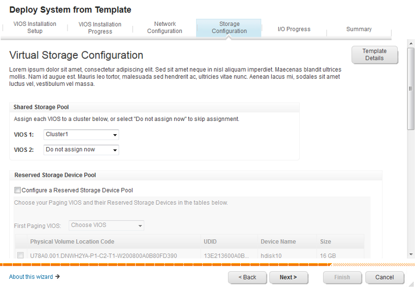
Figure 2-60 Deploy: Reserved Storage Device configuration
Configure the virtual storage to suit your environment and click Next to move to the next tab.
The I/O Progress tab shows the progress of the VIOS configuration on the target system after you click Start, as shown in Figure 2-61. The deployment wizard displays the progress of the VIOS installation and the configuration of virtual storage, as specified in the Storage Configuration tab of the wizard.

Figure 2-61 Deploy: I/O Progress tab
The deployment wizard shows the successful creation of a VIOS running on the target system.
Click Next to move to the Summary tab, which shows the results of the wizard (Figure 2-62).

Figure 2-62 Deploy: Summary
At this stage, the target system has a running VIOS with your configuration and is ready to accept VIOS client logical partition connections, which can be created by using partition templates (for more information, see 2.6, “Partition templates” on page 108).
2.5.12 Exporting a system template
The new template functions of the HMC can export your system template configuration. To do so, select your template in the Templates and OS Images, right-click your system template, and select Export. A dialog box opens, as shown in Figure 2-63.

Figure 2-63 Export of system template
You can use this function to export your template configuration to another HMC that supports templates. To do so, click Export in the Templates and OS Images.
You also can use this function as an off-site type backup of your customized templates.
2.5.13 Deleting a system template
The template functions of the HMC can delete your template configuration. To do so, select your system template in the Templates and OS Images, right-click your template, and select Delete. A dialog box opens, as shown in Figure 2-64.

Figure 2-64 Delete a system template
2.6 Partition templates
With HMC V8.8.4.0, you can create an AIX, IBM i, or Linux logical partition from any predefined or custom template in the Templates and OS Images.
The managed system must be in a running state before you can create a logical partition from a template on that managed system. You cannot create a partition from a template when the server is in a powered off state.
|
Notes:
•You can choose to work with one template at a time, whether you are editing, viewing, or deploying a template.
•You can select only one system at a time when deploying a partition template.
|
2.6.1 Viewing templates
To view templates from the HMC, select your managed system from the navigator pane and, at the bottom of the work pane, expand Templates, as shown in Figure 2-65.
Figure 2-65 Template menu
Complete the following steps:
1. Click Templates and OS Images. A new window opens, where you can view the available templates. Click the Partition tab, as shown in Figure 2-66.

Figure 2-66 View the template
2. Right-click the template that you want to view and see the available options for the template.
3. Click View to display the initial template window, where you can navigate to the required option and view its properties (Figure 2-67). When you finish with this view, click Close.

Figure 2-67 View template: Properties - Name
Click the General tab and then click Show Advanced to open the window that displays the advanced properties of the template (Figure 2-68).

Figure 2-68 View template: Properties - General tab
|
Notes:
•When you deploy the template to create a logical partition profile, the template’s assigned values are imported into the profile.
•To see the advanced options for each tab, click Show Advanced, and each tab displays its advanced options when it is opened.
|
Click the Processor tab to show the processor configuration that is specified by this template.
As shown in Figure 2-69, this template is configured for Dedicated mode with assigned values and a default Processor Compatibility Mode. If you want to change the Processor mode to, for example, Shared Mode, you must edit the template, which is described in 2.6.3, “Editing templates” on page 116.

Figure 2-69 View template: Properties - Processors tab
Click the Memory tab to show the memory configuration that is specified by this template, which is shown in Figure 2-70.

Figure 2-70 View template: Properties - Memory tab
If you click Virtual Networks in the Template View window, you can see whether the template is configured for either of the following mode options, which are shown in Figure 2-71:
•Choose Virtual Networks during Deployment
•Specify Virtual Networks in this Partition Template

Figure 2-71 View template: Virtual Networks
If you click Virtual Storage in the Template View window, you see the following extra tabs:
•Virtual SCSI
•Virtual Fibre Channel
•Virtual Optical Device
For each tab, you can view how each virtual resource type is configured, with these options:
•Configure virtual resource during deployment
•Configure virtual resource with captured information
•Do not configure virtual resource
For this example (Figure 2-72), the Virtual SCSI is configured to Configure the Virtual SCSI storage during deployment.

Figure 2-72 View template: Virtual Storage
If you click Hardware Virtualized I/O and then the appropriate tab, you see the options that are selected for SR-IOV or HEA resources, as shown in Figure 2-73.

Figure 2-73 View template: Hardware Virtualized I/O
2.6.2 Creating templates
The two methods to create a partition template through the HMC are as follows:
•Copy an existing template in to a new template, which can then be modified as needed.
•Capture a running logical partition or a logical partition that is not in an activated state and save the configuration as a customized template.
Copying a template
From Templates and OS Images, click the System tab, right-click the template that you want to copy, and click Copy. For this example, we copy one of the starter templates, as shown in Figure 2-74.

Figure 2-74 Copy of a template
Enter an appropriate template name and click OK.
After the copy completes, your new template is listed in the Templates and OS Images, as shown in Figure 2-75.

Figure 2-75 Copied template
Capturing a logical partition to create a template
You can capture the configuration details from a running partition or a partition that is in the not activated state and save the configuration as a custom template.
This function is useful if you want to create multiple partitions with the same configuration from a correctly configured logical partition, including virtual resources that are used in your environment.
In the HMC, click the Resource icon, select All Partitions, select the logical partition from which you want to create a template. Click Actions → Templates → Capture Partition as Template, as shown in Figure 2-76.

Figure 2-76 Capture Configuration as Template
A window opens. You are prompted to name your captured template and provide an optional description of it, as shown in Figure 2-77.

Figure 2-77 Naming the captured logical partition
Click OK to begin the capture.
After the capture function completes, the Templates and OS Images window opens, where you can view your captured template, as shown in Figure 2-78.

Figure 2-78 Captured logical partition as a template
A template that is created by copying an existing template or by capturing a configured logical partition can be edited or recopied. These edited or recopied templates create additional templates that can, for example, be used for specific applications requirements by making granular changes from a base template.
2.6.3 Editing templates
To edit templates, on the HMC, select your managed system in the navigator pane, and in the work pane, expand Templates.
Select Templates and OS Images from the menu choices to view the available templates, which display in a new window. Click the Partition tab and the template you want to edit.
Right-click the template and select Edit, as shown in Figure 2-79. In this example, the AIX Capture template is selected to edit the template properties.

Figure 2-79 Edit a partition template
A window opens, as shown in Figure 2-80. You can change the name of your template by modifying the Template Name and then clicking Save and Exit.

Figure 2-80 Edit template: Name/Description tab
While you are using the template edit function, within any menu or tab, clicking Save and Exit saves the edited changes and reopens the Templates and OS Images window.
Clicking Save As initiates the template copy function, which is described in “Copying a template” on page 114.
Click Properties and then the General tab (Figure 2-81). Click Show Advanced to display the advanced parameters.

Figure 2-81 Edit template: General tab
Because you selected the Show Advanced option, all tabs of the Properties menu show the advanced properties for each tab by default.
In this example, the following properties are specified:
•Maximum number of Virtual Adapters
•Enabled Connection Monitoring
•Enabled Performance Information Collection
Modify your selections to suit your environment.
You can click the Processor tab to change the Processor mode, assign processor values, and change the Processor Compatibility Mode. To change the processor mode from Dedicated to Shared, click the Processor Mode drop-down box, as shown in Figure 2-82.

Figure 2-82 Edit template: Processor tab
In this example, changing the Processor Mode to Shared enables the editing of the Virtual Processors and Processing Units. A value can be set by either entering the required value or moving the slider arm to the wanted value.
You can use Processor Compatibility Mode to select the appropriate mode, with selections from POWER6 to POWER8-enhanced. For more information about Processor Compatibility Modes, see 1.2.12, “POWER8 processor-based systems support” on page 25.
Modify the processor assigned values to suit your environment.
You can click the Memory tab to change the Memory Mode. To change the Memory Mode from Dedicated to Shared, click the Memory Mode drop-box, as shown in Figure 2-83.

Figure 2-83 Edit template: Memory tab
In this example, the Memory Mode remains as dedicated memory and has the assigned values that are shown.
Under this tab is the PowerVM capability of Active Memory Expansion (AME). Select the check box and enter an appropriate AME factor.
Selecting Shared Memory Mode changes the Advanced Settings in the memory tab, as shown in Figure 2-84.

Figure 2-84 Edit template: Shared memory advanced settings
Modify the memory configuration to suit your environment.
You can click Virtual Networks so that the template can choose either of the following settings:
•Choose Virtual Networks during Deployment
•Specify Virtual Networks in this Partition Template
Figure 2-85 shows that this template specifies a virtual network during deployment and has an appropriate value.

Figure 2-85 Edit template: Virtual Networks
if you are using the template function to create a logical partition and specify virtual resources in the template, the preferred practice is that the virtual resources are created before editing the template.
If no virtual networks are specified on the managed system and you select the Choose Virtual Networks during Deployment option, no available options display during template deployment. This situation is covered in more detail in 2.6.4, “Deploying templates” on page 125.
Modify the virtual network configuration to suit your environment.
You can also view the properties of a virtual Network Interface Controller (vNIC) in a partition profile by using the HMC, as shown in Figure 2-86.

Figure 2-86 Edit template virtual NICs
A virtual Network Interface Controller (vNIC) is a type of virtual Ethernet adapter that can be configured on client logical partitions. Each vNIC is backed by a single root I/O virtualization (SR-IOV) logical port that is owned by the VIOS.
You can click Virtual Storage so that the template can be configured with the following PowerVM capabilities:
•Virtual SCSI
•Virtual Fibre Channel
•Virtual Optical Device
As shown in Figure 2-87, the new template can include virtual storage resources as part of your template deployment.

Figure 2-87 Edit template: Virtual Storage
Depending on the environment that is used by the logical partition that you are going to deploy from this template, you can create virtual SCSI adapters, virtual Fibre Channel adapters, and virtual optical devices.
In this example, during the template deployment, you are prompted to configure your virtual resources as you create the logical partition. To use the template to deploy virtual resources, have a thorough understanding of PowerVM and its concepts.
Modify the virtual storage to suit your environment.
When you click Save and Exit at any time while using the template edit function, the HMC saves the changes and returns to the Templates and OS Images window.
As shown in Figure 2-88, the edited changes are saved, and the template details in the Templates and OS Images window are changed.

Figure 2-88 Edited template
For the AIX Capture template shown in Figure 2-88, the Processor mode was changed from Dedicated to Shared Mode and the virtual networks were updated to include details about the configured virtual networks.
2.6.4 Deploying templates
To create a logical partition by deploying it from a template, complete the following steps:
1. click HMC Management, click Templates and OS Images, select your template, right-click the template, and select Deploy, as shown in Figure 2-89.

Figure 2-89 Template deployment from the Templates and OS Images
If you selected Create Partition from Template, the only difference from the window that is shown in Figure 2-90 is an additional tab where you must specify the template to use for the deployment.

Figure 2-90 Initial deployment wizard window
2. Click Next to move to the next tab.
3. In the Select System tab, select the managed system that you want to deploy with the selected template. For this example, SystemB is selected, as shown in Figure 2-91.

Figure 2-91 Deployment: system
4. Click Next to move to the next tab.
In the Partition Configuration tab, enter the name of your logical partition, which at the completion of the wizard displays under the selected managed system in the work pane, as shown in Figure 2-92.

Figure 2-92 Deployment: Partition Configuration
This tab also displays the type of logical partition to be created and the Processor and Memory configurations that are specified by the template. In this case, the template deploys an IBM i logical partition with 0.2 shared processors and 2.5 GB of memory.
To verify the template configuration, click Template Details in the wizard window to view the template configuration, which displays the template details, but you cannot edit the template. If your template details must be edited, cancel the deployment wizard and edit your template, save the changes, and then restart the deployment wizard.
5. Click Next to move to the next tab.
The Physical I/O tab has three available options.
– Physical I/O: Assign physical I/O to the logical partition.
– Logical Host Ethernet Adapter: Assign a logical port on a HEA.
– Logical SR-IOV Ethernet Adapters: Assign a logical port on an SR-IOV Ethernet Adapter.
Depending on your environment, expand the appropriate option and, as Figure 2-93 shows, select the required physical I/O resource that will be assigned to the partition as part of the logical partition deployment.

Figure 2-93 Deployment: Physical I/O
If your managed system does not have HEA or SR-IOV resources, expanding the options does not display any options. For the managed system that is selected in this example, an HEA resource exists, but no SR-IOV resource, as shown in Figure 2-94.

Figure 2-94 Deployment: Physical I/O additional
Modify the assigned resources to suit your environment.
6. Click Next to move to the next tab.
In the Network Configuration tab, you see the virtual network that is specified by the template which is used for the logical partition deployment.
Figure 2-95 shows that the template was specified to use a virtual network, named DMZ, by using the Specify Virtual Networks in this Partition Template item of the Virtual Networks menu of the template and completing the appropriate values.

Figure 2-95 Deployment: Network Configuration
If the template is specified with the Choose Virtual Networks during Deployment option, the wizard displays the available virtual networks on the managed system.
The wizard displays the available networks and selections for the logical partition requirements (Figure 2-96).

Figure 2-96 Deployment: Virtual Network
7. Click Next to move to the next tab.
The Storage Configuration tab (Figure 2-97) has three options that are available for your virtual storage:
– Virtual SCSI
– Virtual Fibre Channel
– Virtual Optical Device

Figure 2-97 Deployment: Virtual Storage initial
You can expand Virtual SCSI to assign physical volumes to your logical partition. Figure 2-98 shows volumes that are present and can be selected. Entering a volume name allows for multiple deployments to determine what volumes already are selected and to which logical partition they are assigned.

Figure 2-98 Deployment: Storage - Virtual SCSI
Selecting multiple volumes is supported, as shown in Figure 2-99.

Figure 2-99 Deployment: Storage - Multiple Volumes
8. Click Edit Connections in the wizard window.
9. The Edit Connections window opens (Figure 2-100). Use it to modify the virtual SCSI connections to the physical volumes that are specified, as shown in the figure.

Figure 2-100 Deployment: Virtual SCSI connections - Multiple
If your managed system has multiple Virtual I/O Servers, you can select which VIOS you want for your virtual SCSI connections:
– Figure 2-99 on page 133 shows that multiple volumes were selected to be assigned to the logical partition upon deployment.
– Figure 2-100 shows that each volume has its own virtual SCSI connection, which might not be the configuration you want.
10. To associate multiple volumes with a single virtual SCSI connection, select only one volume at the time of deployment, as shown in Figure 2-101. After the logical partition is created, use the logical partition management functions to add the additional volumes to the created virtual SCSI connector.

Figure 2-101 Deployment: Virtual SCSI Connections - Single
11. Expand Virtual Fibre Channel to view the available Fibre Channel adapters per VIOS, as shown in Figure 2-102.

Figure 2-102 Deployment: Virtual Fibre Channel
12. You can select a Fibre Channel adapter and click Edit Connections to enter appropriate WWPN values manually. If the fields are blank (Figure 2-103), the managed system auto-generates the WWPN values.

Figure 2-103 Virtual Fibre Channel connections
Expanding Virtual Optical Drive shows the available virtual optical devices, if they are present in your managed system. If they are present, create a connection to the virtual optical device.
13. Modify the virtual storage connections to suit your environment, and then click Next to move to the next tab.
14. For an IBM i logical partition, as part of the deployment, the Tagged I/O Device Configuration must be specified.
While you are using the deployment wizard, if you specified virtual storage connections, you can use the drop-down menu to select Virtual SCSI Slot for the Load Source and Alternate Restart Devices fields, as shown in Figure 2-104.

Figure 2-104 IBM i Tagged I/O Device Configuration
15. Modify the Tagged I/O to suit your environment, and then click Next to move to the next tab.
The Summary tab (Figure 2-105) displays your selections and is the final opportunity if you want to go back and modify your settings before you start the deployment of the logical partition from the template. You can click Back to go back to the previous tabs and modify the setting in those tabs.

Figure 2-105 Deployment Summary tab
Use the remaining option, highlighted in the figure on this Summary tab to decide whether to activate the partition after deployment or to create the logical partition only after deployment.
If your logical partition has multiple volumes and you have not specified them as part of the template deployment wizard, create the partition and then modify the logical partition configuration by using the PowerVM Management functions.
16. Click Finish when you are ready to begin the deployment of your logical partition on to your managed system.
17. With a properly configured template and PowerVM environment, a successful deployment of your template can be achieved, as shown in Figure 2-106. Click Close.

Figure 2-106 Deployment completed successfully
Select your managed system from the navigator pane of the HMC to now show the created logical partition that is based on the template configuration, as shown in Figure 2-107.

Figure 2-107 Logical partition created in a managed system
2.6.5 Exporting templates
Included with the new template functions of HMC is the ability to export your partition template configuration.
To export your template, select your template in the Templates and OS Images, right-click your template, and select Export. The window that is shown in Figure 2-108 opens.
Figure 2-108 Export of a partition template
This function can be used to export your template configuration to another HMC that supports templates. To import the template, click Import in the Templates and OS Images in the other HMC.
This function also can be used as an off site type backup of your customized templates.
2.6.6 Deleting templates
Included with the new template functions of HMC V8.8.4.0 is the ability to delete your template configurations. To do so, select your template in the Templates and OS Images, right-click your template, and select Delete. The window that is shown in Figure 2-109 opens. To delete the template, click Yes.

Figure 2-109 Delete Template
2.7 Virtualization introduction
This section describes basic concepts of PowerVM and Virtualization in a Power Server environment.
2.7.1 PowerVM introduction
IBM PowerVM provides the industrial strength virtualization solution for IBM Power Systems servers. Based on more than a decade of evolution and innovation, PowerVM represents the state of the art in enterprise virtualization and is broadly deployed in production environments worldwide by most Power systems owners. The IBM Power systems family of servers includes proven workload consolidation platforms that help clients control costs while they improve overall performance, availability, and energy efficiency.
PowerVM can help eliminate under utilized servers because it is designed to pool resources and optimize their use across multiple application environments and operating systems. Through advanced virtual machine (VM) capabilities, a single VM can act as a separate IBM AIX, IBM i, or Linux operating environment, by using dedicated or shared system resources.
For more information about PowerVM, see IBM PowerVM Virtualization Introduction and Configuration, SG24-7940 and IBM PowerVM Virtualization Managing and Monitoring, SG24-7590.
Processor virtualization
PowerVM can automatically adjust pooled processor resources across multiple operating systems, borrowing capacity from idle VMs to handle high resource demands from other workloads.
Micro-Partitioning
IBM Micro-Partitioning supports multiple VMs per processor core and, depending upon the Power Systems model, can run up to 1000 VMs on a single server, each with its own processor resources.
Multiple Shared Processor Pools
Multiple Shared Processor Pools allow for the automatic nondisruptive balancing of processing power between VMs assigned to shared pools, resulting in increased throughput.
Shared Dedicated Capacity
Shared Dedicated Capacity allows for the “donation” of spared CPU cycle from dedicated processor VMs to a Shared Processor Pool. Because a dedicated VM maintains absolute priority for processor cycles, enabling this feature can increase system utilization without compromising the computing power for critical workloads.
Power Enterprise Pool
A Power Enterprise Pool is a group of enterprise systems that can share Mobile Capacity on Demand (CoD) processor and memory resources. With this you can flexible manage large workloads in a pool of systems and rebalance the resources to respond to business need.
For more information about Power Enterprise Pools, see Power Enterprise Pools on IBM Power Systems, REDP-5101.
Memory virtualization
With PowerVM, pooled memory resources can be adjusted across multiple operating systems, to handle high resource demands from other workloads.
Active Memory Sharing
IBM Active Memory Sharing (AMS) is a technology that can intelligently and dynamically reallocate memory from one VM to another for increased utilization, flexibility, and performance. AMS enables the sharing of a pool of physical memory among VMs on a server, helping to increase memory utilization and lower system costs. The memory is dynamically allocated among the VMs as needed to optimize the overall physical memory usage in the pool.
For more information about Active Memory Sharing, see IBM PowerVM Virtualization Active Memory Sharing, REDP-4470.
Active Memory Deduplication
Active Memory Deduplication is a powerful optimization feature that can be enabled when Active Memory Sharing is in use. This memory optimization intelligently detects and removes duplicate memory pages that are used between VMs and as a result reduces overall memory consumption.
I/O virtualization
PowerVM can automatically adjust pooled processor resources across multiple operating systems, borrowing capacity from idle VMs to handle high resource demands from other workloads.
Virtual I/O Server (VIOS)
The VIOS is a special purpose VM that can be used to virtualize I/O resources for AIX, IBM i, and Linux client VMs. The VIOS owns the resources that are shared with clients. A physical adapter that is assigned to the VIOS can be shared by one or more other VMs. The VIOS can reduce costs by eliminating the need for dedicated network adapters, disk adapter and disk drives, CD-ROMS, and tape adapters and tape drives in each client VM. With VIOS, client VMs can easily be created for test, development, or production purposes.
Shared Storage Pools
Shared Storage Pools (SSP) allows storage subsystems to be combined into a common pool of virtualized storage that can be shared by the Virtual I/O Server on multiple Power Systems. SSP supports capabilities such as thin provisioning, whereby VM storage is dynamically allocated and released as required, to improve overall storage resource utilization.
Virtual Fibre Channel
Virtual Fibre Channel, or N_Port ID Virtualization (NPIV), provides direct access to Fibre Channel adapters from multiple VMs, simplifying the deployment and management of Fibre Channel SAN environments.
Single root I/O virtualizaton (SR-IOV)
Single root I/O virtualization (SR-IOV) is a peripheral component interconnect express (PCIe) standard architecture that define extensions to PCIe specifications to enable multiple logical partitions running simultaneously within a system to share PCIe devices. The architecture defines virtual replicas of PCI functions known as virtual functions (VF). A logical partition can connect directly to an SR-IOV adapter VF without going though a virtual intermediary (VI) such as a Power Hypervisor or Virtual I/O Server. This provides for a low latency and lower CPU utilization alternative by avoiding a virtual intermediary.
Server virtualization
Server virtualization allows for the following key functions.
Live Partition Mobility (LPM)
LPM supports the movement of a running AIX, IBM i, or Linux VM from one Power Systems server to another without application downtime. This component helps to avoid application interruption for planned system maintenance, provisioning, and workload management. LPM can be used to simplify migration of operating environments to new servers temporarily or permanently.
Partition Suspend and Resume
The state of a partition can be suspended and resumed at a later time. The applicability and benefits of the suspend/resume feature include resource balancing and planned system outages for maintenance or upgrades. Lower priority or long running workloads can be suspended to free resources.
Partition Remote Restart
A logical partiton can be remotely restarted. Use this feature to recover the partitions quickly during a source server failure.
Partition simplified Remote Restart
The partition state and configuration data of a logical partition is automatically stored on each managing HMC. Any change to the partition configuration or profile is automatically synchronized with the data that is stored on the HMC.
Further virtualization features
Additional virtualization features are described in the following sections.
Active Memory Mirroring for Hypervisor
With active Memory Mirroring for Hypervisor, two identical copies of the system hypervisor of a managed system are maintained in memory always. But copies are simultaneously updated with any changes. If a memory failure occurs on the primary copy, the second copy is automatically called, eliminating platform outages due to uncorrectable errors in system hypervisor memory. Active Memory Mirroring for hypervisor is designed to ensure that system operations continues even in the unlikely event of an uncorrectable error that is occurring in main memory that is used by the system hypervisor.
Coherent Accelerator Processor Interface (CAPI)
With CAPI, an I/O adapter can be used as a coherent accelerator to participate in a memory coherency domain to accelerate system workloads.
Dynamic Platform Optimization
With Dynamic Platform Optimizer, you can dynamically optimize the placement of partitions. This function increases the processor-memory affinity of the partitions to improve the performance.
IBM i 5250 Application
With IBM i 5250 Application, you can run 5250 applications on the IBM i partitions of the managed system. The 5250 applications include all 5250 sessions (such as 5250 emulation, Telnet, and screen scrapers), interactive system monitors, and twin axial printer jobs.
2.7.2 Virtualization by using an HMC
With the HMC, you can control the virtualization of Power Systems servers (also called managed systems). The HMC uses a web-bossier-based interface or a command-line interface (CLI) to create and manage logical partitions (LPARs).
Logical partitions are a virtualized subset of the hardware resources of a physical system. An IBM Power System server can be partitioned into multiple logical partitions. Each logical partition can have a separate operating system: AIX, IBM i, or Linux.
Processor virtualization
The virtualization of physical processors in IBM Power Systems introduces an abstraction layer that is implemented within the IBM POWER® Hypervisor. The Power Hypervisor abstracts the physical processors and presents a set of virtual processors to the operating system within the micro-partitions on the system. A micro-partition can have a minimum of 0.05 (0.1 with POWER7 technology-based servers) of a processor up to the total processor capacity in the system. The granularity of processor entitlement is 0.01 of a processor, allowing entitlement to be precisely determined and configured.
In contrast, dedicated-processor logical partitions can be only allocated whole processors, so the maximum number of dedicated-processor logical partition in a system is equal to the number of physical activated processors.
Memory virtualization
IBM Power Systems provide dedicated memory allocation, and with two features (Active Memory Sharing and Active Memory Expansion) for memory virtualization, you can increase the flexibility and overall usage of physical memory:
•Dedicated
The physical memory is distributed among the partitions.
•Active Memory Sharing (AMS)
AMS enables the sharing of a pool of physical memory among AIX, IBM i and Linux partitions. The memory is dynamically allocated among the partitions as needed to optimize the overall physical memory usage in the pool.
•Active Memory Expansion (AME)
AME is the ability to expand the memory that is available to an AIX partition beyond the amount of assigned physical memory. AME compresses memory pages to provide more memory capacity for a partition. Since the POWER7+ processor, a hardware accelerator is embedded in the processor chip for AIX memory compression. This offloads compression work from the processor and improves the overall performance.
Virtual I/O
Virtual I/O describes the ability to share physical I/O resources between partitions in the form of virtual adapters that are in the managed system.
Power Hypervisor for virtual I/O
The Power Hypervisor (PHYP) provides the interconnection for the partitions. To use the function of virtual I/O, a partition uses a virtual adapter as shown in Figure 2-110. The PHYP provides the partition with a view of an adapter that has the appearance of an I/O adapter, which might or might not correspond to a physical I/O adapter.

Figure 2-110 Role of PHYP for virtual I/O
Virtual I/O Server (VIOS)
The VIOS can link the physical resources to the virtual resources. By this linking, it provides virtual storage and Shared Ethernet Adapter capability to client logical partitions on the system. It allows physical adapters with attached disks on the VIOS to be shared by one or more client partitions.
VIOS mainly provides the following functions:
•Serves virtual SCSI devices to clients.
•Serves virtual Fibre Channel devices to clients.
•Provides Shared Ethernet Adapters for virtual Ethernet.
The VIOS is installed in its own logical partition. The VIOS partition is a special type of partition that is marked as such in the Create Logical Partitioning Wizard.
For further information about VIOS, see IBM PowerVM Virtualization Introduction and Configuration, SG24-7940.
Virtual Small Computer System Interface (virtual SCSI)
Virtual SCSI is based on a client/server relationship. A VIOS partition owns the physical resources and logical client partitions access the virtual SCSI resources that are provided by the VIOS partition. The VIOS partition has physically attached I/O devices and exports one or more of these devices to other partitions, as shown in Figure 2-111.

Figure 2-111 Virtual SCSI overview
Figure 2-111 shows that the virtual SCSI adapters on the server and the client are connected through the Hypervisor. The virtual SCSI adapter drives (server and client) communicate control data through the Hypervisor.
When data is transferred from the backing storage to the client partition, it is transferred to and from the clients data buffer by the DMA controller on the physical adapter by using redirected SCSI Remote Direct Memory Access (RDMA) Protocol. This facility enables the VIOS to securely target memory pages on the client to support virtual SCSI.
Virtual Fibre Channel
Just as with the virtual SCSI adapters, virtual Fibre Channel adapters (N_Port ID Virtualization (NPIV)), are based on a client/server relationship (Figure 2-112) and communicates control data through the Hypervisor.
On Power System server, Virtual Fibre Channel allows logical partitions to have dedicated N_Port IDs (WWN), giving the operating system a unique identity to the SAN. Virtual Fibre Channel is supported by AIX, IBM i, and Linux partitions.

Figure 2-112 NPIV overview
Virtual Ethernet
Virtual Ethernet enables inter-partition communication without having physical network adapters that are assigned to each partition. Virtual Ethernet is a convenient and cost-saving option to enable partitions within a single system to communicate with one another through a virtual Ethernet LAN. These connections exhibit characteristics that are similar to physical high-bandwidth Ethernet connections and support multiple protocols (IPv4, IPv6, and Internet Control Message Protocol (ICMP)).
Virtual LAN (VLAN)
VLAN is a technology that is used for establishing virtual network segments on top of physical switch devices. Multiple VLAN logical devices can be configured on a single system, as shown in Figure 2-113. Each VLAN logical device constitutes an extra Ethernet adapter instance. These logical devices can be used to configure the same types of Ethernet IP interfaces as are used with physical Ethernet adapters.

Figure 2-113 VLAN example of two VLANs
Virtual Ethernet connection
Virtual Ethernet connections use VLAN technology to ensure that partitions can access only data that is directed to them. The Power Hypervisor provides a virtual Ethernet switch function that is based on the IEEE 802.1Q VLAN standard that enables partition communication within the same servers, as shown in Figure 2-114. The connections are based on an implementation internal to the Hypervisor that moves data between partitions.

Figure 2-114 Virtual Ethernet connection
Shared Ethernet Adapter (SEA)
An SEA bridges external networks to internal networks. The SEA hosted in the VIOS partition acts as an OSI Layer 2 switch between the internal and external network.
Figure 2-115 shows the Shared Ethernet Adapter in a Virtual I/O Server that is used as a bridge between the virtual and physical Ethernet.

Figure 2-115 Shared Ethernet Adapter configuration
The bridge is transparent to the Internet Protocol (IP) layer. For example, when an IP host sends an IP datagram to another host on a network that is connected by a bridge, it sends the datagram directly to the host. The datagram crosses the bridge without the sending IP host being aware of it.
Live Partition Mobility (LPM)
With LPM, AIX, IBM i, and Linux partitions can be moved from one system to another. The mobility process transfers the system environment that includes the processor state, memory, attached virtual devices, and connected users.
You can use the HMC to move an active or inactive logical partition from one server to another:
•Active partition mobility moves AIX, IBM i, or Linux logical partitions while they are running, including the operating system and applications, from one system to another. The logical partition and the applications that run on that migrated partition do not need to be shut down.
•Inactive partition mobility moves a powered-off AIX, IBM i, or Linux logical partition from one system to another.
Because the HMC always moves the last activated profile, an inactive logical partition that has never been activated cannot be moved. For inactive partition mobility, you can either select the partition that is defined in the Hypervisor, or select the configuration data that is defined in the last activated profile on the source server.
Host Ethernet Adapter (HEA)
HEA is a physical Ethernet adapter that is integrated directly into the system bus on a managed system. HEAs offer high throughput, low latency, and virtualization support for Ethernet connections. HEAs are also known as Integrated Virtual Ethernet adapters (IVE adapters). Multiple logical partitions can connect directly to the HEA and use the HEA resources, This configuration allows these logical partitions to access external networks through the HEA without having to go through an Ethernet bridge (for example Shared Ethernet Adapter) or another logical partition (for example “Virtual I/O Server”).
2.8 Reliability, availability, and serviceability (RAS) on the HMC
The HMC is used for configuration, management, and maintenance of Power Systems. The HMC is considered to be part of the server firmware, so it is one of the resources that contributes to the system stability and normal operation.
2.8.1 Dual HMC and redundancy
You can configure a redundant HMC in a configuration in which dual HMC servers are connected to the service processors.
Using a redundant HMC configuration with your service processor setup requires a specific port configuration, as shown in Figure 2-116. In this configuration, each service processor connects to a network hub that is connected to each HMC. The network hubs that are connected to the service processors must remain in the power-on state.

Figure 2-116 Dual HMC configuration on a private network
The HMC’s first Ethernet port should be configured to be a Dynamic Host Configuration Protocol (DHCP) server over a private network. By default, the service processor of a Power Server uses a DHCP client to request an IP address. This processor starts automatically when power is applied to the server or the service processor is reset. The service processor has two default IP addresses:
•192.168.2.147 on HMC1 port
•192.168.3.147 on HMC2 port
Always turn on the HMC first, then the server, during setup. This procedure allows for an IP address to be available for the service processor, by which the HMC can also discover the servers on its private service network, as shown in Figure 2-117.

Figure 2-117 Dual HMC physical connections
This setup should also be done for virtual HMCs based on KVM or VMware Hosts. For information about configuring the network settings of an HMC, see 4.1.2, “Configuring the HMC network settings” on page 260.
Redundant remote HMC
A redundant remote HMC configuration is common. When clients have multiple sites or a disaster recovery site, they can use their second HMC in the configuration remotely over a switched network, as illustrated in Figure 2-118. The second HMC can be local, or it can be at a remote location. Use a different IP subnet for each HMC.

Figure 2-118 Example of redundant remote HMC
Redundant HMC configuration considerations
In a redundant HMC configuration, both HMCs are fully active and always accessible, enabling you to do management tasks from either HMC at any time. There is no primary or backup designation.
Consider the following points:
•Because authorized users can be defined independently for each HMC, determine whether users of one HMC should be authorized on the other. If so, the user authorization should be set up separately on each HMC.
•Because both HMCs provide Service Focal Point and Service Agent functions, connect only one of the HMCs to the Internet and enable its Service Agent. To prevent redundant service calls, do not enable the Service Agent on both HMCs.
•Perform software maintenance separately on each HMC, at separate times, so that there is no interruption in accessing HMC function. This maintenance allows one HMC to run at the new fix level, although the other HMC can continue to run at the previous fix level. However, the preferred practice is to upgrade both HMCs to the same fix level as soon as possible.
The basic design of a HMC eliminates the possible operation conflicts that are issued from two HMCs in a redundant HMC configuration. A locking mechanism that is provided by the service processor allows interoperation in a parallel environment. This allows the HMC to temporarily take exclusive control of the interface, effectively locking out the other HMC. Usually, this locking is held only for the short duration of time that it takes to complete an operation, after which the interface is available for further commands.
Both HMCs are automatically notified of any changes that occur in the managed systems, so the result of commands that are issued by one HMC are visible in the other. For example, if you choose to activate a partition from one HMC, you observe the partition going to the Starting and Running states on both HMCs.
The locking between HMCs does not prevent users from running commands that might seem to be in conflict with each other. For example, if the user on one HMC activates a partition, and a short time later a user on the other HMC selects to power off the system, the system turns off. Effectively, any sequence of commands that you can do from a single HMC is also allowed when it comes from redundant HMCs.
For this reason, an important consideration is to be careful how you use this redundant capability to avoid such conflicts. You might choose to use them in a primary and backup role, even though the HMCs are not restricted in that way. The interface-locking between two HMCs is automatic, usually of short duration, and most console operations wait for the lock to release without requiring user intervention.
However, if one HMC experiences a problem while in the middle of an operation, manually releasing the lock might be necessary. HMC 2 can be used to disconnect HMC 1. When an HMC is disconnected, all locks that are owned by the HMC are reset. To do this process, any hmcsuperadmin user can run the Disconnect Another HMC GUI task on HMC 2 against HMC1. This task can be done only from the graphical interface. A corresponding command-line version of this task is not available.
When you run two HMCs to the same server, also be careful with long-running functions because they might be affected if they are not completed before an extra function is run on the second HMC.
Considering the previous information, many good reasons exist to use the redundant HMC configuration. This list is not exhaustive:
•Redundancy of critical configuration information
•Ability to apply maintenance to an HMC while the other is available for production management functions
•Reduced risk of no HMC available
•Knowing that while running a long running command against one system, being able to use the second HMC to do functions on another system without waiting
•Continuos Performance Monitor data on one HMC
2.8.2 RAID 1 protection
Redundant Array of Independent Disks (RAID) is an industry-wide implementation of methods to store data on multiple physical disks to enhance the availability of that data. Since HMC V7R760, the HMC supports RAID 1.
RAID 1
Since HMC model 7042-CR7 and later models, by default, two hard disk drives are included with RAID 1 configured. RAID 1 is also offered on both the 7042-CR6 and the 7042-CR7 as an MES upgrade option. RAID 1 uses data mirroring. Two physical drives are combined into an array, and data is striped across the array. The first half of a stripe is the original data. The second half is a mirror of the data, but is written to the other drive in the RAID 1 array. RAID 1 requires two physical drives, enabling data redundancy.
Setting up RAID 1 protection
For configuring RAID 1 on a 7042-CR6 or 7042-CR7, see the IBM Redpaper™ publication Converting Hardware Management Console (HMC) 7042-CR6 or 7042-CR7 Models to RAID1, REDP-4909.
On a 7042-CR8 and 7042-CR9, RAID 1 is already configured with two hard drives with RAID 1 by default, unless you removed the additional hard disk drive (HDD) for the order in the ordering system.
For VMware and KVM Hosts, use a Hardware RAID 1 configuration on the system you use. For instructions of how to set up Hardware RAID 1, see your system documentation.
Rebuilding a RAID 1 array (HMC models only)
If a disk in the RAID 1 array of your HMC fails, it must be replaced. For instructions about replacing a drive, see the problem determination and service guide for your HMC model.
To rebuild a RAID 1 array on the HMC, complete the following steps:
1. Power on or restart the HMC.
2. When the system prompt is displayed, press the F1 key to access the Setup Utility.
3. In the System Setting window, use the up or down arrow keys to highlight Storage and then press Enter.
4. In the Storage window, use the up or down arrow keys to highlight LSI MegaRAID Configuration Utility and then press Enter.
5. In the Configuration Options window, use the up or down arrow keys to highlight Drive Management and then press Enter.
6. In the Select Drive Options window, press Enter. Use the up or down arrow keys to highlight the drive that is listed as Unconfigured Bad and then press Enter.
7. In the Select Drive Operations window, use the up or down arrow keys to highlight Make Unconfigure Good and then press Enter.
8. In the Success window, use the up or down arrow keys to Highlight OK and then press Enter.
9. In the Select Drive Operations window, use the up or down arrow keys to highlight Assign Global Hot spare Drive and then press Enter.
10. In the success window, use the up or down arrow keys to highlight OK, and then press Enter. The rebuild operation starts.
11. From the Setup menu, press the Esc key repeatedly to exit the Setup Utility.
12. In the Exit Setup window, press the Y key to save the changes and to exit the Setup Utility.
13. The HMC starts and the rebuild operation continues to run until it is complete.
..................Content has been hidden....................
You can't read the all page of ebook, please click here login for view all page.