
Chapter 1
Introduction
It is hardly possible to make a start in the field of digital audio signal processing without having a first insight into the variety of technical devices and systems of audio technology. In this introductory chapter, the fields of application for digital audio signal processing are presented. Starting from recording in a studio or in a concert hall, the whole chain of signal processing is shown, up to the reproduction at home or in a car (see Fig. 1.1). The fields of application can be divided into the following areas:
- studio technology;
- digital transmission systems;
- storage media;
- audio components for home entertainment.
The basic principles of the above-mentioned fields of application will be presented as an overview in order to exhibit the uses of digital signal processing. Special technical devices and systems are outside the focus of this chapter. These devices and systems are strongly driven by the development of the computer technology with yearly changes and new devices based on new technologies. The goal of this introduction is a trend-independent presentation of the entire processing chain from the instrument or singer to the listener and consumer of music. The presentation of signal processing techniques and their algorithms will be discussed in the following chapters.
1.1 Studio Technology
While recording speech or music in a studio or in a concert hall, the analog signal from a microphone is first digitized, fed to a digital mixing console and then stored on a digital storage medium. A digital sound studio is shown in Fig. 1.2. Besides the analog sources (microphones), digital sources are fed to the digital mixing console over multichannel MADI interfaces [AES91]. Digital storage media like digital multitrack tape machines have been replaced by digital hard disc recording systems which are also connected via multichannel MADI interfaces to the mixing console. The final stereo mix is stored via a two-channel AES/EBU interface [AES92] on a two-channel MASTER machine. External appliances for effects or room simulators are also connected to the mixing console via a two-channel AES/EBU interface. All systems are synchronized by a MASTER clock reference. In digital audio technology, the sampling rates1 fS = 48 kHz for professional studio technology, fS = 44.1 kHz for compact disc and fS = 32 kHz for broadcasting applications are established. In addition, multiples of these sampling frequencies such as 88.2, 96, 176.4, and 192 kHz are used. The sound mixing console plays a central role in a digital sound studio. Figure 1.3 shows the functional units. The N input signals are processed individually. After level and panorama control, all signals are summed up to give a stereo mix. The summation is carried out several times so that other auxiliary stereo and/or mono signals are available for other purposes. In a sound channel (see Fig. 1.4), an equalizer unit (EQ), a dynamic unit (DYN), a delay unit (DEL), a gain element (GAIN) and a panorama element (PAN) are used. In addition to input and output signals in an audio channel, inserts as well as auxiliary or direct outputs are required.

Figure 1.1 Signal processing for recording, storage, transmission and reproduction.
1.2 Digital Transmission Systems
In this section digital transmission will be briefly explained. Besides the analog wireless broadcasting systems based on amplitude and frequency modulation, DAB2 (Digital Audio Broadcasting) has been introduced in several countries [Hoe01]. On the other hand, the internet has pushed audio/video distribution, internet radio and video via cable networks.
Terrestrial Digital Broadcasting (DAB)
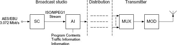
With the introduction of terrestrial digital broadcasting, the quality standards of a compact disc will be achieved for mobile and stationary reception of radio signals [Ple91]. Therefore, the data rate of a two-channel AES/EBU signal from a transmitting studio is reduced with the help of a source coder [Bra94] (see Fig. 1.5). Following the source coder (SC), additional information (AI) like the type of program (music/speech) and traffic information is added. A multicarrier technique is applied for digital transmission to stationary and mobile receivers. At the transmitter, several broadcasting programs are combined in a multiplexer (MUX) to form a multiplex signal. The channel coding and modulation is carried out by a multi-carrier transmission technique (Coded Orthogonal Frequency Division Multiplex, [Ala87, Kam92, Kam93, Tui93]).

Figure 1.2 Digital sound studio.

Figure 1.3 N-channel sound mixing console.

The DAB receiver (Fig. 1.6) consists of the demodulator (DMOD), the demultiplexer (DMUX) and the source decoder (SD). The SD provides a linearly quantized PCM signal (Pulse Code Modulation). The PCM signal is fed over a Digital-to-Analog Converter (DA Converter) to an amplifier connected to loudspeakers.

For a more detailed description of the DAB transmission technique, an illustration based on filter banks is presented (see Fig. 1.7). The audio signal at a data rate of 768 kbit/s is decomposed into subbands with the help of an analysis filter bank (AFB). Quantization and coding based on psychoacoustic models are carried out within each subband. The data reduction leads to a data rate of 96–192 kbit/s. The quantized subband signals are provided with additional information (header) and combined together in a frame. This so-called ISO-MPEG1 frame [ISO92] is first subjected to channel coding (CC). Time-interleaving (TIL) follows and will be described later on. The individual transmitting programs are combined in frequency multiplex (frequency-interleaving FIL) with a synthesis filter bank (SFB) into one broad-band transmitting signal. The synthesis filter bank has several complex-valued input signals and one complex-valued output signal. The real-valued band-pass signal is obtained by modulating with ejΩct and taking the real part. At the receiver, the complex-valued base-band signal is obtained by demodulation followed by low-pass filtering. The complex-valued analysis filter bank provides the complex-valued band-pass signals from which the ISO-MPEG1 frame is formed after frequency and time deinterleaving and channel decoding. The PCM signal is combined using the synthesis filter bank after extracting the subband signals from the frame.

Figure 1.7 Filter banks within DAB.
DAB Transmission Technique. The special problems of mobile communications are dealt with using a combination of the OFDM transmission technique with DPSK modulation and time and frequency interleaving. Possible disturbances are minimized by consecutive channel coding. The schematic diagram in Fig. 1.8 shows the relevant subsystems.
For example, the transmission of a program P1 which is delivered as an ISO-MPEG1 stream is shown in Fig. 1.8. The channel coding doubles the data rate. The typical characteristics of a mobile communication channel like time and frequency selectivity are handled by using time and frequency interleaving with the help of a multicarrier technique.

Figure 1.8 DAB transmission technique.
The burst disturbances of consecutive bits are reduced to single bit errors by spreading the bits over a longer period of time. The narrow-band disturbances affect only individual carriers by spreading the transmitter program P1 in the frequency domain, i.e. distribution of transmitter programs of carrier frequencies at a certain displacement. The remaining disturbances of the mobile channel are suppressed with the help of channel coding, i.e. by adding redundancy, and decoding with a Viterbi decoder. The implementation of an OFDM transmission is discussed in the following.
OFDM Transmission. The OFDM transmission technique is shown in Fig. 1.9. The technique stands out owing to its simple implementation in the digital domain. The data sequence ct(k) which is to be transmitted, is written blockwise into a register of length 2M. The complex numbers from d1(m) to dM(m) are formed from two consecutive bits (dibits). Here the first bit corresponds to the real part and the second to the imaginary part. The signal space shows the four states for the so-called QPSK [Kam92a, Pro89]. The vector d(m) is transformed with an inverse FFT (Fast Fourier Transform) into a vector e(m) which describes the values of the transmitted symbol in the time domain. The transmitted symbol xt(n) with period Tsym is formed by the transmission of the M complex numbers ei(m) at sampling period TS. The real-valued band-pass signal is formed at high frequency after DA conversion of the quadrature signals, modulation by ejΩct and by taking the real part. At the receiver, the transmitted symbol becomes a complex-valued sequence xr(n) by demodulation with e−jΩct and AD conversion of the quadrature signal. M samples of the received sequence xr(n) are distributed over the M input values fi(m) and transformed into the frequency domain with the help of FFT. The resulting complex numbers gi(m) are again converted to dibits and provide the received sequence cr(k). Without the influence of the communication channel, the transmitted sequence can be reconstructed exactly.
OFDM Transmission with a Guard Interval. In order to describe the OFDM transmission with a guard interval, the schematic diagram in Fig. 1.10 is considered. The transmission of a symbol of length M over a channel with impulse response h(n) of length L leads to a received signal y(n) of length M + L − 1. This means that the received symbol is longer than the transmitted signal. The exact reconstruction of the transmitted symbol is disturbed because of the overlapping of received symbols. Reconstruction of the transmitted symbol is possible by cyclic continuation of the transmitted symbol. Here, the complex numbers from the vector e(m) are repeated so as to give a symbol period of Tsym = (M + L)TS. Each of the transmitted symbols is, therefore, extended to a length of M + L. After transmission over a channel with impulse response of length L, the response of the channel is periodic with length M. After the initial transient state of the channel, i.e. after the L samples of the guard interval, the following M samples are written into a register. Since a time delay occurs between the start of the transmitted symbol and the sampling shifted by L displacements, it is necessary to shift the sequence of length M cyclically by L displacements. The complex values gi(m) do not correspond to the exact transmitted values di(m) because of the transmission channel h(n). However, there is no influence of neighboring carrier frequencies. Every received value gi(m) is weighted with the corresponding magnitude and phase of the channel at the specific carrier frequency. The influence of the communication channel can be eliminated by differential coding of consecutive dibits. The decoding process can be done according to ![]() . The dibit corresponds to the sign of the real and imaginary parts. The DAB transmission technique presented stands out owing to its simple implementation with the help of FFT algorithms. The extension of the transmitted symbol by a length L of the channel impulse response and the synchronization to collect the M samples out of the received symbol have still to be carried out. The length of the guard interval must be matched to the maximum echo delay of the multipath channel. Owing to differential coding of the transmitted sequence, an equalizer at the receiver is not necessary.
. The dibit corresponds to the sign of the real and imaginary parts. The DAB transmission technique presented stands out owing to its simple implementation with the help of FFT algorithms. The extension of the transmitted symbol by a length L of the channel impulse response and the synchronization to collect the M samples out of the received symbol have still to be carried out. The length of the guard interval must be matched to the maximum echo delay of the multipath channel. Owing to differential coding of the transmitted sequence, an equalizer at the receiver is not necessary.

Digital Radio Mondiale (DRM)
In the interest of national and international broadcasting stations a more widespread program delivery across regional or worldwide regions is of specific importance. This is accomplished by analog radio transmission in the frequency range below 30 MHz. The limited audio quality of the amplitude modulation technique (channel bandwidth 9–10 kHz) with an audio bandwidth of 4.5 kHz leads to a low acceptance rate for such kind of audio broadcasting. The introduction of the digital transmission technique Digital Radio Mondiale3 will replace the existing analog transmission systems. The digital transmission is based on OFDM and the audio coding MPEG4-AAC in combination with SBR (Spectral Band Replication).

Figure 1.10 OFDM transmission with a guard interval.
Internet Audio
The growth of the internet offers new distribution possibilities for information, but especially for audio and video signals. The distribution of audio signals is mainly driven by the MP3 format (MPEG-1 Audio Layer III [Bra94]) or in proprietary formats of different companies. The compressed transmission is used because the data rate of home users is still low compared to lossless audio and video formats. Since the transmission is based on file transfer of packets, the data rates strongly depend on the providing server, the actual internet traffic and the access point of the home computer. A real-time transfer of high-quality music is still not possible. If the audio compression is high enough to achieve a just acceptable audio quality, a real-time transfer with a streaming technology is possible, since the file size is small and a transmission needs less time (see Fig. 1.11). For this a receiver needs a double memory filled with incoming packets of a coded audio file and a parallel running audio decoding. After decoding of a memory with a sufficiently long audio portion the memory is transferred to the sound card of the computer. During sound playback of the decoded audio signal further incoming packets are received and decoded. Packet loss can lead to interrupts in the audio signal. Several techniques for error concealment and protocols allow the transfer of coded audio.

Figure 1.11 Audio streaming via the internet.
1.3 Storage Media
Compact Disc
The technological advances in the semiconductor industry have led to economical storage media for digitally encoded information. Independently of developments in the computer industry, the compact disc system was introduced by Philips and Sony in 1982. The storage of digital audio data is carried out on an optical storage medium. The compact disc operates at a sampling rate of fS = 44.1 kHz.4 The essential specifications are summarized in Table 1.1.
R-DAT (Rotary-head Digital Audio on Tape)
The R-DAT system makes use of the heliscan method for two-channel recording. The available devices enable the recording of 16-bit PCM signals with all three sampling rates (Table 1.2) on a tape. R-DAT recorders are used in studio recording as well as in consumer applications.
MiniDisc and MP3 Format
Advanced coding techniques are based on psychoacoustics for data reduction. A widespread storage system is the MiniDisc by Sony. The Mini Disc system operates with the ATRAC technique (Adaptive Transform Acoustic Coding, [Tsu92]) and has a data rate of about 2 · 140 kbit/s for a stereo channel. A magneto-optical storage medium is used for recording. The MP3 format was developed simultaneously, but the availability of recording and playback systems has taken a longer time. Simple MP3 recorders and playback systems are now available for the consumer market.
Table 1.1 Specifications of the CD system [Ben88].
| Type of recording | |
| Signal recognition | Optical |
| Storage density | 682 Mbit/in2 |
| Audio specification | |
| Number of channels | 2 |
| Duration | Approx. 60 min. |
| Frequency range | 20–20 000 Hz |
| Dynamic range | > 90 dB |
| THD | < 0.01% |
| Signal format | |
| Sampling rate | 44.1 kHz |
| Quantization | 16-bit PCM (2's complement) |
| Pre-emphasis | None or 50/15 µs |
| Error Correction | CIRC |
| Data rate | 2.034 Mbit/s |
| Modulation | EFM |
| Channel bit rate | 4.3218 Mbit/s |
| Redundancy | 30% |
| Mechanical specification | |
| Diameter | 120 mm |
| Thickness | 1.2 mm |
| Diameter of the inner hole | 15 mm |
| Program range | 50–116 mm |
| Reading speed | 1.2–1.4 m/s |
| 500–200 r/min. |
Super Audio Compact Disc (SACD)
The SACD was specified by Philips and Sony in 1999 as a further development of the compact disc with the objective of improved sound quality. The audio frequency range of 20 kHz is perceived as a limiting audio quality factor by some human beings, and the anti-aliasing and reconstruction filters may lead to ringing resulting from linear phase filters. This effect follows from short audio pulses leading to audible transients of the filters. In order to overcome these problems the audio bandwidth is extended to 100 kHz and the sampling frequency is increased to 2.8224 MHz (64 × 44.1 kHz). With this the filter specifications can be met with simple first-order filters. The quantization of the samples is based on a 1-bit quantizer within a delta-sigma converter structure which uses noise shaping (see Fig. 1.12). The 1-bit signal with 2.8224 MHz sampling frequency is denoted a DSD signal (Direct Stream Digital). The DA conversion of a DSD signal into an analog signal is accomplished with a simple analog first-order low-pass. The storage of DSD signals is achieved by a special compact disc (Fig. 1.13) with a CD layer in PCM format and an HD layer (High Density) with a DVD 4.38 GByte layer. The HD layer stores a stereo signal in 1-bit DSD format and a 6-channel 1-bit signal with a lossless compression technique (Direct Stream Transfer DST) [Jan03]. The CD layer of the SACD can be replayed with a conventional CD player, whereas special SACD players can replay the HD layer. An extensive discussion of 1-bit delta-sigma techniques can be found in [Lip01a, Lip01b, Van01, Lip02, Van04].
Table 1.2 Specifications of the R-DAT system [Ben88].
| Type of recording | |
| Signal recognition | Magnetic |
| Storage capacity | 2 GB |
| Audio specification | |
| Number of channels | 2 |
| Duration | Max. 120 min. |
| Frequency range | 20–20 000 Hz |
| Dynamic range | > 90 dB |
| THD | < 0.01% |
| Signal format | |
| Sampling rate | 48, 44.1, 32 kHz |
| Quantization | 16-bit PCM (2's complement) |
| Error correction | CIRC |
| Channel coding | 8/10 modulation |
| Data rate | 2.46 Mbit/s |
| Channel bit rate | 9.4 Mbit/s |
| Mechanical specification | |
| Tapewidth of magnet | 3.8 mm |
| Thickness | 13 µm |
| Diameter of head drum | 3 cm |
| Revolutions per min. | 2000 r/min. |
| Rel. track speed | 3.133 m/s |
| 500–200 r/min. |
![]()

Figure 1.13 Layer of the SACD.
Digital Versatile Disc – Audio (DVD-A)
To increase the storage capacity of the CD the Digital Versatile Disc (DVD) was developed. The physical dimensions are identical to the CD. The DVD has two layers with one or two sides, and the storage capacity per side has been increased. For a one-sided version for audio applications the storage capacity is 4.7 GB. A comparison of specifications for different disc media is shown in Table 1.3. Besides stereo signals with different sampling rates and word-lengths a variety of multi-channel formats can be stored. For data reduction a lossless compression technique, MLP (Meridian Lossless Packing), is applied. The improved audio quality compared to the CD audio is based on the higher sampling rates and word-lengths and the multichannel features of the DVD-A.
Table 1.3 Specifications of CD, SACD and DVD-A.

1.4 Audio Components at Home
Domestic digital storage media are already in use, like compact discs, personal computers and MP3 players, which have digital outputs, and can be connected to digital postprocessing systems right up to the loudspeakers. The individual tone control consists of the following processing.
Equalizer
Spectral modification of the music signal in amplitude and phase and the automatic correction of the frequency response from loudspeaker to listening environment are desired.
Room Simulation
The simulation of room impulse responses and the processing of music signals with special room impulse response are used to give an impression of a room like a concert hall, a cathedral or a jazz club.
Surround Systems
Besides the reproduction of stereo signals from a CD over two frontal loudspeakers, more than two channels will be recorded in the prospective digital recording systems [Lin93]. This is already illustrated in the sound production for cinema movies where, besides the stereo signal (L, R), a middle channel (M) and two additional room signals (LB, RB) are recorded. These surround systems are also used in the prospective digital television systems. The ambisonics technique [Ger85] is a recording technique that allows three-dimensional recording and reproduction of sound.
Digital Amplifier Concepts
The basis of a digital amplifier is pulse width modulation as shown in Fig. 1.14. With the help of a fast counter, a pulse width modulated signal is formed out of the w-bit linearly quantized signal. Single-sided and double-sided modulated conversion are used and they are represented by two and three states, respectively. Single-sided modulation (2 states, −1 and +1) is performed by a counter which counts upward from zero with multiples of the sampling rate. The number range of the PCM signal from −1 to +1 is directly mapped onto the counter. The duration of the pulse width is controlled by a comparator. For pulse width modulation with three states (−1, 0, +1), the sign of the PCM signal determines the state. The pulse width is determined by a mapping of the number range from 0 to 1 onto a counter. For double-sided modulation, an upward/downward counter is needed which has to be clocked at twice the rate compared with single-sided modulation. The allocation of pulse widths is shown in Fig. 1.14. In order to reduce the clock rate for the counter, pulse width modulation is carried out after oversampling (Oversampling) and noise shaping (Noise Shaping) of the quantization error (see Fig. 1.15, [Gol90]). Thus the clock rate of the counter is reduced to 180.6 MHz. The input signal is first upsampled by a factor of 16 and then quantized to 8-bits with third-order noise shaping. The use of pulse shaping with delta-sigma modulation is shown in Fig. 1.16 [And92]. Here a direct conversion of the delta-sigma modulated 1-bit signal is performed. The pulse converter shapes the envelope of the serial data bits. The low-pass filter reconstructs the analog signal. In order to reduce nonlinear distortion, the output signal is fed back (see Fig. 1.17, [Klu92]). New methods for the generation of pulse width modulation try to reduce the clock rates and the high frequency components [Str99, Str01].

Figure 1.14 Pulse width modulation.

Figure 1.15 Pulse width modulation with oversampling and noise shaping.

Figure 1.16 Pulse shaping after delta-sigma modulation.

Figure 1.17 Delta-sigma modulated amplifier with feedback.
Digital Crossover
In order to perform digital crossovers for loudspeakers, a linear phase decomposition of the signal with a special filter bank [Zöl92] is done (Fig. 1.18). In a first step, the input signal is decomposed into its high-pass and low-pass components and the high-pass signal is fed to a DAC over a delay unit. In the next step, the low-pass signal is further decomposed. The individual band-pass signals and the low-pass signal are then fed to the respective loudspeaker. Further developments for the control of loudspeakers can be found in [Kli94, Kli98a, Kli98b, Mül99].

Figure 1.18 Digital crossover (FSi frequency splitting, TCi transition bandwidth control, DELi delay).
References
[AES91] AES10-1991 (ANSI S4.43-1991): AES Recommended Practice for Digital Audio Engineering – Serial Multichannel Audio Digital Interface (MADI).
[AES92] AES3-1992 (ANSI S4.40-1992): AES Recommended Practice for Digital Audio Engineering – Serial Transmission Format for Two-Channel Linearly Represented Digital Audio.
[Ala87] M. Alard, R. Lasalle: Principles of Modulation and Channel Coding for Digital Broadcasting for Mobile Receivers, EBU Review, No. 224, pp. 168–190, August 1987.
[And92] M. Andersen: New Principle for Digital Audio Power Amplifiers, Proc. 92nd AES Convention, Preprint No. 3226, Vienna, 1992.
[Ben88] K. B. Benson: Audio Engineering Handbook, McGraw-Hill, New York, 1988.
[Bra94] K. Brandenburg, G. Stoll: ISO/MPEG-1 Audio: A Generic Standard for Coding of High Quality Digital Audio, J. Audio Eng. Soc., Vol. 42, No. 10, pp. 780–792, October 1994.
[Ger85] M. A. Gerzon: Ambisonics in Multichannel Broadcasting and Video, J. Audio Eng. Soc., Vol. 33, No. 11, pp. 859–871, November 1985.
[Gol90] J. M. Goldberg, M. B. Sandler: New Results in PWM for Digital Power Amplification, Proc. 89th AES Convention, Preprint No. 2959, Los Angeles, 1990.
[Hoe01] W. Hoeg, T. Lauterbach: Digital Audio Broadcasting, John Wiley & Sons Ltd, Chichester, 2001.
[ISO92] ISO/IEC 11172-3: Coding of Moving Pictures and Associated Audio for Digital Storage Media at up to 1.5 Mbits/s – Audio Part, International Standard, 1992.
[Jan03] E. Janssen, D. Reefman: Super Audio CD: An Introduction, IEEE Signal Processing Magazine, pp. 83–90, July 2003.
[Kam92] K. D. Kammeyer, U. Tuisel, H. Schulze, H. Bochmann: Digital Multicarrier-Transmission of Audio Signals over Mobile Radio Channels, Europ. Trans. on Telecommun. ETT, Vol. 3, pp. 243–254, May–June 1992.
[Kam93] K. D. Kammeyer, U. Tuisel: Synchronisationsprobleme in digitalen Multiträgersystemen, Frequenz, Vol. 47, pp. 159–166, May 1993.
[Kli94] W. Klippel: Das nichtlineare Übertragungsverhalten elektroakustischer Wandler, Habilitationsschrift, Technische Universität Dresden, 1994.
[Kli98a] W. Klippel: Direct Feedback Linearization of Nonlinear Loudspeaker Systems, J. Audio Eng. Soc., Vol. 46, No. 6, pp. 499–507, 1998.
[Kli98b] W. Klippel: Adaptive Nonlinear Control of Loudspeaker Systems, J. Audio Eng. Soc., Vol. 46, No. 11, pp. 939–954, 1998.
[Klu92] J. Klugbauer-Heilmeier: A Sigma Delta Modulated Switching Power Amp, Proc. 92nd AES Convention, Preprint No. 3227, Vienna, 1992.
[Lec92] D. Leckschat: Verbesserung der Wiedergabequalität von Lautsprechern mit Hilfe von Digitalfiltern, Dissertation, RWTH Aachen, 1992.
[Lin93] B. Link, D. Mandell: A DSP Implementation of a Pro Logic Surround Decoder, Proc. 95th AES Convention, Preprint No. 3758, New York, 1993.
[Lip01a] S. P. Lipshitz, J. Vanderkooy: Why 1-Bit Sigma-Delta Conversion is Unsuitable for High-Quality Applications, Proc. 110th Convention of the Audio Engineering Society, Preprint No. 5395, Amsterdam, 2001.
[Lip01b] S. P. Lipshitz. J. Vanderkooy: Towards a Better Understanding of 1-Bit Sigma-Delta Modulators – Part 2, Proc. 111th Convention of the Audio Engineering Society, Preprint No. 5477, New York, 2001
[Lip02] S. P. Lipshitz, J. Vanderkooy: Towards a Better Understanding of 1-Bit Sigma-Delta Modulators – Part 3, Proc. 112th Convention of the Audio Engineering Society, Preprint No. 5620, Munich, 2002.
[Mül99] S. Müller: Digitale Signalverarbeitung für Lautsprecher, Dissertation, RWTH Aachen, 1999.
[Ple91] G. Plenge: DAB – Ein neues Hörrundfunksystem – Stand der Entwicklung und Wege zu seiner Einführung, Rundfunktechnische Mitteilungen, Vol. 35, No. 2, pp. 46–66, 1991.
[Str99] M. Streitenberger, H. Bresch, W. Mathis: A New Concept for High Performance Class-D Audio Amplification, Proc. AES 106th Convention, Preprint No. 4941, Munich, 1999.
[Str01] M. Streitenberger, F. Felgenhauer, H. Bresch, W. Mathis: Zero Position Coding (ZePoC) – A Generalised Concept of Pulse-Length Modulated Signals and its Application to Class-D Audio Power Amplifiers, Proc. AES 110th Convention, Preprint No. 5365, Amsterdam, 2001.
[Tsu92] K. Tsutsui, H. Suzuki, O. Shimoyoshi, M. Sonohara, K. Akagiri, R. Heddle: ATRAC: Adaptive Transform Coding for MiniDisc, Proc. 91st AES Convention, Preprint No. 3216, New York, 1991.
[Tui93] U. Tuisel: Multiträgerkonzepte für die digitale, terrestrische Hörrundfunkübertragung, Dissertation, TU Hamburg-Harburg, 1993.
[Van01] J. Vanderkooy, S. P. Lipshitz: Towards a Better Understanding of 1-Bit Sigma-Delta Modulators – Part 1, Proc. 110th Convention of the Audio Engineering Society, Preprint No. 5398, Amsterdam, 2001.
[Van04] J. Vanderkooy, S. P. Lipshitz: Towards a Better Understanding of 1-Bit Sigma-Delta Modulators – Part 4, Proc. 116th Convention of the Audio Engineering Society, Preprint No. 6093, Berlin, 2004.
[Zöl92] U. Zölzer, N. Fliege: Logarithmic Spaced Analysis Filter Bank for Multiple Loudspeaker Channels, Proc. 93rd AES Convention, Preprint No. 3453, San Francisco, 1992.