Fire protection is probably one of the least mentioned features in Revit. Fire protection designers use a variety of methods and software to lay out fire protection systems. There are considerable benefits to doing this process in Revit MEP 2011, including the coordination and clash detection with other services and building elements.
In this chapter, you will learn how to:
Place fire protection equipment
Create a wet fire protection system
Route fire protection piping
Proper planning of placing fire protection equipment is essential when trying to create a productive layout with Revit MEP 2011. You should plan to have most of your equipment spotted during the schematic design phase of the project, which helps with productivity and coordination with other disciplines. You will need to use proper design methods to verify whether a fire pump is required on a project.
Although pump manufacturers are starting to provide Revit content, they are still few and far between. If you look under Fire Protection
You will want to start your model by understanding where your water supply starts. Normally the architects will provide location details, and you can then display this information in your design model by either creating a water meter family or modifying an end cap family. To modify an existing family to indicate the water inlet point, do the following:
Open the
Chapter16_Dataset.rvtfile found onwww.wiley.com/go/masteringrevitmep2011.In the Project Browser, scroll down to the Families section, expand the Pipe Fittings category, and select Cap – Generic.
Right-click the family, and select Edit. This opens the Family Editor.
Click the Revit Home button, and select Save As

Edit the newly created family by changing the family type from Pipe Fitting to Mechanical Equipment, located under Modify
Once the family is complete, select Family Types, and add three new parameters: Static Pressure, Residual Pressure, and Gallons Per Minute.
When creating these new parameters, be sure to use the piping discipline and appropriate units. Also, determine whether shared parameters would be applicable in this situation (see Chapter 19 for more information). You can leave the end cap the way it is modeled, or you can use model lines with an ellipse to create a break line to show up in single line piping, as in Figure 16.1.
Select the connector, and change its type from Fitting to Fire Protection Wet.
Any existing line work can either be deleted or be changed to Invisible.

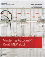
You should try to preassemble as much of the fire protection components as possible to help with production time. Figure 16.2 shows a fire pump preassembled so one would only have to change out certain components, such as changing the pump for a smaller or larger pump depending on what the calculated fire flow demand calls for.
To create a preassembled fire pump, do the following:
Save a Revit file named
pump assembly model.Connect as much of the pump assembly as possible, taking into account where most of the components will likely be placed. You can use a split case pump that comes with Revit MEP as your base fire pump. This will normally give a large enough footprint once every piece has been assembled, but always verify the size of the equipment with the manufacturer's cut sheets to keep from making a costly mistake.
You can use an inline pump to represent a jockey pump, because you will find it matches closely in size. The inline pump is located under Imperial Library
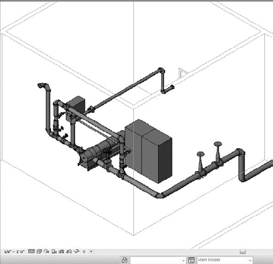
Some of the harder items to find information about are the control panels because of proprietary components. For these, you can create a family using an Electrical Equipment family type. Another option for showing the control panel is to show it as an in-place component (see Figure 16.3).
This would be used as a placeholder to assure that the control panel is accounted for and so that electrical information may be added later through a electrical connector located by the electrical engineer.
Once you have your layout the way you want it, you can save the model for future use. Select the elements required, and click Create Group. When prompted for a name, be sure to give it a suitable one — for example,
Fire Alarm Pump Set, notGroup 130.Here the group insertion point can be modified and then saved as a library group. This can then either be loaded as a model group or be linked and bound.
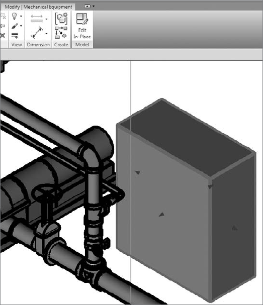
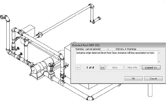
Using the link method will give far more flexibility when positioning this object — as long as it is subsequently bound to allow access to the connections. Be aware that any hosted families used in this process will lose their associated host and will require rehosting.
The copy-and-paste method will give you a warning (see Figure 16.4), while the link-and-bind method will not. It is left to the user to check elements for hosting, although they retain their location properties correctly.
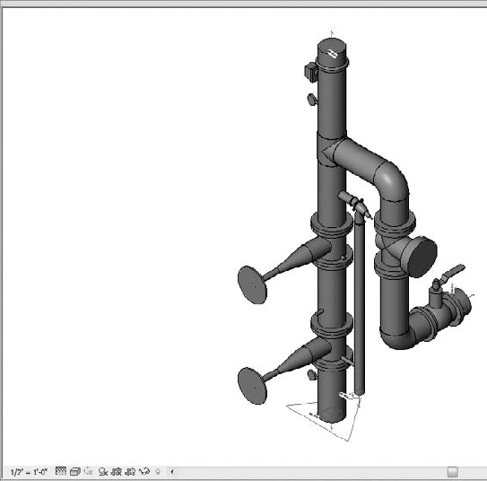
Fire risers for most small projects are typically assembled in the same manner most of the time. The ideal way to handle assemblies like this would be to create the family as Mechanical Equipment. The reason for this is that during schematic design, placing the fire riser is crucial for understanding where the fire line will need to be routed (see Figure 16.5).
This family is created by nesting pipe fitting and pipe accessories families. To review what components make up this family, do the following:
Open 6
Inch Fire Riser.rfalocated atwww.wiley.com/go/masteringrevitmep2011.There are several different pipe fittings and pipe accessories families that are nested into this family and that make up the riser. They are as follows:
Pipe Elbow.rfa, Pipe Tee.rfa, Alarm Pressure Switch.rfa, Ball Valve - 2.5-6 Inch.rfa, Check Valve - 2-12 Inch - Flanged.rfa, Double Check Valve - 2.5-10 Inch.rfa, Multi-Purpose Valve - Angle - 1.5-2.5 Inch - Threaded.rfa, andPlug Valve - 0.5-2 Inch.rfa. You can insert these from the Pipe Fitting and Pipe Accessories directory located in the Imperial Library.When placing the fittings together, make sure to align, lock, and dimension each fitting together. If you leave out this step, the fittings will pull apart if you add parameters to make them flex. Refer to Figure 16.6.
Since system piping cannot be routed in the Family Editor, you will need to create extrusions for the piping sections and then just add the fire protection connectors. When adding the connectors, make sure the arrows are pointed in the direction of connection.

By assembling the riser together, you can coordinate the location it was be installed in and then start planning how to route your piping.
Since you now know about fire pump assemblies and how to create a standard fire riser, you will start planning for the type fire protection sprinkler heads you will need to use for your model. Within Revit MEP 2011, there are several different types of sprinkler heads to choose from. The different family types of sprinkler heads are hosted and nonhosted.
Hosted sprinkler heads are normally face-based families. When using these types of families, you will need to locate them on a surface. These locations depend upon the installation and the type of sprinklers, which could be Wall, Ceiling, Slab, or Soffit mounted. These surfaces can be part of the linked architectural model or walls/ceilings that have been created in your file using the tools located on the Architects tab.
A Strategy for Sprinkler Heads
You can use the reflected ceiling of a linked architectural model to coordinate the location of your sprinkler heads and to provide a surface for them to mount to by creating a fire protection ceiling plan. Type VG while in the model view or select View
Nonhosted sprinkler families must have the offset height parameter set to locate the heads at the proper elevation (see Figure 16.7).

Upright sprinkler heads normally are nonhosted because they are located in spaces that do not have ceilings such as storage rooms or mechanical closets. If you do not set the offset height, then the heads will come in at a default of 0', which could locate the heads on or below the floor level.
There are several options for the type fire protection systems that can be created. They are as follows:
- Fire protection
This can be used for the building sprinkler piping, or it can be used for the utility fire protection coming into your building to connect the base of your fire protection riser.
- Wet fire protection
This pipe system type normally is used for the layout of the piping from the riser to the sprinkler head layout.
- Dry fire protection
This pipe system is used for layout from the fire riser to the sprinkler head or standpipe to keep the system from freezing.
- Preaction
This pipe system can also be used for a deluge system.
- Fire protection other
This pipe system can be used for a glycol antifreeze system and also can be used for a chemical suppression system.
You can also refer to piping systems in Chapter 8 for more information. When creating a fire protection system, one thing to remember is that the system will not calculate and autosize like domestic water systems will. The main reason is that fire protection systems have no true way of selecting and calculating which heads are in the highest demand.
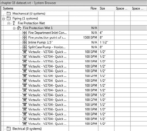
John's employer has just came back from a meeting with a high-profile client and has sold their ability to produce a fire protection model in BIM. His employer has stated that the client wants to see the total of flow for the highest demand on the system so their building can pass the fire inspection requirements as mandated by the local fire marshal. John has already calculated the system load so he knows where the highest demand shall be located. John decides that the easy way to accomplish this is to add calc-gpm in the comments parameters of the sprinkler heads and then filter these heads through a schedule with a grand total of GPM. The inspector reviewed the schedule and approved the client's building, and a satisfied client paid the bill.
To replicate what John did, you can do the following:
Select the sprinkler heads that need to be modified, and add
calc-gpminto thecommentsparameters.
Go to the Analyze tab on the ribbon, and then select Schedule/Quantities, which will open the Schedule dialog box. Select Sprinklers from the Category group, and then select OK.

Next select Flow And Comments from the Available Fiel ds dialog box, and add it to the Schedule Fields (In Order) dialog box. Then click OK, which will create your schedule.

Now that you have the sprinkler schedule, you want to total only the sprinklers with comments. To do this, there are several parameters you have to set.
First go to Properties browser, select Filter tab, and then change the filter to Comments.
Set the parameter equals to
calc-gpm.Select Sorting/Grouping, and change the Sort By pull-down menu to Comments.
Select Itemize Every Instance.
Select Grand Totals while selecting Totals Only.
Select the Formatting tab, highlight Flow, and check Calculate Totals. Next highlight Comments, and select Hidden Fields.
Now your schedule will show only the items you want to show up, including the total GPM flow.

If the system were to try to calculate by GPM, it would account for every sprinkler head on the system, which would grossly oversize the system. Also, the fire protection system at this time has no effective way of calculating the water pressure as it goes higher in elevation.
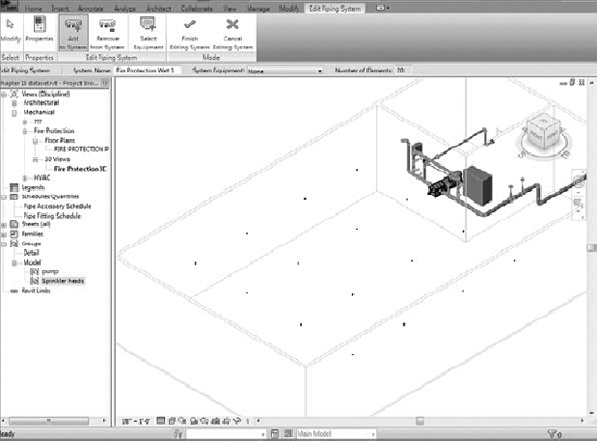
When creating a fire protection wet system or one of the systems previously mentioned, you will first want to select all the components that are going to be associated with that system (see Figure 16.8).
In case a system has already been started, you can add to the system by selecting a component on the system. Click Piping Systems
Once your fire protection system is created, you will need to make sure the piping will filter correctly. Using filters correctly (that is, by assigning colors and line types to piping) will help keep your systems organized. To create a fire protection filter, do the following:
On the View tab, select Visibility/Graphics
Click Edit/New, which will open the Filter Settings dialog box. You should notice that there are a number of filters already created. Select the Domestic Hot Water filter, right-click, and select Duplicate. Right-click again, and rename the filter to the type piping system you are filtering. In the right corner, you will see a dialog box named Filtering Rules. Change the rule from System Type to System Name. Refer to Figure 16.10.
Rename Domestic Hot Water 1 to Fire Protection (or whatever you named your system), select Apply, and close. Now you will see the Visibility Graphics dialog box with the Filters tab. Select Add, and you should see the newly created filter. Refer to Figure 16.11.


Deciding what colors and line types you want for the fire protection will most likely come from existing CAD standards. Once the filters are created and applied to the views, save them as view templates, and load them into the main templates. This will add to the ease of completing a design in an efficient manner.
When setting up piping to route, you will want to apply the proper pipe material. There are several areas you will have to adjust to set this up properly. These areas are system pipes, fittings, pipe material, pipe sizing tables, and fluids table. Once you set these areas, you can then concentrate on the autorouting and manual routing of pipe.
- System pipes
These are the pipes that are hard-coded into Revit. You have a limited amount of freedom to adjust parameters for these system families.
- Fittings
These can be applied to the parameters of the system pipes, which will allow for fittings to populate the model automatically. The fitting must be loaded into the model for them to work.
- Pipe material
This is set by selecting Mechanical Settings
- Pipe sizing table
This is set by selecting Mechanical Settings
- Fluids table
This is set by selecting Mechanical Settings
So, what do you do if you require special fittings? It's quite common to see mechanical joints required on fire protection systems. Since they do not exist in the out-of-box content of Revit MEP 2011, you are stuck with three choices.
First, you can use regular fittings and then copy and rename them to the type fittings you need, as was demonstrated the fire pump. Then you can just use schedules to count the number and make of fittings.
Second, you could create your own, that is, if you have the budget to create every fitting you need (even though it is worth it in the long haul).
Third is to find a manufacturer that has already developed their content. As luck would have it, Victaulic has most if not all of their products in Revit on its website at www.victaulic.com. You can download them and load the fittings you need for your layout. Once they are loaded into your model, duplicate your system piping material, and apply the fittings as needed (refer to Figure 16.12).

Now you should be ready to route piping. Select one of the sprinkler heads that you have added to the fire protection system, and then press the Tab key a couple of times until the autorouting features highlight its suggested path. Or you can select Generate Layout under Modify Sprinklers. (Refer to Figure 16.13.)
You have four options to select for generating the layout: Network, Perimeter, Intersections, and Custom. Each one has several routing solutions to choose from.
- Network
This solution creates a bounding box around the components selected for the piping system and then bases several solutions on a main segment along the center line for the bounding box, with branches coming from the main segment.
- Perimeter
This solution creates a bounding box around the components selected for the system and proposes several potential routing solutions. You can specify the Inset value that determines the offset between the bounding box and the components. Inset is available only when the Perimeter option is selected.
- Intersections
This solution bases the potential routing on a pair of imaginary lines extending from each connector for the components in the system. Perpendicular lines extend from the connectors. Where the lines from the components intersect are potential junctions in the proposed solutions along the shortest paths.
- Custom
The solution becomes available once you begin to modify any of the other solutions.

Autorouting is great for generating layouts very quickly, but it may not give you ideal results and could lead to substantial rework. There are a variety of options for splitting and redirecting main runs, but these tools do require some practice.
The manual routing of piping will give you the missing control. When routing, manually start your piping at the elevation that you know will be most likely out of the way of other disciplines. Cutting sections when routing piping can really improve the success of your coordination of your Revit model. Lay out the mains first, ensuring that most of the piping fits. Then work on connecting the heads to the mains. The adage of "measure twice, cut once" still applies. Taking a few minutes to review structural, mechanical and architectural models can really cut down on modeling time. After you coordinate and verify your routing, finish your layout. (Refer to Figure 16.14.)
If your systems were configured accurately, your piping will be filtered to the colors and line types selected.

- Placing fire protection equipment
When starting a fire protection model, placing the equipment can make or break your design. The ability of Revit to verify your layouts early, through the coordination of this equipment with other disciplines, can set the pace for a successful project.
- Master It
What is a method to help speed up production when using a standard fire riser on multiple buildings?
- Create fire protection systems
Creating proper fire protection systems is essential to the performance and behavior of the fire protection model. Properly created fire protection systems also help with being able to coordinate with other disciplines during design.
- Master It
Marty has just created a fire protection system name called Wet1, and he has created a filter system type named wet1. Now Marty is in a presentation, and his system is not filtering properly. What should he look at first? What should he do if there is a second problem?
- Route fire protection piping
Fire protection piping can be routed by a couple different methods. It can be set up with different materials to help with takeoffs and specifications. Once piping has been routed, it can be coordinated with other disciplines to reduce errors and omissions.
- Master It
What are some of the methods to deal with fittings that may not be supplied with Revit MEP 2011?