
There’s nothing quite so dull as the subject of studio wiring when all you want to do is make music, but if you don’t pay sufficient attention to this important topic, your system may not perform as well as it should, as we’ve confirmed on a number of our Studio SOS visits. Even plugging into the wrong mains sockets can cause unexpected problems, as can having too many or too few ground connections. To illustrate some of the typical problems and their solutions, we’ll start by examining some real-life examples we’ve encountered.
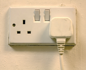
The importance of appropriate mains connections was very aptly demonstrated when we received a Studio SOS distress call from a reader whose audio system muted for a second or two whenever anyone switched on an appliance or even a light elsewhere in the house! We eventually traced the problem back to a digital mixer he was using for monitoring, fed from the digital output of his interface, and the mixer was upset whenever other electrical items were powered on, or the central heating boiler fired up. His studio system was powered from two wall sockets on opposite sides of the room. We weren’t sure whether these were connected to the same ringmain or whether they were on separate circuits, but problems can arise very easily when systems are powered from two or more different power points because the socket grounds take different paths to the main building ground point, potentially creating ‘ground loops’ which can induce mains-frequency hum into the system. (See p. 95)
The simple solution in this instance was to redo the studio powering arrangements so that the entire studio ran from just one wall socket. The amount of current taken by a typical project studio is far lower than the maximum capacity of one power socket, so there are no safety problems associated with doing this.
The amount of current drawn by a typical project studio is far lower than the maximum capacity of one domestic power socket, so there are no safety problems associated with running everything from a single outlet.
Our strategy was to fan out all the power points from this one socket using a surge-protected, six-way distribution board, which in turn fed a number of conventional four-way distribution boards to provide the necessary number of outlets for all the equipment. In effect, the mains power is distributed in a star arrangement, and the equipment mains safety grounds are all returned directly to the same wall socket via the shortest possible path. It makes sense to plug the most power-hungry devices into sockets as close to the wall outlet as possible.
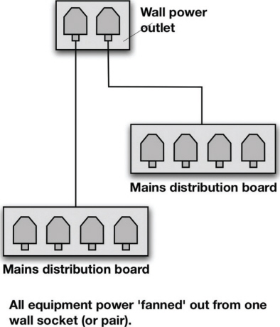
So long as you are not exceeding the current rating in any part of the chain, there’s nothing wrong with cascading power distribution boards from the same outlet in a star arrangement.
TIP : In analogue systems, ground loops are usually audible as unwanted background hums, buzzes or whining, but in digital systems the effects don’t always produce an audible artefact at all. Instead, they may simply compromise the way data is transferred from one device to another, resulting in occasional, unexplained clicks or drop-outs. Note that optical digital connections can’t create ground loops, although a loop may still be present in the system via other, wired connections.
Everything was re-connected to this new power system, including the keyboard and electronic drum kit, and when we retested it the hum-induced digital-dropout problem had vanished completely. No changes to the signal cabling were required, as there was very little signal wiring and the cables were very short, other than the feeds from the keyboard and an electronic drum kit.
TIP : All signals passing down a length of cable are analogue, even digital ones! Digital data is transmitted as a series of very brief analogue pulses, so if interference, noise or distortion becomes severe enough to prevent those pulses from being detected correctly at the receiving end, you have a problem. As with most things digital, you won’t know you have a problem until the level of interference starts to cause significant errors, and then you’ll suddenly find the audio is dropping out, or there are unexplained clicks and glitches.
TIP : If in doubt about the total power consumption of your system, add up the power consumption figures (in VA or Watts) for each device. The appropriate number should be listed on a plate near the mains connection on the units, or in their handbooks. Just make sure that the total comes to less than the maximum power rating for the mains wall socket. In the UK a standard 13-Amp mains outlet can supply up to 2990 Watts of power (13A x 230V), whilst a USA wall socket is good for between 1800 Watts (15A x 120V) and 2400 Watts, depending on if it is a 15- or 20-Amp outlet.
Ground loops can arise in any moderately complex audio system where there are multiple ground or earth paths between pieces of equipment and between the equipment and the mains power-supply safety earths. Take the example of a mixer connected via an unbalanced cable to a powered monitor, with both devices plugged into different mains wall sockets, several feet apart. The mains safety-earth connections from those two sockets are joined together at the building’s fuse box after many meters of cabling winding its way through the building. The ‘ground loop’ is completed by the signal-cable ground connecting the mixer and the monitor.
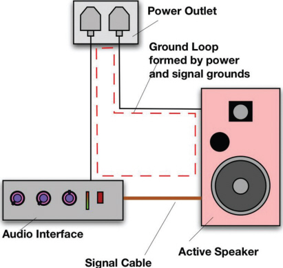
Ground loops can occur whenever there are multiple ground paths created by the signal cabling between items of equipment and their mains power-supply safety earths, causing audible hum and buzz, or digital instability.
Most equipment incorporates some form of mains filtering which dumps unwanted noise into the safety earth in the form of small ‘leakage’ currents. The small but finite resistance of the mains earth cabling means that the small leakage currents flowing along it generate a small and varying voltage across the entire earth cable, so that the actual voltage at the mains wall socket earth terminal might be slightly above the nominal 0 Volts. This has no bearing on the safety role of the socket’s earth terminal, but ground loops can become problematic when that voltage is allowed to couple back into the equipment’s audio circuitry, since it then becomes audible as hums or buzzes, or causes digital instability.
The surefire way of providing that coupling is to allow a current to flow in a closed circuit through the equipment’s audio grounds. In the example above, the loop exists between the earth of the first mains socket, through the plugged-in equipment, along the grounded unbalanced audio cable, through the connected equipment, down to another earthed mains socket, and then via the building’s wiring to the central earth termination where it then finds its way back up to the first mains socket to complete the loop!
If a system is fed from two or more power sockets that happen to be on different ring main circuits, as we suspect may have been the case in the preceding Studio SOS example, the size of the ground loop (or loops) may be many tens of metres, running all the way back to the fuse box or consumer unit. As a rule, the more cable in the ground loop, the larger the induced ground voltages and the better it is at picking up interference. Adopting a fan or star-shaped mains distribution system fed from a single power outlet helps to minimise ground-loop problems by keeping the ground paths as short as possible while also ensuring a common ground reference point.
Disconnecting one or more mains cable safety grounds may break a ground loop and appear to solve a hum problem, but it is most definitely not a good idea from the safety point of view. A serious equipment fault could well become lethal in such circumstances. Ground loops must only ever be resolved by interrupting the audio cable screen in some way, as will be explained shortly.
TIP: Don’t run signal cables alongside power cables, if at all possible, as this can also result in magnetically induced hum. If audio and power cables have to cross, making the crossings at right angles will minimise the possibility of interference.
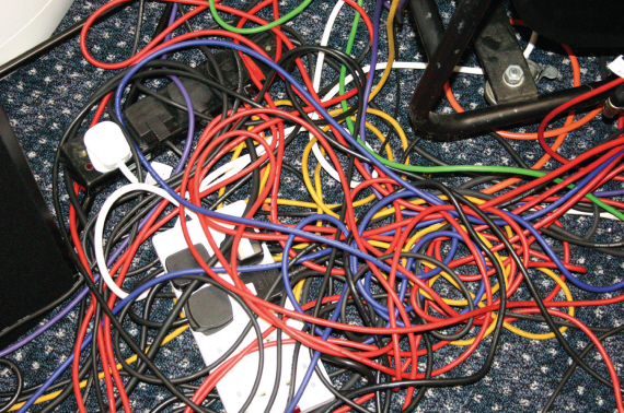
Keeping your mains and signal cable runs separate will not only assist when trying to diagnose a fault, but also reduce the possibility of accidentally inducing noise.
Case Study
We were asked to sort out a hum problem in a very simple recording setup comprising a Zoom hard disk recorder and an old Joe Meek compressor. The problem here was that whenever the owner plugged his guitar into the compressor to record it onto the Zoom multitrack machine he was greeted by a huge level of hum and other unwanted interference noises.
The problem turned out to be almost the opposite of a ground loop: there was no ground at all! Everything in his recording system was running from double-insulated (Class II) power supplies (wall warts and line lumps!), which incorporate isolating transformers, without a mains-ground connection anywhere. This meant that the whole system was ‘floating’ and the screens of all the connecting cables were effectively acting as radio aerials, picking up all sorts of unwanted rubbish from the ether and passing it all directly into the audio electronics.
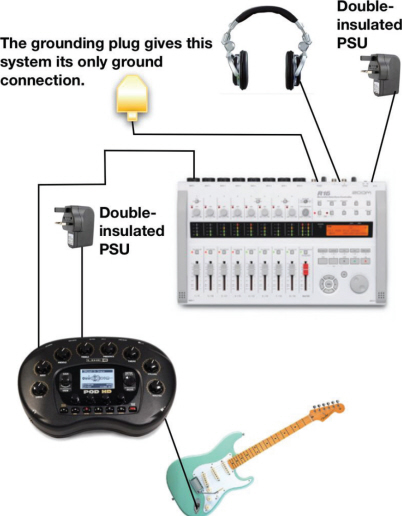
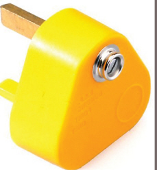
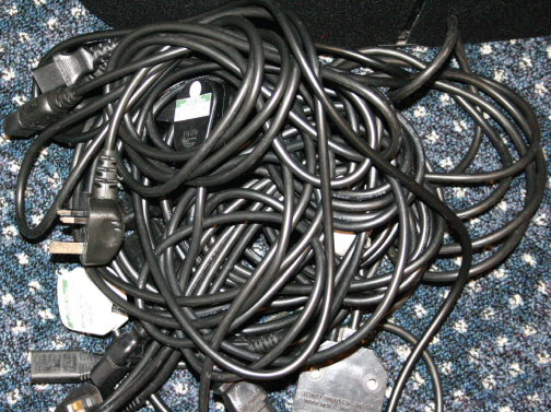
If everything in your recording system uses wall-wart or line-lump double-insulated (Class II) power supplies, which incorporate isolating transformers, you can end up without a mains-ground connection at all!, resulting in excessive hum. The problem can be solved using a dedicated grounding mains plug, such as the one opposite (note the model shown is for a UK 13A socket).
The solution was to attach a length of wire to the metalwork of the Zoom recorder via one of the screws on the underside, and to ground the other end to the metal chassis of a piece of household equipment that was properly grounded – in this case, a nearby hi-fi system. As soon as we did that the hum problem vanished entirely because the cable screens were then able to act as proper screens, trapping unwanted interference and passing it to ground rather than into the audio circuitry!
In theory you could create a ground cable by wiring only a ground wire to the earth pin of a standard three-pin plug, but we certainly don’t recommend this as tripping over the cable might just disconnect it from the ground pin in the plug and allow it to touch the live pin, which would then cause all the connected equipment to become electrically live. A far safer solution is to buy a dedicated grounding mains plug fitted with a metal ground pin and plastic dummy pins for the live and neutral. Although these are not stocked by typical DIY stores, an on-line search for “grounding mains plug” brought up several sources.
Balanced and Unbalanced
Audio-signal connections, including digital ones, can either be balanced or unbalanced. An unbalanced audio connection employs on a two-conductor cable, with an insulated inner core surrounded by a conductive screen, that also forms the return path for the audio. This is how a typical guitar cable is constructed. Although the screen (which is generally connected to ground within the connected devices) offers a degree of protection against electrostatic interference, it is still possible for traces of outside interference – especially electromagnetic interference – to become superimposed on the wanted audio signal, if the supposedly ground-potential screen starts to pass small AC currents (as can be the case when a ground-loop occurs). Although the current passed is far too small to be dangerous, it can result in the screen voltage being modulated sufficiently to cause audible hum.
In any system using unbalanced audio connections, it is inherently very difficult to keep the ground currents out of the audio circuitry, simply because the cable screen also functions as the signal-return path and any hum induced into the screen automatically becomes part of the signal.
Balanced systems were developed to allow audio signals to be carried over longer distances without being significantly affected by electrostatic or electromagnetic interference. The underlying concept is that instead of a two-conductor system that uses the same conductor as both screen and signal-return connection, as in an unbalanced connection, a balanced cable employs two ‘floating’ signal conductors (usually referred to as the ‘hot’ and ‘cold’ wires), surrounded by a separate screen that carries no signal – it is purely there to provide electrostatic screening. There is no direct connection from either signal wire to ground: both have the same reasonably high resistance to ground and hence ‘float’ away from ground.

Systems using balanced connections, where the cable screen is not involved in conveying the audio signal at all, should be immune to ground loops… although not all designs are!
Whilst a well-screened cable can actually be very effective against electrostatic interference, screening alone isn’t very effective against electromagnetic interference – a problem that the balanced system solves in a simple but ingenious way. The two audio signal wires are twisted tightly together and connected at the receiving end to a ‘differential amplifier’ – an amplifier with two summed inputs, one inverting and one non-inverting.
Any electromagnetic interference that makes it through the cable screen will induce identical voltages in the two signal wires – this is guaranteed because both wires have the same impedance to ground, and the tight twist means that both wires are exposed to the same magnetic field. When these identical ‘noise’ voltages reach the differential amplifier they essentially cancel each other out, leaving only the wanted audio-signal voltage.
Often, the ‘cold’ signal wire carries a polarity-inverted version of the audio signal on the ‘hot’ signal wire, with the difference between the two – which is what the differential amplifier is interested in – therefore being twice the audio signal on either wire individually. However, balanced interconnections don’t have to carry symmetrical polarity-inverted signals on the hot and cold wires – that aspect plays no part in the interferencerejecting properties of the interface.
A lot of equipment these days uses ‘impedance balanced’ connections in which the ‘cold’ wire carries no signal at all. This technique is definitely still balanced because both signal wires have the same impedance to ground, which ensures the matched interference voltages that the differential amplifier relies upon for cancellation. The interference-rejection properties and freedom from ground loops associated with a symmetrical interconnect is maintained. However, this arrangement is both cheaper to implement, and has a very useful practical advantage when working with both balanced and unbalanced destinations because the full signal is present on the ‘hot’ wire. So an unbalanced destination that only connects to the hot wire and cable screen will still see the full signal. In a situation where the balanced interface splits the signal between the two wires using the symmetrical polarity-inverted approach, an unbalanced destination would potentially only see half the full signal, and so would receive a signal level 6dB quieter than it should be!
XLR connectors are often used in professional circles for carrying balanced signals, while TRS (3-conductor, ‘tip, ring and sleeve’) jacks are also used in project-studio gear. The international standard XLR wiring protocol is to use pin one for the screen, pin two for the ‘hot’ signal and pin three for the ‘cold’ – easily remembered as Xreen-Live-Return (‘XLR’ equals 1, 2, 3). Balanced TRS jacks are wired ‘tip hot’, ‘ring cold’ and barrel, or sleeve, to screen.
In ‘class 1’ balanced audio equipment, the metalwork of the case is grounded to the mains safety earth and the pin 1 screen of the XLR connectors should also be connected directly to the case. In this way the audio electronics are completely and properly shielded from external interference, and any ground currents in the cable shields are kept well away from the audio electronics. Sadly, some manufacturers don’t adhere to the correct grounding procedures and the cable screen is often connected to the audio-amplifier ground-reference point, rather than directly to the case. This arrangement effectively injects unwanted ground-loop hum straight into the audio electronics. One way of avoiding ground-loop problems in these cases is to disconnect the signal screen at one end of the cable – usually the destination end. Since the screen connection plays no part in conveying the audio signal in balanced cables, this solution is perfectly acceptable in most cases, but it obviously won’t work with unbalanced cables. For those we can offer other solutions. Disconnecting the screen at the destination end potentially degrades the protection against electrostatic interference, but the improvement in ground-loop hums usually far outweighs that!
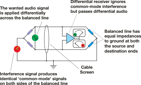
Any electromagnetic interference that makes it through the cable screen will induce identical voltages in the two signal wires. This is guaranteed because both wires have the same impedance to ground, and that's specifically what makes a 'balanced line' 'balanced'. When these identical interference voltages reach the differential amplifier (which subtracts the signal on one input from that on the other, and only passes the difference between them) at the destination they essentially cancel each other out, leaving only the wanted audio-signal voltage which is transmitted differentially between the two signal wires.
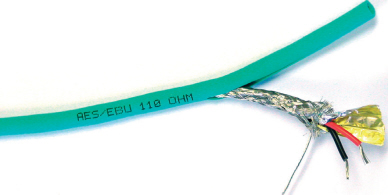
Some digital connection systems, such as coaxial S/PDIF, are not balanced. Optical S/PDIF cannot be responsible for creating ground loops as there is no signal ground in an optical cable. AES3-format digital interconnects are symmetrically balanced and should be immune to ground-loop problems.
Cable Screens
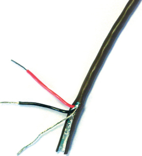
Not all screened cables are created equal – something that can become very evident when connections must be made using unbalanced cables. Even if ground loops are not responsible for inducing hum, a poorly screened cable may still allow hums and buzzes to creep into your audio. Cheap, moulded-plug cables, especially the very thin ones, often have a very loosely wrapped, spiral wire screen that still allows through a lot of interference, whereas a proper woven-screen cable is much more effective. They may seem to work OK in an area where the electrical supply is clean and there are no other sources of potential interference, but when the going gets tough, they’re simply not up to the job.
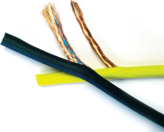
Wound and braided screens.
Braid and foil screen.
Foil screen with drain wire.

Conductive-plastic screen with drain wire.
There are different types of cable screen to suit different applications, with each offering different screening and handling attributes.
In addition to woven-screen cables, foil screened cables are also excellent at rejecting interference, although they are more often used for permanent-installation wiring. Conductive-plastic screened cables don’t work quite as well as a good woven-screen cable, but they are still perfectly adequate in most situations and have the advantage that they are very flexible, they don’t kink, and they are easy to coil, making them ideal as instrument interconnects. There is little evidence that buying really costly, esoteric cables provides any further improvement in screening – indeed, some seem to have worse screening than standard cable types – but it pays to avoid cheap cables, as both the cable itself and the connectors on either end may be less than optimal.
Unbalanced to Balanced
The simplest way of interfacing unbalanced and balanced systems, while simultaneously avoiding ground-loop problems, is to use a line transformer box. The transformer passes the signal magnetically between its separate input and output windings – which avoids any direct electrical connection and thus no ground loops – and it translates automatically between unbalanced and balanced connections too. It is important to use a unit with a transformer designed to handle line-level signals, rather than microphone-level signals, for this purpose.
However, if you have an unbalanced signal source, such as a synthesizer sound module, that you wish to connect to a balanced input, you can also avoid ground loops by taking advantage of the balanced input’s differential nature. The Sound On Sound shop sells unique and bespoke-designed high quality ‘pseudo-balanced’ interconnects, but if you are handy with a soldering iron you can make a slightly simpler version. This special cable uses standard balanced (two core plus screen) cable, with a TRS jack or XLR connector at one end wired for normal balanced operation (hot connected to pin 2/tip, cold connected to pin 3/ring, and the screen connected to pin 1 or the barrel/sleeve of the TRS plug).
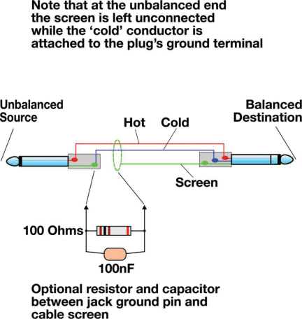
DIY ‘unbalanced source to balanced destination’ cable – the screen connects only at the destination end (or via the optional components).
At the unbalanced end don’t connect the screen to anything – cut the screen short and tape over it, if required, to ensure it stays insulated. Connect the hot wire to the tip of the unbalanced TS plug (2-pole, ‘tip and sleeve’) and the cold wire to the barrel or sleeve. The 2-pole, unbalanced plug goes into the signal source output and the balanced 3-pole TRS-jack or XLR end plugs into the balanced input you’re feeding, such as a mixer or audio interface. This arrangement transfers the audio signal perfectly, but avoids any direct ground connection and thereby avoids any possibility of a ground loop. Better interference rejection can sometimes be obtained by coupling the screen to the sleeve at the unbalanced end via a simple resistor/capacitor combination, but this is quite fiddly to achieve. The high-quality, ready-made pseudo-balanced cables available from the Sound On Sound online shop have these components built-in to maximize interference rejection, and extremely effective they are, too!
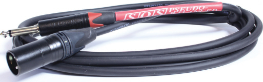
If you are not so handy with a soldering iron, you can buy high-quality, ready-made pseudo-balanced cables from the Sound On Sound website – www.soundonsound.com/shop
Gain Structure
Often we get calls for advice in situations where the user is having problems with excess noise or hiss. Most modern equipment is actually very quiet and, with the exception of guitar distortion effects, hiss shouldn’t be a problem as long as you set all your levels correctly. This all comes under the broad heading of ‘gain structure’, and the short version of the mantra here is that all signals should be adjusted so they are at the nominal working level of the equipment into which they are feeding, well above the noise floor, but never allowed to get so high as to push the device into clipping. The latter, especially, is doubly important if the receiving device is digital. The nominal working level in most professional equipment is usually about 20dB below the clipping level, and this region is called the headroom margin. Semi-professional equipment might have a more limited headroom margin of maybe as little as 12dB. The system noise floor is typically around 95dB below the nominal working level in professional equipment, and perhaps a little less in semi-pro gear.
This approach to gain structure isn’t applicable just at the input of your system – you should ensure that every piece of gear in your studio is running at its optimum signal level. If your signal level is set too low, you’ll have to make up the gain elsewhere in the system, and gain always increases the level of noise
as well as the level of wanted signal. At the same time, if the signal is too high you risk increased distortion and clipping. A lot of budget equipment can sound quite ‘hard’ and ‘strained’ when working with very high signal levels, and just optimizing the level around the nominal working level can often make a significant improvement in sound quality.
Good gain structure starts with the microphone preamplifier of your mixer, recorder or audio interface, and if you have a mixer equipped with PFL (Pre Fade Listen) buttons you can use these to check the levels of the individual inputs. Adjust the input gain trim controls until you get a sensible signal level on the meters, with the signal averaging around the 0VU mark (if analogue) or about –20dBFS on digital systems. The loudest transient peaks will typically be 8–10dB higher, although the sluggish response of an analogue VU meter probably won’t show that at all!
In situations where a separate mic preamp is being used with an audio interface that also has its own line level gain control, you should first set up the mic preamp so that its own metering shows you are in the right area, then adjust the audio interface gain to get the right meter reading in your audio software, leaving 12 to 18dB of headroom if recording at 24-bit resolution. If you have a system with outboard equipment such as reverb units connected via analogue cables, ensure that you are also sending them sensible levels so you don’t have to crank their input controls too near the top or the bottom of their range to get their meters reading correctly.
Life is somewhat easier if you are using an audio interface with its own mic preamps, connected to a computer running DAW software – here, you only need to adjust the mic amp gains until the DAW level meters show the correct level, again leaving a suitable amount of headroom as a safety margin. Distortion caused by clipping can’t be undone without recourse to extremely costly restoration software, so is to be avoided at all costs.
Bear in mind that digital metering systems show the entire headroom margin all the way up to the clipping point (0dBFS). No analogue meter has ever done this – a VU meter typically stops at +3dB, and ignores the 17dB of headroom above it! Just because the digital meter shows that headroom margin, we are not obliged to use it – it is actually there as a safety margin to cope with unexpected loud transient peaks, the same as it was for analogue systems. It can sometimes look a bit strange to have all that ‘empty space’ above the digital meters, but there is nothing wrong with tracking and mixing with the average level around –20dBFS. In fact, that is exactly the right way to be working, and your analogue monitoring chain and outboard gear will thank you for it because they are all expecting to work with a 20dB headroom margin!
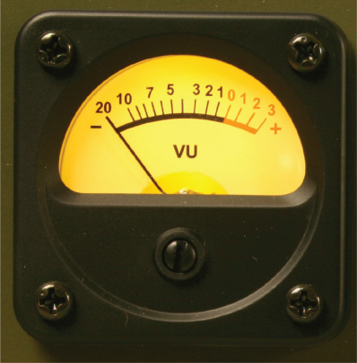
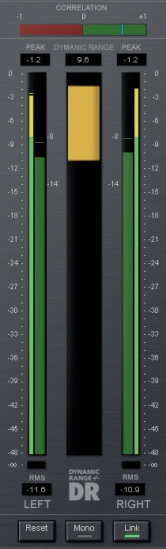
The metering in an analogue system generally shows only the normal operating level, with perhaps 20dB of safety headroom still available above this, whereas a digital system meter will show the entire range up to the point where clipping will occur.
Fully mastered material no longer requires a headroom safety margin because the peak levels are known, and so it has become standard practice to set peak levels of mastered material close to, or even at 0dBFS – but that doesn’t negate the need for it when tracking and mixing.
Impedance
Impedance is essentially a circuit’s ‘resistance’ to an alternating current (AC), but unlike resistance where a 100 ohm resistor still looks like 100 ohms whether the applied signal is 20Hz or 20kHz, impedance varies with the frequency of the applied AC signal. Of course, an audio signal is a perfect example of an AC signal that varies in frequency.
The higher the resistance in a circuit, the more voltage you need to create a given current flow through it, as dictated by Ohm’s Law, which you may (or may not) remember learning at school. Using the simple Ohm’s Law formula: V = IxR, you can always calculate the resistance, current or voltage in a circuit provided that you have the other two values (and don’t mind a little algebraic rearrangement!). If you haven’t encountered this before, R is obviously resistance (in ohms), V is the applied voltage and I is the current (in amps)
In a purely resistive circuit, resistance and impedance are the same, but in the real world circuits also have capacitance and inductance that impede the flow of current to a different extent at different frequencies. Don’t panic! We’re not going to introduce any more maths, but it is just worth knowing, at a conceptual level, that the impedance of a capacitor gets lower as the frequency increases, while the impedance of an inductor gets greater as the frequency increases. That’s why these two particular components are so useful in constructing EQ circuits, and for dealing with unwanted external interference in audio amplifiers.
Most audio equipment is designed so as to keep the input and output impedances as constant as possible over the audio range. Loudspeakers, however, are a special case, as their impedance varies quite considerably with frequency.
TIP : While you can split a signal to feed two or more destinations, provided that the combined load impedance isn’t too low to be driven by the source, you can’t just combine audio signals by simply joining outputs directly together. If you did this, each output stage will try to feed current into the others, resulting in distortion and possible equipment failure. We’ve come across instances where people have tried to do this as a means of mixing line level signals and in most cases, while nothing actually broke, the audio quality suffered significantly.
The term ‘input impedance’ equates to the electrical load that the circuit presents to any source connecting with it – somewhat counter-intuitively, the lower the input impedance, the more difficult a load it presents because it takes more current to drive it. Output impedance is related to how much current an output can supply, and the lower the output impedance of a piece of gear, the more current it can supply – so the happier it will be feeding into a low-impedance input stage. Maximum power is transferred when the output impedance of the source is equal to the input impedance of the receiving device, and this is important in power amplifiers and loudspeakers. This ‘constant impedance’ or ‘matched impedance’ arrangement is also important for digital interfaces because at the very high frequencies involved cables behave slightly strangely, and constant impedance interfaces minimize internal signal reflections.
However, in the case of analogue microphone, instrument, and line connections we’re not concerned with power and only care about the transferred signal voltage. Most of the time we simply want to get a signal out of one piece of equipment and into another without degrading it and the best way to do this is to ensure that the receiving device doesn’t place too great a load on the sending device. Consequently, standard practice is for the source impedance (the output impedance of the equipment sending the signal) to be arranged to be between five and ten times lower than the input impedance of the device receiving the signal.
For example, a mixing console has a typical microphone input impedance of between 1,500 and 2,500 ohms, and the mic you might be connecting to it will usually have an output impedance in the region of 150 to 200 ohms. Line inputs have a typical impedance of 50,000 ohms, while line output stages often have an output impedance of 100 ohms or less. An additional benefit of this loosely adopted standard is that one output can often be split to feed several inputs at the same time, without any significant reduction in signal level.
TIP : Most recording equipment operating at line level is designed to interconnect without matching problems, so in the normal course of events you won’t need to worry about impedance matching. Just plug in the correct cable and you’re in business.
On the Level
There are two ‘standard’ analogue operating levels in common usage: the –10dBV standard for semi-pro and domestic recording equipment, and the +4dBu standard for pro studio gear. The capital ‘V’ and lower case ‘u’ define different signal level references (1 volt and 0.775V rms, respectively, if you’re interested), and if we convert these levels to proper AC voltages, –10dBV is 0.316V while +4dBu is 1.228V. In other words, the nominal semi-pro signal level is about a quarter of the pro signal level. In decibel terms, the +4dBu signal is roughly 12dB louder than the –10dBV signal, but the reality is that these are close enough to each other that, so long as you set your gain controls correctly, the two standards can usually be made to work together without much problem – most equipment has enough adjustable gain range to handle either. In theory, connecting professional to semi-pro equipment or vice versa will compromise your gain structure slightly – in particular feeding a pro signal into a semi-pro device will eat well into the headroom margin. Going the other way will compromise the noise floor slightly, but with well-designed equipment the deterioration in signal-to-noise ratio is insignificant. However, where equipment offers both –10dBV and +4dBu interfacing options you should ideally use whichever is most suitable for feeding the next device in the signal chain, even if it means obtaining new cables.
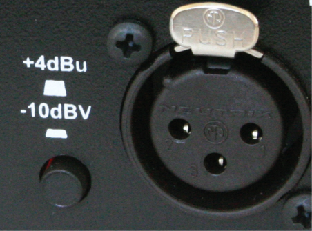
The two ‘standard’ analogue operating levels: –10dBV for semi-pro and domestic equipment, and +4dBu for pro gear. The nominal semi-pro signal level is about a quarter of the pro signal level, but so long as you set your gain controls correctly, the two standards can usually be made to work together.
Passive speakers should be connected to their power amplifiers using good-quality, low-resistance cables, with both speaker cables being the same length and as short as is practical. We’ve never found any conclusive differences in using expensive, exotic cables, but we have come across situations where the speaker cable used has been thin, lighting flex. This puts a significant resistance in series with the speaker, which will reduce the ‘damping factor’ of the system resulting in a less tight bass sound. Heavy-duty, twin-conductor mains cable, as used for garden lawnmowers, gives excellent results for the price.
For active speakers the signal is passed via ordinary line-level signal cables. Using balanced connections is beneficial where possible to minimize the risks of ground loop hums. Of course, active speakers also need mains power and there may be some benefit in buying heavy duty mains cables, as the ones supplied with equipment sometimes use thin cable, attached to the connectors at either end using crimps, rather than soldered or welded joints. A poor cable will form a resistive ‘bottleneck’ between your studio mains wiring and the equipment to which it is connected, so at the very least buy or make up a mains leads using high-current cable. The jury is still out over whether the more costly boutique mains cables can offer any significant benefit, although there’s no doubt that they offer a low-resistance path, and may also have a filtering effect on high-frequency interference.
Using good-quality, low-resistance mains leads with high-current capacity is quite sufficient in any normal recording application, in our opinion, despite the great claims made for certain boutique cable designs.
Cleaning
Connectors are made from metal and, with the exception of pure gold, they tend to corrode with age and with exposure to airborne pollutants – even gold can suffer from a build-up of contaminants. Corrosion and contamination can cause audible crackles, distortion and even brief dropouts. A specialised contact cleaner spray that does not leave a greasy residue should be applied directly to problem connectors, such as those in patchbays, XLRs or guitar jacks. This also works on mains plug pins where the ground pin, in particular, needs to be kept as clean as possible to ensure good conductivity. For cleaning jack plugs, the cleaner can be applied to a cloth for wiping the plugs or may again be sprayed directly on to the surface. In many cases, cleaning away the dirt and oxidisation results in a cleanersounding audio signal, and it certainly improves reliability.

The metal contacts in connectors can corrode with age and with exposure to pollutants – to date we have found no better troubleshooting contactcleaner product than Caig Deoxit D5.
Summary
In most cases, a studio installation will perform at its best when all the necessary mains power connections are fed from the same ring main and from sockets that are physically close together. Using power distribution strips to fan out the mains supply from a single socket or a double socket is usually fine, as project studio equipment draws relatively little current. If possible, you should avoid using the same ring main that feeds your central-heating boiler, refrigerator, or any other heavy-grade electrical equipment, as these can result in audible mains contamination.
Where everything in your system uses ‘double-insulated’ mains connections (which have no ground connection), such as laptop power supplies, small portable recorders, guitar preamps and so on, you may need to create a dedicated system ground by connecting the screen of one of your cables (or the metalwork of the associated unit) to a properly grounded point using one of the methods described earlier in this chapter. If any one piece of equipment in your system is grounded, then interference problem should not arise.
If possible, use balanced audio interconnects and use either transformer line-isolating boxes or our unbalanced-tobalanced cabling solution when feeding unbalanced sources into balanced destinations. Use good quality screened cable, especially for longer cable runs, but keep all signal cables as short as is practical and don’t run them alongside mains cables. Some basic soldering experience is always useful, as it allows you to make or modify cables to the correct lengths. Clean your connectors, including mains plug pins, every now and again to remove the grease and oxide that invariably builds up on them.