
14. Transforming Objects
Illustrator transformation tools and options provide endless possibilities to transform simple elements into visually rich artwork.
Using Liquify Tools to Reshape Objects
The liquify group of tools (Figure 14.1) provides preset distortion options, allowing you to easily add distortions, such as wrinkles and twirls, to elements.

FIGURE 14.1 Liquify tools located under the Width tool in the Essentials Classic toolbar
Tip
Selecting objects isolates them for the liquify actions. If no object is selected, liquify actions will be applied to all unlocked elements within the cursor boundary.
Use the Warp tool to mold object paths
With the Warp tool active, do the following (Figure 14.2):
Click+drag over the portion of the artwork in the direction you want to warp.

FIGURE 14.2 Warping a star shape
Customize the Warp tool
Double-click the Warp tool to open the Warp Tool Options dialog box, and then do any of the following (Figure 14.3):
Modify the size of the cursor by changing the Width and Height settings.
Modify the orientation of an asymmetric cursor by changing the Angle.
Specify how quickly the warp is applied by adjusting the Intensity. The lower the value, the slower the change occurs.
Specify the spacing between the added warp action points by adjusting the Detail. The lower the value, the greater the distance.
Specify how much to reduce the amount of unneeded action points by adjusting the Simplify values.

FIGURE 14.3 The Warp Tool Options dialog box
Use the Twirl tool to add swirls to objects
With the Twirl tool active, do the following (Figure 14.4):
Click+drag over the portion of the artwork you to which want to add a swirl.

FIGURE 14.4 Swirling a star shape
Tip
The slower you drag over the artwork, the more pronounced the tool applies the twirl.
Customize the Twirl tool
Double-click the Twirl tool to open the Twirl Tool Options dialog box, and then do any of the following (Figure 14.5):
Modify the size of the cursor by changing the Width and Height settings.
Modify the orientation of an asymmetric cursor by changing the Angle.
Specify how quickly the twirl is applied by adjusting the Intensity. The lower the value, the slower the change occurs.
Determine rotation and rate of the twirl by adjusting the Twirl Rate. Positive values twirl clockwise and negative values counterclockwise. The closer to zero, the slower the twirl is applied.
Specify the spacing between twirl action points by adjusting the Detail. The lower the value, the greater the distance.
Specify how much to reduce the amount of unneeded action points by adjusting the Simplify values.

FIGURE 14.5 The Twirl Tool Options dialog box
Use the Pucker tool to distort an object’s appearance
With the Pucker tool active, do the following (Figure 14.6):
Click or click+drag over the portion of the artwork you want to distort.

FIGURE 14.6 Clicking a star shape segment to deflate it
Customize the Pucker tool
Double-click the Pucker tool to open the Pucker Tool Options dialog box, and then do any of the following (Figure 14.7):
Modify the size of the cursor by changing the Width and Height settings.
Modify the orientation of an asymmetric cursor by changing the Angle.
Specify how quickly the pucker is applied when dragging by adjusting the Intensity. The lower the value, the slower the change occurs.
Specify the spacing between pucker action points by adjusting the Detail. The lower the value, the greater the distance.
Specify how much to reduce the amount of unneeded action points by adjusting the Simplify values.

FIGURE 14.7 The Pucker Tool Options dialog box
Use the Bloat tool to distort an object’s appearance
With the Bloat tool active, do the following (Figure 14.8):
Click or click+drag over the portion of the artwork you want to distort.

FIGURE 14.8 Clicking a star shape segment to inflate it
Customize the Bloat tool
Double-click the Bloat tool to open the Bloat Tool Options dialog box, and then do any of the following (Figure 14.9):
Modify the size of the cursor by changing the Width and Height settings.
Modify the orientation of the cursor by changing the Angle.
Specify how quickly the bloat is applied when dragging by adjusting the Intensity. The lower the value, the slower the change occurs.
Specify the spacing between bloat action points by adjusting the Detail. The lower the value, the greater the distance.
Specify how much to reduce the amount of unneeded action points by adjusting Simplify values.

FIGURE 14.9 The Bloat Tool Options dialog box
Use the Scallop tool to add random curved details to an object
With the Scallop tool active, do the following (Figure 14.10):
Click or click+drag over the portion of the artwork in the direction you want to add random curves.

FIGURE 14.10 Click+dragging with the Scallop tool around an object to add random curved details to the edges
Customize the Scallop tool
Double-click the Scallop tool to open the Scallop Tool Options dialog box, and then do any of the following (Figure 14.11):
Modify the size of the cursor by changing the Width and Height settings.
Modify the orientation of an asymmetric cursor by changing the Angle.
Specify how quickly the scallop is applied when dragging by adjusting the Intensity. The lower the value, the slower the change occurs.
Modify how near the scallops are placed in relation to the object’s outline by adjusting the Complexity.
Specify the spacing between scallop action points by adjusting the Detail. The lower the value, the greater the distance.
Enable or disable Brush Affects Anchor Points, Brush Affects In Tangent Handles, or Brush Affects Out Tangent Handles to allow the tool to change these properties.

FIGURE 14.11 The Scallop Tool Options dialog box
Use the Crystallize tool to add random spiked details to an object
With the Crystallize tool active, do the following (Figure 14.12):
Click or click+drag over the portion of the artwork in the direction you want to add random spikes.

FIGURE 14.12 Click+dragging with the Crystallize tool around an object to add random spiked details to the edges
Customize the Crystallize tool
Double-click the Crystallize tool to open the Crystallize Tool Options dialog box, and then do any of the following (Figure 14.13):
Modify the size of the cursor by changing the Width and Height settings.
Modify the orientation of an asymmetric cursor by changing the Angle.
Specify how quickly the crystallization is applied when dragging by adjusting the Intensity. The lower the value, the slower the change occurs.
Modify how near the spikes are placed in relation to the object’s outline by adjusting the Complexity.
Specify the spacing between crystallize action points by adjusting the Detail. The lower the value, the greater the distance.
Enable or disable Brush Affects Anchor Points, Brush Affects In Tangent Handles, or Brush Affects Out Tangent Handles to allow the tool to change these properties.

FIGURE 14.13 The Crystallize Tool Options dialog box
Use the Wrinkle tool to add random wavy details to an object
With the Wrinkle tool active, do the following (Figure 14.14):
Click or click+drag over the portion of the artwork in the direction you want to add random waves.

FIGURE 14.14 Click+dragging with the Wrinkle tool around an object to add random wavy details to the edges
Customize the Wrinkle tool
Double-click the Wrinkle tool to open the Wrinkle Tool Options dialog box, and then do any of the following (Figure 14.15):
Modify the size of the cursor by changing the Width and Height settings.
Modify the orientation of an asymmetric cursor by changing the Angle.
Specify how quickly the wrinkle is applied when dragging by adjusting the Intensity. The lower the value, the slower the change occurs.
Modify the distance percentage for how far the Horizontal and Vertical control point distances are.
Modify how near the action results are in relation to the object’s outline by adjusting the Complexity.
Specify the spacing between wrinkle action points by adjusting the Detail. The lower the value, the greater the distance.
Enable or disable Brush Affects Anchor Points, Brush Affects In Tangent Handles, or Brush Affects Out Tangent Handles to allow the tool to change these properties.

FIGURE 14.15 The Wrinkle Tool Options dialog box
Tip
Selecting objects before applying Blend tool actions makes it easier to see their anchor points.
Blending Objects
The Blend tool (Figure 14.16) and menu commands let you use two objects to create smooth color fills between them, evenly create and distribute new shapes between the two objects.

FIGURE 14.16 The Blend tool in the Essentials Classic toolbar
Use the Blend tool to create a blended fill visual between two objects
With the Blend tool active, do either of the following:
Click each object (not their anchor points) to sequentially blend them with no rotation (Figure 14.17).
Click an anchor point for each object to blend them using those points as reference (Figure 14.18).

FIGURE 14.17 Clicking objects to create a blended fill appearance

FIGURE 14.18 Clicking object anchor points for two open path objects to create a blended fill appearance
Tip
The Blend tool cursor changes from a white square to a black square when it is over an anchor point.
Use the Blend command to create a blended fill visual between two objects
With the two objects selected, do the following:
Choose Object > Blend > Make.
Release blended objects
With the blended objects selected, do the following:
Choose Object > Blend > Release.
Expand blended objects
With the blended objects selected, do the following:
Choose Object > Blend > Expand.
Access the Blend Options dialog box
Do any of the following:
Double-click the Blend tool.
Choose Object > Blend > Blend Options.
With blended objects selected, click the Blend Options button under Quick Actions in the Properties panel (Figure 14.19).

FIGURE 14.19 Accessing the Blend Options dialog box from the Properties panel with blended objects selected
Customize Blend options
In the Blend Options dialog box, do any of the following:
Under Spacing, choose Smooth Color to let Illustrator automatically calculate and apply the number of steps for a smoothly blended fill or stroke.
Under Spacing, choose Specified Steps and enter an appropriate number to determine the number of blended objects between the two original ones (Figure 14.20).
Under Spacing, choose Specified Distance and enter an appropriate number to specify the distance from the edge of one object and the corresponding edge of the next.
Under Orientation, choose Align to Page to set the blending action perpendicular to the page’s x-axis.
Under Orientation, choose Align to Path to set the blending action perpendicular to the blend’s spine.

FIGURE 14.20 Creating distributed shapes using the Specified Steps option
Tip
The path that the blended objects are aligned along is called the spine.
Adjust blended objects spine
With the blended objects deselected, do the following (Figure 14.21):
Using the Direct Selection tool, click to select a spine anchor point.
Drag the spine anchor point to the needed location.

FIGURE 14.21 Adjusting a spine anchor point
Replace the spine with a different path
Do the following (Figure 14.22):
Select the object to use for the new spine and the blended objects.
Choose Object > Blend > Replace Spine.

FIGURE 14.22 Replacing a spine
Tip
Spines should always be open paths to prevent unexpected results.
Reverse the blend along the spine
With the blended objects selected, do the following (Figure 14.23):
Choose Object > Blend > Reverse Spine.

FIGURE 14.23 Reversing the blend along the spine
Reverse the blended object stacking order
With the blended objects selected, do the following (Figure 14.24):
Choose Object > Blend > Reverse Front To Back.

FIGURE 14.24 Reversing the blended object stacking order
![]() VIDEO 14.1
VIDEO 14.1
Working with liquify tools and blending objects
Masking Artwork
In Illustrator, clipping masks are vector shapes that hide the artwork beyond their boundaries. The object that is used for the mask is called the clipping path. Once created, the clipping mask and related artwork it hides are called a clipping set.
Create a clipping mask to hide parts of layers or groups
When you want to hide multiple objects, it is best to use the Layers panel.
Do the following (Figure 14.26):
In the Layers panel, organize the objects to mask within the same layer.
Create the vector object to use at the clipping path and place it at the top of the layer.
With the layer highlighted in the Layers panel, click the Make/Release Clipping Mask button at the bottom of the panel.

FIGURE 14.25 Creating a clipping mask for an image object

FIGURE 14.26 Creating a clipping mask for multiple objects using the Layers panel
Tip
You can also use the Layers panel to mask individual objects.
Create a clipping mask to hide part of an object using commands
To mask individual objects, do the following (Figure 14.25):
Create the vector object to use as the clipping path and position it over the object you want to mask.
Select the object to be masked and the clipping path object.
Choose Object > Clipping Mask > Make.
Tip
To learn more about placing image files in Illustrator, see Chapter 17, “Importing Assets.”
Modify a clipping mask using commands
With the clipping set selected, do the following:
Choose Object > Clipping Mask > Edit Mask.
Apply a stroke or fill, or use the Direct Selection tool to modify the mask (Figure 14.27).

FIGURE 14.27 Adding a stroke to a mask and modifying its shape
Tip
You can also modify the mask’s fill or stroke by selecting it using the Direct Selection tool.
Modify a clipping set using the Layers panel
In the Layers panel, do any of the following:
Select an object or path, and use the Selection or Direction Selection tools to modify it (Figure 14.28).
Add or remove objects by dragging them into or out of the layer (Figure 14.29).

FIGURE 14.28 Selecting and modifying a clipping set object

FIGURE 14.29 Removing an object from a clipping set and placing it in the layer above it
Applying Transparency and Blending Modes
Transparency and opacity modifications can be applied using a number of options.
Modify opacity settings
With the objects, layers, or groups selected, do the following (Figure 14.30):
In the Opacity section of the Properties, Control, Appearance, or Transparency panel, enter a new value or adjust the value using the slider.

FIGURE 14.30 Reducing a selected object’s opacity
Access the Transparency panel
The Transparency panel (Figure 14.31) provides several options for setting opacity, applying blending modes, and creating opacity masks.
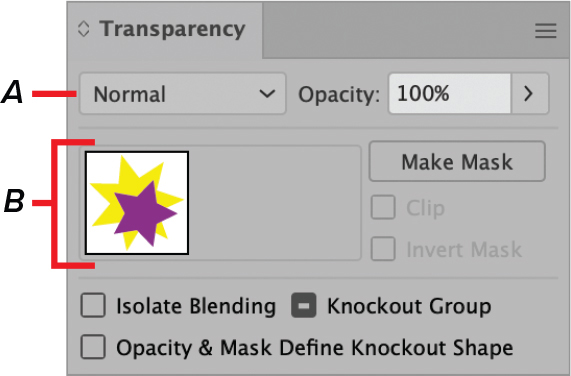
FIGURE 14.31
A. Blending Mode menu B. Opacity Mask section
To access the panel, do either of the following:
Click the word Opacity in the Properties, Control, or Appearance panel.
Choose Window > Transparency.
In the Essentials Classic workspace, click the Transparency panel thumbnail (Figure 14.32).

FIGURE 14.32 Clicking the Transparency panel thumbnail
Apply a blending mode to objects
With the objects for blending selected, do the following:
In the Transparency panel, choose an option from the Blending Mode menu (A in Figure 14.31).
Create an opacity mask
Opacity masks use images or grayscale objects to apply masks with varying degrees of transparency. Black is trans-parent, and white is opaque.
Tip
If you want to use multiple objects as a mask, group them.
Do the following:
Place the object or image to be used for the mask on top of the artwork you want to include (Figure 14.34).
Select all the elements to be included, including the opacity masking object.
In the Transparency panel, click Make Mask (Figure 14.35).
(Optional) Deselect Clip to show the artwork outside the mask boundaries and/or select Invert Mask to reverse the mask values (Figure 14.36):

FIGURE 14.34 Placing a gradient-filled object over artwork to be masked

FIGURE 14.35 Creating an opacity mask for selected objects

FIGURE 14.36 Deselecting Clip and then selecting Invert Mask
Undo an opacity mask
Do the following:
With opacity mask group selected, click Release in the Transparency panel.
Tip
Applying an opacity mask automatically groups all the objects.
![]() VIDEO 14.2
VIDEO 14.2
Working with masks and transparency
Applying Gradients
The Gradient tool and panel options (Figure 14.37) let you add gradual blends between colors to fills and stokes. You can choose gradient presets provided with Illustrator or create one of your own.

FIGURE 14.37 Applying a radial gradient fill to an object
Tip
If a document’s gradient panel has been modified, the provided preset gradient swatches may have been removed. However, you can always access them from a new blank document or using the libraries.
Apply a preset gradient to an object
With the object selected, do the following (Figure 14.38):
Make sure that either the fill or stroke color box is active, depending on which one you want to apply the gradient to.
In the Swatches panel (Window > Swatches), click the gradient swatch.

FIGURE 14.38 Applying a gradient to an object using the Swatches panel
Tip
The Gradient panel is also accessible in the Control and Properties panels when the selected object contains a gradient or when the gradient tool is active.
Change the type of gradient applied
Under Type in the Gradient panel, choose any of the following (Figure 14.39):
Linear blends the colors in a straight line.
Radial blends the colors in a circular pattern.
Freeform blends the colors within the object using paths and points positioned freely inside the object.

FIGURE 14.39 Changing an object’s gradient type from Linear to Radial
Tip
The gradient annotator can be hidden or shown by choosing View > [Show/Hide] Gradient Annotator.
Activate the Gradient Annotator
With the gradient object selected, do either of the following:
Click the Gradient tool.
In the Gradient panel, click Edit Gradient (Figure 14.40).

FIGURE 14.40 Activating editing options for a radial gradient
Tip
The Gradient Annotator does not appear with gradient strokes.
Tip
Clicking the Edit Gradient button in the Gradient panel automatically activates the Gradient tool.
Tip
In editing mode, a Gradient Annotator slider is visible for linear and radial gradients and mirrors the midpoints and color stops in the Gradient panel.
Modify a linear or radial gradient position and angle using the Gradient tool
With the gradient object selected and the Gradient tool active, do the following (Figure 14.41):
Click+drag to set the new beginning and ending points.

FIGURE 14.41 Repositioning a gradient using the Gradient tool
Modify a linear or radial gradient using the Gradient panel
In the Gradient panel (Figure 14.42), do any of the following (Figure 14:43):
Choose a different gradient from the Active Gradient menu.
Reverse the direction of the gradient by clicking the Reverse Gradient button.
Click+drag to reposition the Midpoint icons.
Click+drag to reposition the Color Stop icons.
Add a color stop by clicking a position along the bottom of the Gradient Annotation bar.
Delete a color stop by click+dragging it away from the Gradient Annotator bar, pressing Delete, or clicking the Delete Stop button.
Change the active color of a color stop by either clicking the Color Picker button to choose a color or double-clicking the color stop.
Adjust the Opacity of a color stop.
Adjust the Location of a color stop.

FIGURE 14.42
A. Active gradient B. Selected Stop color C. Reverse Gradient button D. Midpoint icon E. Gradient Annotator bar F. Color Stop icon G. Color Picker button H. Angle field I. Aspect Ratio field J. Delete Stop button K. Active Color Stop icon

FIGURE 14.43 Before and after applying the gradient edits in Figure 14.40
Tip
The Gradient Annotator does not need to be active to make adjustments to selected gradient objects using the Gradient panel.
Customize a freeform gradient using points
With a freeform gradient applied to the object and Points active in the Gradient panel, do any of the following:
Modify a color stop using the Gradient panel (Figure 14.44).
Add a color stop by clicking inside the object.
Delete a color stop by selecting it and pressing Delete or clicking the Delete Stop button.

FIGURE 14.44 Adjusting a freeform gradient color stop point
Customize a freeform gradient using lines
With a freeform gradient applied to the object and Lines active in the Gradient panel, do any of the following:
Add connected color stops by selecting a color stop and then clicking inside the object (Figure 14.45).
Modify a color stop color and options settings using the Gradient panel (Figure 14.46).
Delete a color stop by selecting it and pressing Delete or clicking the Delete Stop button.

FIGURE 14.45 Connecting a freeform gradient using lines

FIGURE 14.46 Modifying a freeform gradient line point
Tip
Freeform gradient lines cannot overlap themselves.
Apply a new gradient
With the object selected, do the following (Figure 14.47):
Select the Gradient tool.
In either the Gradient panel or the Gradient section of the Control or Properties panel, click the gradient Type you want to apply.
(Optional) Modify the gradient, as needed.

FIGURE 14.47 Applying a new gradient to an object
Tip
The attributes of the new gradient depend on the active gradient settings.
Tip
Freeform gradients can be saved as graphic styles. To learn more, see Chapter 15, “Adding Visual Effects.
Tip
To learn more about saving swatches, see “Using the Swatches Panel” in Chapter 4, “Working with Color.”
Save a linear or radial gradient
With the gradient object selected, do the following (Figure 14.48):
In the Swatches panel, either click the New Swatch button or select New Swatch from the panel menu.
In the New Swatch dialog box, enter a name for the swatch, and then click OK.

FIGURE 14.48 A new gradient saved as a swatch
Tip
Linear and radial gradients can also be saved to the Swatches panel using the Gradient panel menu.
Apply gradients to strokes
With the object selected, do the following (Figure 14.49):
Make sure the stroke color box is active.
Choose a gradient from the Gradient or Swatches panel.
Select either Linear or Radial for the gradient Type.
Select a style next to the word Stroke (Figure 14.50).

FIGURE 14.49 Applying a gradient to a stroke

FIGURE 14.50 Gradient stroke styles
![]() VIDEO 14.3
VIDEO 14.3
Working with gradients
Expanding a Live Paint group
Expanding a Live Paint group flattens the faces and edges while retaining the visual similarities of the Live Paint group.
With the group selected, do the following:
Choose Object > Live Paint > Expand.
Release a Live Paint group
Releasing removes the Live Paint group and reverts to paths with no fill and a half-point black stroke.
With the group selected, do the following:
Choose Object > Live Paint > Release.
Working with Live Paint
Live Paint tools (Figure 14.51) and commands let you create Live Paint groups from vector artwork to which you can add color, gradients, and patterns. Live Paint groups retain most of the vector drawing and editing capabilities, but treat all the paths as if they are on the same flat level of the surface.

FIGURE 14.51 Live Paint tools located under the Shape Builder tool in the Essentials Classic toolbar
Rather than strokes and fills, the paintable portions of Live paint groups are called edges and faces.
Create a Live Paint group
With the vector objects selected, do either of the following (Figure 14.52):
Select the Live Paint Bucket tool and click the selection.
Choose Object > Live Paint > Make.

FIGURE 14.52 Creating a Live Paint Group from selected objects and attributes applied to the edges and faces
Prepare objects for Live Paint conversion
Some objects require additional actions prior to converting them. Do any of the following:
For objects that did not convert directly, choose Object > Expand.
For type objects, choose Type > Create Outlines.
For raster elements, choose Object > Live Trace > Make and Convert to Live Paint.
![]() VIDEO 14.4
VIDEO 14.4
Working with Live Paint
Use the Live Paint Bucket tool to apply attributes to a Live Paint edge or face
The Live Paint Bucket adds the current fill attribute to faces within Live Paint groups or the current stroke properties to edges.
With the fill or stroke attributes you want to apply chosen, do any of the following:
Click an edge or face (Figure 14.53).
Click+drag across multiple edges or faces to paint more than one at once.
Double-click an edge or face to apply the attribute to all unassigned adjacent elements.
Triple-click an edge or face to stroke or fill all elements with the same attributes.

FIGURE 14.53 Using the Live Paint Bucket tool to apply a fill to a face element
Tip
If the Swatches panel is used to select the fill (and Cursor Swatch Preview is selected in the Live Paint Bucket Options dialog box), the cursor displays three swatches, with the active swatch in the middle. To toggle through the swatches, press the Left and/or Right Arrow keys.
Customize the Live Paint Bucket or Live Paint Selection Tool options
Do the following:
Double-click the tool to open its options dialog box.
Tip
To apply fill to edges with the Live Paint Bucket tool, select the Paint Stokes in the Live Paint Bucket Options dialog box.
Use the Live Paint Selection tool to apply attributes to a Live Paint face or edge
The Live Paint Selection tool lets you choose edges and faces within Live Paint groups.
Do any of the following, and then change the stroke or fill settings (Figure 14.54):
Click a face or edge.
Click+drag a marquee around the items you want to select.
Double-click a face to select all contiguous faces that are not separated by a painted edge.
Triple-click a face or edge to select items with the same fill or stroke.
Press Shift-click or Shift-click+drag a marquee to add or remove items from the selection.

FIGURE 14.54 Using the Live Paint Selection tool to select and apply attributes
Tip
Select > Same commands also work with the Live Paint Selection tool.