
12. Graphics and Java 2D™
Objectives
In this chapter you’ll learn:
• To understand graphics contexts and graphics objects.
• To manipulate colors.
• To manipulate fonts.
• To use methods of class Graphics to draw lines, rectangles, rectangles with rounded corners, three-dimensional rectangles, ovals, arcs and polygons.
• To use methods of class Graphics2D from the Java 2D API to draw lines, rectangles, rectangles with rounded corners, ellipses, arcs and general paths.
• To specify Paint and Stroke characteristics of shapes displayed with Graphics2D.
One picture is worth ten thousand words.
—Chinese proverb
Treat nature in terms of the cylinder, the sphere, the cone, all in perspective.
—Paul Cézanne
Colors, like features, follow the changes of the emotions.
—Pablo Picasso
Nothing ever becomes real till it is experienced—even a proverb is no proverb to you till your life has illustrated it.
—John Keats
Outline
12.1 Introduction
12.2 Graphics Contexts and Graphics Objects
12.3 Color Control
12.4 Font Control
12.5 Drawing Lines, Rectangles and Ovals
12.6 Drawing Arcs
12.7 Drawing Polygons and Polylines
12.8 Java 2D API
12.9 Wrap-Up
12.1 Introduction
In this chapter, we overview several of Java’s capabilities for drawing two-dimensional shapes, controlling colors and controlling fonts. One of Java’s initial appeals was its support for graphics that enabled programmers to visually enhance their applications. Java now contains many more sophisticated drawing capabilities as part of the Java 2D™ API. This chapter begins with an introduction to many of Java’s original drawing capabilities. Next we present several of the more powerful Java 2D capabilities, such as controlling the style of lines used to draw shapes and the way shapes are filled with color and patterns.
Figure 12.1 shows a portion of the Java class hierarchy that includes several of the basic graphics classes and Java 2D API classes and interfaces covered in this chapter. Class Color contains methods and constants for manipulating colors. Class JComponent contains method paintComponent, which is used to draw graphics on a component. Class Font contains methods and constants for manipulating fonts. Class FontMetrics contains methods for obtaining font information. Class Graphics contains methods for drawing strings, lines, rectangles and other shapes. Class Graphics2D, which extends class Graphics, is used for drawing with the Java 2D API. Class Polygon contains methods for creating polygons. The bottom half of the figure lists several classes and interfaces from the Java 2D API. Class BasicStroke helps specify the drawing characteristics of lines. Classes GradientPaint and TexturePaint help specify the characteristics for filling shapes with colors or patterns. Classes GeneralPath, Line2D, Arc2D, Ellipse2D, Rectangle2D and RoundRectangle2D represent several Java 2D shapes. [Note: We begin the chapter by discussing Java’s original graphics capabilities, then move on to the Java 2D API. Now, the classes that were part of Java’s original graphics capabilities are considered to be part of the Java 2D API.]
Fig. 12.1. Classes and interfaces used in this chapter from Java’s original graphics capabilities and from the Java 2D API. [Note: Class Object appears here because it is the superclass of the Java class hierarchy. Also, abstract classes appear in italics.]

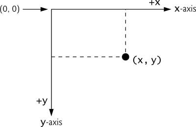
To begin drawing in Java, we must first understand Java’s coordinate system (Fig. 12.2), which is a scheme for identifying every point on the screen. By default, the upper-left corner of a GUI component (e.g., a window) has the coordinates (0, 0). A coordinate pair is composed of an x-coordinate (the horizontal coordinate) and a y-coordinate (the vertical coordinate). The x-coordinate is the horizontal distance moving right from the left of the screen. The y-coordinate is the vertical distance moving down from the top of the screen. The x-axis describes every horizontal coordinate, and the y-axis every vertical coordinate. The coordinates are used to indicate where graphics should be displayed on a screen. Coordinate units are measured in pixels (which stands for “picture element”). A pixel is a display monitor’s smallest unit of resolution.
Fig. 12.2. Java coordinate system. Units are measured in pixels.
Portability Tip 12.1
![]()
Different display monitors have different resolutions (i.e., the density of the pixels varies). This can cause graphics to appear in different sizes on different monitors or on the same monitor with different settings.
12.2 Graphics Contexts and Graphics Objects
A graphics context enables drawing on the screen. A Graphics object manages a graphics context and draws pixels on the screen that represent text and other graphical objects (e.g., lines, ellipses, rectangles and other polygons). Graphics objects contain methods for drawing, font manipulation, color manipulation and the like.
Class Graphics is an abstract class (i.e., Graphics objects cannot be instantiated). This contributes to Java’s portability. Because drawing is performed differently on every platform that supports Java, there cannot be only one implementation of the drawing capabilities across all systems. For example, the graphics capabilities that enable a PC running Microsoft Windows to draw a rectangle are different from those that enable a Linux workstation to draw a rectangle—and they are both different from the graphics capabilities that enable a Macintosh to draw a rectangle. When Java is implemented on each platform, a subclass of Graphics is created that implements the drawing capabilities. This implementation is hidden by class Graphics, which supplies the interface that enables us to use graphics in a platform-independent manner.
Class Component is the superclass for many of the classes in the java.awt package. (We introduced class Component in Chapter 11.) Class JComponent, which inherits indirectly from class Component, contains a paintComponent method that can be used to draw graphics. Method paintComponent takes a Graphics object as an argument. This object is passed to the paintComponent method by the system when a lightweight Swing component needs to be repainted. The header for the paintComponent method is
public void paintComponent( Graphics g )
Parameter g receives a reference to an instance of the system-specific subclass that Graphics extends. The preceding method header should look familiar to you—it is the same one we used in some of the applications in Chapter 11. Actually, class JComponent is a super-class of JPanel. Many capabilities of class JPanel are inherited from class JComponent.
Method paintComponent is seldom called directly by the programmer because drawing graphics is an event-driven process. When a GUI application executes, the application container calls method paintComponent for each lightweight component as the GUI is displayed. For paintComponent to be called again, an event must occur (such as covering and uncovering the component with another window).
If the programmer needs to have paintComponent execute (i.e., if the programmer wants to update the graphics drawn on the Swing component), a call is made to method repaint, which is inherited by all JComponents indirectly from class Component (package java.awt). Method repaint is frequently called to request a call to method paintComponent. The header for repaint is
public void repaint()
12.3 Color Control
Class Color declares methods and constants for manipulating colors in a Java program. The predeclared color constants are summarized in Fig. 12.3, and several color methods and constructors are summarized in Fig. 12.4. Note that two of the methods in Fig. 12.4 are Graphics methods that are specific to colors.
Fig. 12.3. Color constants and their RGB values.

Fig. 12.4. Color methods and color-related Graphics methods.
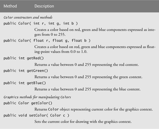
Every color is created from a red, a green and a blue component. Together these components are called RGB values. All three RGB components can be integers in the range from 0 to 255, or they can be floating-point values in the range 0.0 to 1.0. The first RGB component specifies the amount of red, the second the amount of green and the third the amount of blue. The larger the RGB value, the greater the amount of that particular color. Java enables the programmer to choose from 256 × 256 × 256 (approximately 16.7 million) colors. Not all computers are capable of displaying all these colors. The computer will display the closest color it can.
Two of class Color’s constructors are shown in Fig. 12.4—one that takes three int arguments and one that takes three float arguments, with each argument specifying the amount of red, green and blue. The int values must be in the range 0–255 and the float values must be in the range 0.0–1.0. The new Color object will have the specified amounts of red, green and blue. Color methods getRed, getGreen and getBlue return integer values from 0 to 255 representing the amount of red, green and blue, respectively. Graphics method getColor returns a Color object representing the current drawing color. Graphics method setColor sets the current drawing color.
Figures 12.5–12.6 demonstrates several methods from Fig. 12.4 by drawing filled rectangles and strings in several different colors. When the application begins execution, class ColorJPanel’s paintComponent method (lines 10–37 of Fig. 12.5) is called to paint the window. Line 17 uses Graphics method setColor to set the drawing color. Method setColor receives a Color object. The expression new Color( 255, 0, 0 ) creates a new Color object that represents red (red value 255, and 0 for the green and blue values). Line 18 uses Graphics method fillRect to draw a filled rectangle in the current color. Method fillRect draws a rectangle based on its four arguments. The first two integer values represent the upper-left x-coordinate and upper-left y-coordinate, where the Graphics object begins drawing the rectangle. The third and fourth arguments are nonnegative integers that represent the width and the height of the rectangle in pixels, respectively. A rectangle drawn using method fillRect is filled by the current color of the Graphics object.
Fig. 12.5. Color changed for drawing.
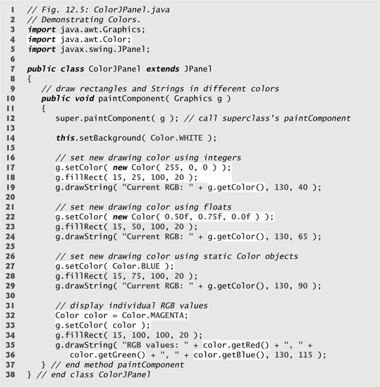
Fig. 12.6. Creating JFrame to display colors on JPanel.


Line 19 uses Graphics method drawString to draw a String in the current color. The expression g.getColor() retrieves the current color from the Graphics object. The returned Color object is concatenated with string "Current RGB: ", resulting in an implicit call to class Color’s toString method. The String representation of a Color contains the class name and package (java.awt.Color), and the red, green and blue values.
Look-and-Feel Observation 12.1
![]()
Everyone perceives colors differently. Choose your colors carefully to ensure that your application is readable, both for people who can perceive color and for people who are color blind. Try to avoid using many different colors in close proximity.
Lines 22–24 and lines 27–29 perform the same tasks again. Line 22 uses the Color constructor with three float arguments to create a dark green color (0.50f for red, 0.75f for green and 0.0f for blue). Note the syntax of the values. The letter f appended to a floating-point literal indicates that the literal should be treated as type float. Recall that by default, floating-point literals are treated as type double.
Line 27 sets the current drawing color to one of the predeclared Color constants (Color.BLUE). The Color constants are static, so they are created when class Color is loaded into memory at execution time.
The statement in lines 35–36 makes calls to Color methods getRed, getGreen and getBlue on the predeclared Color.MAGENTA constant. Method main of class ShowColors (lines 8–18 of Fig. 12.6) creates the JFrame that will contain a ColorJPanel object where the colors will be displayed.
Software Engineering Observation 12.1
![]()
To change the color, you must create a new Color object (or use one of the predeclared Color constants). Like String objects, Color objects are immutable (not modifiable).
Package javax.swing provides class JColorChooser to enable application users to select colors. Figures 12.7–12.8 demonstrate a JColorChooser dialog. When you click the Change Color button, a JColorChooser dialog appears. When you select a color and press the dialog’s OK button, the background color of the application window changes.
Fig. 12.7. JColorChooser dialog.


Fig. 12.8. Choosing colors with JColorChooser.
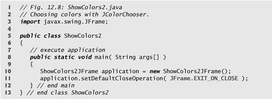
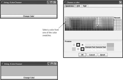
Class JColorChooser provides static method showDialog, which creates a JColorChooser object, attaches it to a dialog box and displays the dialog. Lines 36–37 of Fig. 12.7 invoke this method to display the color chooser dialog. Method showDialog returns the selected Color object, or null if the user presses Cancel or closes the dialog without pressing OK. The method takes three arguments—a reference to its parent Component, a String to display in the title bar of the dialog and the initial selected Color for the dialog. The parent component is a reference to the window from which the dialog is displayed (in this case the JFrame, with the reference name frame). The dialog will be centered on the parent. If the parent is null, the dialog is centered on the screen. While the color chooser dialog is on the screen, the user cannot interact with the parent component. This type of dialog is called a modal dialog (discussed in Chapter 17, GUI Components: Part 2).
After the user selects a color, lines 40–41 determine whether color is null, and, if so, set color to Color.LIGHT_GRAY. Line 44 invokes method setBackground to change the background color of the JPanel. Method setBackground is one of the many Component methods that can be used on most GUI components. Note that the user can continue to use the Change Color button to change the background color of the application. Figure 12.8 contains method main, which executes the program.
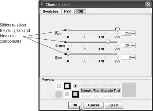
The second screen capture of Fig. 12.8 demonstrates the default JColorChooser dialog that allows the user to select a color from a variety of color swatches. Note that there are actually three tabs across the top of the dialog—Swatches, HSB and RGB. These represent three different ways to select a color. The HSB tab allows you to select a color based on hue, saturation and brightness—values that are used to define the amount of light in a color. We do not discuss HSB values. For more information on hue, saturation and brightness, visit whatis.techtarget.com/definition/0,,sid9_gci212262,00.html. The RGB tab allows you to select a color by using sliders to select the red, green and blue components. The HSB and RGB tabs are shown in Fig. 12.9.
Fig. 12.9. HSB and RGB tabs of the JColorChooser dialog.

12.4 Font Control
This section introduces methods and constants for font control. Most font methods and font constants are part of class Font. Some methods of class Font and class Graphics are summarized in Fig. 12.10.
Fig. 12.10. Font-related methods and constants.

Class Font’s constructor takes three arguments—the font name, font style and font size. The font name is any font currently supported by the system on which the program is running, such as standard Java fonts Monospaced, SansSerif and Serif. The font style is Font.PLAIN, Font.ITALIC or Font.BOLD (each is a static field of class Font). Font styles can be used in combination (e.g., Font.ITALIC + Font.BOLD). The font size is measured in points. A point is 1/72 of an inch. Graphics method setFont sets the current drawing font—the font in which text will be displayed—to its Font argument.
Portability Tip 12.2
![]()
The number of fonts varies greatly across systems. Java provides five font names—Serif, Monospaced, SansSerif, Dialog and DialogInput—that can be used on all Java platforms. The Java runtime environment (JRE) on each platform maps these logical font names to actual fonts installed on the platform. The actual fonts used may vary by platform.
The application of Figs. 12.11–12.12 displays text in four different fonts, with each font in a different size. Figure 12.11 uses the Font constructor to initialize Font objects (in lines 16, 20, 24 and 29) that are each passed to Graphics method setFont to change the drawing font. Each call to the Font constructor passes a font name (Serif, Monospaced or SansSerif) as a string, a font style (Font.PLAIN, Font.ITALIC or Font.BOLD) and a font size. Once Graphics method setFont is invoked, all text displayed following the call will appear in the new font until the font is changed. Each font’s information is displayed in lines 17, 21, 25 and 30–31 using method drawString. Note that the coordinate passed to drawString corresponds to the lower-left corner of the baseline of the font. Line 28 changes the drawing color to red, so the next string displayed appears in red. Lines 30–31 display information about the final Font object. Method getFont of class Graphics returns a Font object representing the current font. Method getName returns the current font name as a string. Method getSize returns the font size in points.
Fig. 12.11. Graphics method setFont changes the drawing font.

Fig. 12.12. Creating a JFrame to display fonts.

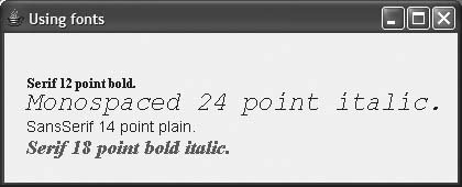
Figure 12.12 contains method main, which creates a JFrame. We add a FontJPanel object to this JFrame (line 15), which displays the graphics created in Fig. 12.11.
Software Engineering Observation 12.2
![]()
To change the font, you must create a new Font object. Font objects are immutable—class Font has no set methods to change the characteristics of the current font.
Font Metrics
Sometimes it is necessary to get information about the current drawing font, such as its name, style and size. Several Font methods used to get font information are summarized in Fig. 12.10. Method getStyle returns an integer value representing the current style. The integer value returned is either Font.PLAIN, Font.ITALIC, Font.BOLD or the combination of Font.ITALIC and Font.BOLD. Method getFamily returns the name of the font family to which the current font belongs. The name of the font family is platform specific. Font methods are also available to test the style of the current font, and these too are summarized in Fig. 12.10. Methods isPlain, isBold and isItalic return true if the current font style is plain, bold or italic, respectively.
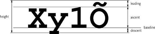
Sometimes precise information about a font’s metrics must be known—such as height, descent (the amount a character dips below the baseline), ascent (the amount a character rises above the baseline) and leading (the difference between the descent of one line of text and the ascent of the line of text below it—that is, the interline spacing). Figure 12.13 illustrates some of the common font metrics.
Fig. 12.13. Font metrics.
Class FontMetrics declares several methods for obtaining font metrics. These methods and Graphics method getFontMetrics are summarized in Fig. 12.14. The application of Figs. 12.15–12.16 uses the methods of Fig. 12.14 to obtain font metric information for two fonts.
Fig. 12.14. FontMetrics and Graphics methods for obtaining font metrics.
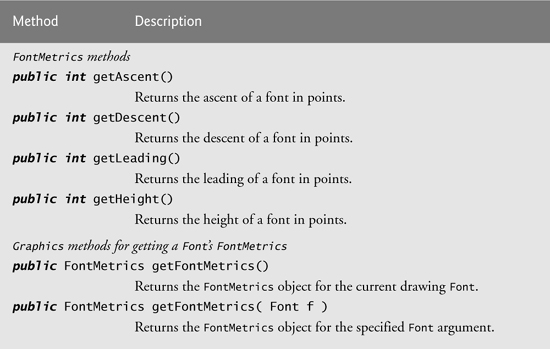
Fig. 12.15. Font metrics.
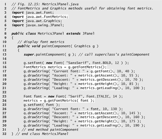
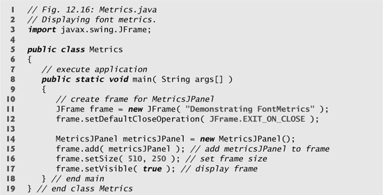
Fig. 12.16. Creating JFrame to display font metric information.

Line 15 of Fig. 12.15 creates and sets the current drawing font to a SansSerif, bold, 12-point font. Line 16 uses Graphics method getFontMetrics to obtain the FontMetrics object for the current font. Line 17 outputs the String representation of the Font returned by g.getFont(). Lines 18–21 use FontMetric methods to obtain the ascent, descent, height and leading for the font.
Line 23 creates a new Serif, italic, 14-point font. Line 24 uses a second version of Graphics method getFontMetrics, which accepts a Font argument and returns a corresponding FontMetrics object. Lines 27–30 obtain the ascent, descent, height and leading for the font. Note that the font metrics are slightly different for the two fonts.
12.5 Drawing Lines, Rectangles and Ovals
This section presents Graphics methods for drawing lines, rectangles and ovals. The methods and their parameters are summarized in Fig. 12.17. For each drawing method that requires a width and height parameter, the width and height must be nonnegative values. Otherwise, the shape will not display.
Fig. 12.17. Graphics methods that draw lines, rectangles and ovals.


The application of Figs. 12.18–12.19 demonstrates drawing a variety of lines, rectangles, three-dimensional rectangles, rounded rectangles and ovals.
Fig. 12.18. Drawing lines, rectangles and ovals.
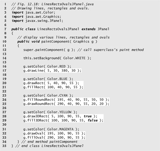
Fig. 12.19. Creating JFrame to display lines, rectangles and ovals.


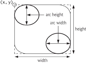
In Fig. 12.18, line 17 draws a red line, line 20 draws an empty blue rectangle and line 21 draws a filled blue rectangle. Methods fillRoundRect (line 24) and drawRoundRect (line 25) draw rectangles with rounded corners. Their first two arguments specify the coordinates of the upper-left corner of the bounding rectangle—the area in which the rounded rectangle will be drawn. Note that the upper-left corner coordinates are not the edge of the rounded rectangle, but the coordinates where the edge would be if the rectangle had square corners. The third and fourth arguments specify the width and height of the rectangle. The last two arguments determine the horizontal and vertical diameters of the arc (i.e., the arc width and arc height) used to represent the corners.
Figure 12.20 labels the arc width, arc height, width and height of a rounded rectangle. Using the same value for the arc width and arc height produces a quarter-circle at each corner. When the arc width, arc height, width and height have the same values, the result is a circle. If the values for width and height are the same and the values of arcWidth and arcHeight are 0, the result is a square.
Fig. 12.20. Arc width and arc height for rounded rectangles.
Methods draw3DRect (line 28) and fill3DRect (line 29) take the same arguments. The first two arguments specify the top-left corner of the rectangle. The next two arguments specify the width and height of the rectangle, respectively. The last argument determines whether the rectangle is raised (true) or lowered (false). The three-dimensional effect of draw3DRect appears as two edges of the rectangle in the original color and two edges in a slightly darker color. The three-dimensional effect of fill3DRect appears as two edges of the rectangle in the original drawing color and the fill and other two edges in a slightly darker color. Raised rectangles have the original drawing color edges at the top and left of the rectangle. Lowered rectangles have the original drawing color edges at the bottom and right of the rectangle. The three-dimensional effect is difficult to see in some colors.
Methods drawOval and fillOval (lines 32–33) take the same four arguments. The first two arguments specify the top-left coordinate of the bounding rectangle that contains the oval. The last two arguments specify the width and height of the bounding rectangle, respectively. Figure 12.21 shows an oval bounded by a rectangle. Note that the oval touches the center of all four sides of the bounding rectangle. (The bounding rectangle is not displayed on the screen.)
Fig. 12.21. Oval bounded by a rectangle.

12.6 Drawing Arcs
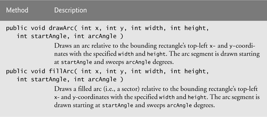
An arc is drawn as a portion of an oval. Arc angles are measured in degrees. Arcs sweep (i.e., move along a curve) from a starting angle by the number of degrees specified by their arc angle. The starting angle indicates in degrees where the arc begins. The arc angle specifies the total number of degrees through which the arc sweeps. Figure 12.22 illustrates two arcs. The left set of axes shows an arc sweeping from zero degrees to approximately 110 degrees. Arcs that sweep in a counterclockwise direction are measured in positive degrees. The set of axes on the right shows an arc sweeping from zero degrees to approximately –110 degrees. Arcs that sweep in a clockwise direction are measured in negative degrees. Note the dashed boxes around the arcs in Fig. 12.22. When drawing an arc, we specify a bounding rectangle for an oval. The arc will sweep along part of the oval. Graphics methods drawArc and fillArc for drawing arcs are summarized in Fig. 12.23.
Fig. 12.22. Positive and negative arc angles.
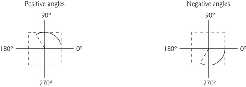
Fig. 12.23. Graphics methods for drawing arcs.
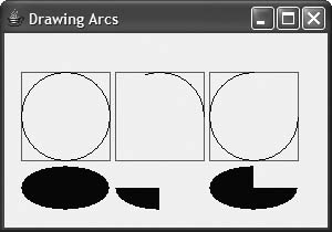
The application of Fig. 12.24–Fig. 12.25 demonstrates the arc methods of Fig. 12.23. The application draws six arcs (three unfilled and three filled). To illustrate the bounding rectangle that helps determine where the arc appears, the first three arcs are displayed inside a red rectangle that has the same x, y, width and height arguments as the arcs.
Fig. 12.24. Arcs displayed with drawArc and fillArc.

Fig. 12.25. Creating JFrame to display arcs.

12.7 Drawing Polygons and Polylines
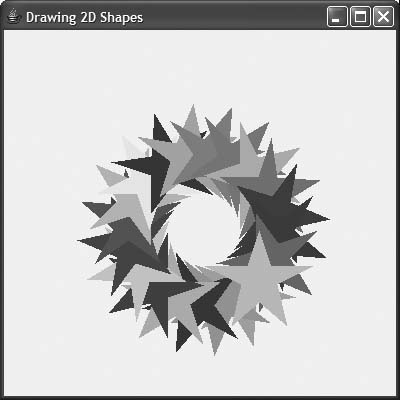
Polygons are closed multisided shapes composed of straight-line segments. Polylines are sequences of connected points. Figure 12.26 discusses methods for drawing polygons and polylines. Note that some methods require a Polygon object (package java.awt). Class Polygon’s constructors are also described in Fig. 12.26. The application of Figs. 12.27–12.28 draws polygons and polylines.
Fig. 12.26. Graphics methods for polygons and class Polygon methods.

Fig. 12.27. Polygons displayed with drawPolygon and fillPolygon.


Fig. 12.28. Creating JFrame to display polygons.

Lines 15–16 of Fig. 12.27 create two int arrays and use them to specify the points for Polygon polygon1. The Polygon constructor call in line 17 receives array xValues, which contains the x-coordinate of each point; array yValues, which contains the y-coordinate of each point and 6 (the number of points in the polygon). Line 18 displays polygon1 by passing it as an argument to Graphics method drawPolygon.
Lines 21–22 create two int arrays and use them to specify the points for a series of connected lines. Array xValues2 contains the x-coordinate of each point and array yValues2 the y-coordinate of each point. Line 23 uses Graphics method drawPolyline to display the series of connected lines specified with the arguments xValues2, yValues2 and 7 (the number of points).
Lines 26–27 create two int arrays and use them to specify the points of a polygon. Array xValues3 contains the x-coordinate of each point and array yValues3 the y-coordinate of each point. Line 28 displays a polygon by passing to Graphics method fillPolygon the two arrays (xValues3 and yValues3) and the number of points to draw (4).
![]()
An ArrayIndexOutOfBoundsException is thrown if the number of points specified in the third argument to method drawPolygon or method fillPolygon is greater than the number of elements in the arrays of coordinates that specify the polygon to display.
Line 31 of Fig. 12.27 creates Polygon polygon2 with no points. Lines 32–36 use Polygon method addPoint to add pairs of x- and y-coordinates to the Polygon. Line 37 displays Polygon polygon2 by passing it to Graphics method fillPolygon.
12.8 Java 2D API
The Java 2D API provides advanced two-dimensional graphics capabilities for programmers who require detailed and complex graphical manipulations. The API includes features for processing line art, text and images in packages java.awt, java.awt.image, java.awt.color, java.awt.font, java.awt.geom, java.awt.print and java.awt.image.renderable. The capabilities of the API are far too broad to cover in this textbook. For an overview of the capabilities, see the Java 2D demo (located in your JDK’s demojfcJava2D directory) or visit the website java.sun.com/products/java-media/2D/index.html. In this section, we overview several Java 2D capabilities.
Drawing with the Java 2D API is accomplished with a Graphics2D reference (package java.awt). Graphics2D is an abstract subclass of class Graphics, so it has all the graphics capabilities demonstrated earlier in this chapter. In fact, the actual object used to draw in every paintComponent method is an instance of a subclass of Graphics2D that is passed to method paintComponent and accessed via the superclass Graphics. To access Graphics2D capabilities, we must cast the Graphics reference (g) passed to paintComponent into a Graphics2D reference with a statement such as
Graphics2D g2d = ( Graphics2D ) g;
The next two examples use this technique.
Lines, Rectangles, Round Rectangles, Arcs and Ellipses
The next example demonstrates several Java 2D shapes from package java.awt.geom, including Line2D.Double, Rectangle2D.Double, RoundRectangle2D.Double, Arc2D.Double and Ellipse2D.Double. Note the syntax of each class name. Each of these classes represents a shape with dimensions specified as double-precision floating-point values. There is a separate version of each represented with single-precision floating-point values (e.g., Ellipse2D.Float). In each case, Double is a static nested class of the class specified to the left of the dot (e.g., Ellipse2D). To use the static nested class, we simply qualify its name with the outer class name.
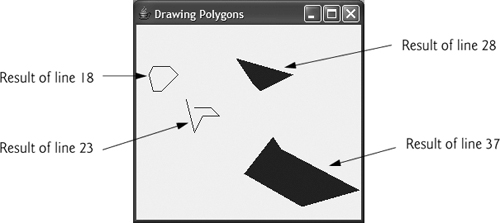
In Figs. 12.29–12.30, we draw Java 2D shapes and modify their drawing characteristics, such as changing line thickness, filling shapes with patterns and drawing dashed lines. These are just a few of the many capabilities provided by Java 2D.
Fig. 12.29. Java 2D shapes.

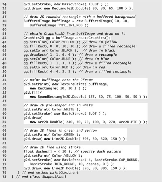
Fig. 12.30. Creating JFrame to display shapes.


Line 25 of Fig. 12.29 casts the Graphics reference received by paintComponent to a Graphics2D reference and assigns it to g2d to allow access to the Java 2D features.
Ovals, Gradient Fills and Paint Objects
The first shape we draw is an oval filled with gradually changing colors. Lines 28–29 invoke Graphics2D method setPaint to set the Paint object that determines the color for the shape to display. A Paint object implements interface java.awt.Paint. It can be something as simple as one of the predeclared Color objects introduced in Section 12.3 (class Color implements Paint), or it can be an instance of the Java 2D API’s GradientPaint, SystemColor, TexturePaint, LinearGradientPaint or RadialGradientPaint classes. In this case, we use a GradientPaint object.
Class GradientPaint helps draw a shape in gradually changing colors—called a gradient. The GradientPaint constructor used here requires seven arguments. The first two specify the starting coordinate for the gradient. The third specifies the starting Color for the gradient. The fourth and fifth specify the ending coordinate for the gradient. The sixth specifies the ending Color for the gradient. The last argument specifies whether the gradient is cyclic (true) or acyclic (false). The two sets of coordinates determine the direction of the gradient. Because the second coordinate (35, 100) is down and to the right of the first coordinate (5, 30), the gradient goes down and to the right at an angle. Because this gradient is cyclic (true), the color starts with blue, gradually becomes yellow, then gradually returns to blue. If the gradient is acyclic, the color transitions from the first color specified (e.g., blue) to the second color (e.g., yellow).
Line 30 uses Graphics2D method fill to draw a filled Shape object—an object that implements interface Shape (package java.awt). In this case, we display an Ellipse2D.Double object. The Ellipse2D.Double constructor receives four arguments specifying the bounding rectangle for the ellipse to display.
Rectangles, Strokes
Next we draw a red rectangle with a thick border. Line 33 invokes setPaint to set the Paint object to Color.RED. Line 34 uses Graphics2D method setStroke to set the characteristics of the rectangle’s border (or the lines for any other shape). Method setStroke requires as its argument an object that implements interface Stroke (package java.awt). In this case, we use an instance of class BasicStroke. Class BasicStroke provides several constructors to specify the width of the line, how the line ends (called the end caps), how lines join together (called line joins) and the dash attributes of the line (if it is a dashed line). The constructor here specifies that the line should be 10 pixels wide.
Line 35 uses Graphics2D method draw to draw a Shape object—in this case, a Rectangle2D.Double. The Rectangle2D.Double constructor receives four arguments specifying the upper-left x-coordinate, upper-left y-coordinate, width and height of the rectangle.
Rounded Rectangles, BufferedImages and TexturePaint Objects
Next we draw a rounded rectangle filled with a pattern created in a BufferedImage (package java.awt.image) object. Lines 38–39 create the BufferedImage object. Class BufferedImage can be used to produce images in color and grayscale. This particular BufferedImage is 10 pixels wide and 10 pixels tall (as specified by the first two arguments of the constructor). The third argument BufferedImage.TYPE_INT_RGB indicates that the image is stored in color using the RGB color scheme.
To create the rounded rectangle’s fill pattern, we must first draw into the BufferedImage. Line 42 creates a Graphics2D object (with a call to BufferedImage method createGraphics) that can be used to draw into the BufferedImage. Lines 43–50 use methods setColor, fillRect and drawRect (discussed earlier in this chapter) to create the pattern.
Lines 53–54 set the Paint object to a new TexturePaint (package java.awt) object. A TexturePaint object uses the image stored in its associated BufferedImage (the first constructor argument) as the fill texture for a filled-in shape. The second argument specifies the Rectangle area from the BufferedImage that will be replicated through the texture. In this case, the Rectangle is the same size as the BufferedImage. However, a smaller portion of the BufferedImage can be used.
Lines 55–56 use Graphics2D method fill to draw a filled Shape object—in this case, a RoundRectangle2D.Double. The constructor for class RoundRectangle2D.Double receives six arguments specifying the rectangle dimensions and the arc width and arc height used to determine the rounding of the corners.
Arcs
Next we draw a pie-shaped arc with a thick white line. Line 59 sets the Paint object to Color.WHITE. Line 60 sets the Stroke object to a new BasicStroke for a line 6 pixels wide. Lines 61–62 use Graphics2D method draw to draw a Shape object—in this case, an Arc2D.Double. The Arc2D.Double constructor’s first four arguments specify the upper-left x-coordinate, upper-left y-coordinate, width and height of the bounding rectangle for the arc. The fifth argument specifies the start angle. The sixth argument specifies the arc angle. The last argument specifies how the arc is closed. Constant Arc2D.PIE indicates that the arc is closed by drawing two lines—one line from the arc’s starting point to the center of the bounding rectangle and one line from the center of the bounding rectangle to the ending point. Class Arc2D provides two other static constants for specifying how the arc is closed. Constant Arc2D.CHORD draws a line from the starting point to the ending point. Constant Arc2D.OPEN specifies that the arc should not be closed.
Lines
Finally, we draw two lines using Line2D objects—one solid and one dashed. Line 65 sets the Paint object to Color.GREEN. Line 66 uses Graphics2D method draw to draw a Shape object—in this case, an instance of class Line2D.Double. The Line2D.Double constructor’s arguments specify the starting coordinates and ending coordinates of the line.
Line 69 declares a one-element float array containing the value 10. This array will be used to describe the dashes in the dashed line. In this case, each dash will be 10 pixels long. To create dashes of different lengths in a pattern, simply provide the length of each dash as an element in the array. Line 70 sets the Paint object to Color.YELLOW. Lines 71–72 set the Stroke object to a new BasicStroke. The line will be 4 pixels wide and will have rounded ends (BasicStroke.CAP_ROUND). If lines join together (as in a rectangle at the corners), their joining will be rounded (BasicStroke.JOIN_ROUND). The dashes argument specifies the dash lengths for the line. The last argument indicates the starting index in the dashes array for the first dash in the pattern. Line 73 then draws a line with the current Stroke.
Creating Your Own Shapes with General Paths
Next we present a general path—a shape constructed from straight lines and complex curves. A general path is represented with an object of class GeneralPath (package java.awt.geom). The application of Figs. 12.31 and 12.32 demonstrates drawing a general path in the shape of a five-pointed star.
Fig. 12.31. Java 2D general paths.

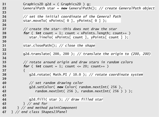
Fig. 12.32. Creating JFrame to display stars.

Lines 18–19 declare two int arrays representing the x- and y-coordinates of the points in the star. Line 22 creates GeneralPath object star. Line 25 uses GeneralPath method moveTo to specify the first point in the star. The for statement in lines 28–29 uses GeneralPath method lineTo to draw a line to the next point in the star. Each new call to lineTo draws a line from the previous point to the current point. Line 31 uses GeneralPath method closePath to draw a line from the last point to the point specified in the last call to moveTo. This completes the general path.
Line 33 uses Graphics2D method translate to move the drawing origin to location (200, 200). All drawing operations now use location (200, 200) as (0, 0).
The for statement in lines 36–45 draws the star 20 times by rotating it around the new origin point. Line 38 uses Graphics2D method rotate to rotate the next displayed shape. The argument specifies the rotation angle in radians (with 360° = 2π radians). Line 44 uses Graphics2D method fill to draw a filled version of the star.
12.9 Wrap-Up
In this chapter, you learned how to use Java’s graphics capabilities to produce colorful drawings. You learned how to specify the location of an object using Java’s coordinate system, and how to draw on a window using the paintComponent method. You were introduced to class Color, and learned how to use this class to specify different colors using their RGB components. You used the JColorChooser dialog to allow users to select colors in a program. You then learned how to work with fonts when drawing text on a window. You learned how to create a Font object from a font name, style and size, as well as how to access the metrics of a font. From there, you learned how to draw various shapes on a window, such as rectangles (regular, rounded and 3D), ovals and polygons, as well as lines and arcs. You then used the Java 2D API to create more complex shapes and to fill them with gradients or patterns. The chapter concluded with a discussion of general paths, used to construct shapes from straight lines and complex curves. In the next chapter, you’ll learn about exceptions, useful for handling errors during a program’s execution. Handling errors in this way provides for more robust programs.