
Chapter 1 Getting Started
1-1 Introduction
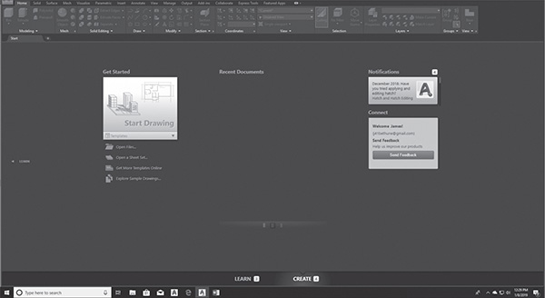
The figure on the previous page shows the initial AutoCAD drawing screen. It will appear when the program is first accessed.
To Start a New Drawing
 Click the arrowhead in the Get Started box on the Welcome screen.
A listing of available templates will appear on the Select template dialog box. See Figure 1-1. Various templates will be used throughout the text, but for a start, we will use the acad.dwt template. The acad.dwt template defines inches as its primary units.
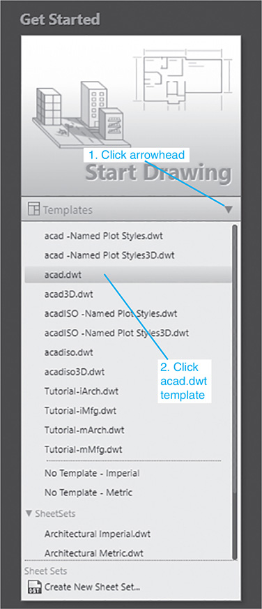
Figure 1-1
 Click acad.dwt on the Templates listing.
The drawing screen will appear. See Figure 1-2. Note that the tool panels have a light colored background. This was done for printing clarity. Your background may be dark.
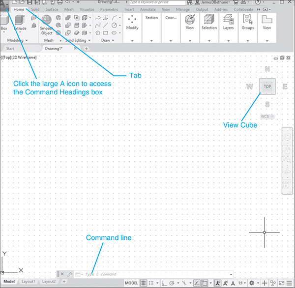
Figure 1-2
An Alternative Method to Starting a New Drawing
- Click the large A, the Menu Browser, in the upper left corner of the drawing screen to access the Command Headings box.
A listing of command headings will appear. See Figure 1-3.

Figure 1-3
- Click the New command.
The Select template dialog box will appear. See Figure 1-4.
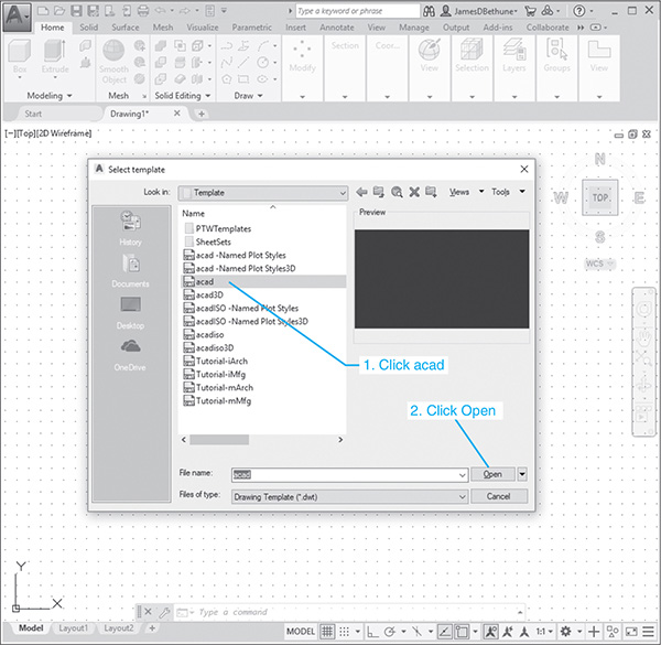
Figure 1-4
 Select the acad template and click the Open box.
The AutoCAD drawing screen will appear. See Figure 1-5. A group of tabs and panels will appear across the top of the screen. The tabs are used to access other groups of panels. Panels contain commands.
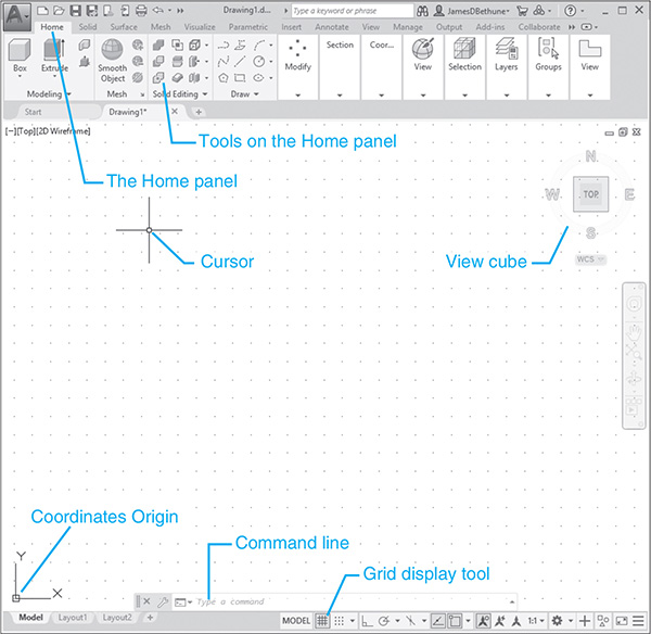
Figure 1-5
The command line is located at the bottom of the screen, as are other tools (icons) for commands such as Grid and Snap. The command line is used to type in inputs for the commands, among other uses.
The drawing’s name will appear at the top of the screen. In this example, the drawing name is Drawing1.dwg. This is a default name created by AutoCAD. If a drawing name had been entered, it would appear where the Drawing1.dwg title currently appears.
The bottom left corner of the drawing screen shows the coordinate display position of the horizontal, vertical crosshairs in terms of an X,Y coordinate value, whose origin is the lower left corner of the drawing screen.
The large open area in the center of the screen is called the drawing screen or drawing editor. Drawings are created in this area.
1-2 Tabs and Panels
The headings across the top of the screen (Home, Insert, etc.) are called tabs, and the groups of commands under the tabs are called panels. Figure 1-6 shows the Home panels and the Annotate panels.

Figure 1-6
To Access Additional Commands Within a Panel
Each panel shows a group of the most used commands. Additional commands are available by clicking the arrow to the right of the panel’s name. Figure 1-7 shows the additional Draw commands available.

Figure 1-7
Help Boxes for Commands
A help box will appear for a command if the cursor is located and held on the command’s icon. See Figure 1-7. Initially, when a cursor is located on a command icon, but not clicked, an identifying box will appear identifying the command. After a few seconds the box will expand to define the command.
To Access Other Help Information
If you cannot find a command or need further instructions for operating a particular command, click the Access to Help tool located at the top right section of the screen. See Figure 1-8. The icon for the Access to Help tool is a question mark within a circle. The Help dialog box will appear. Type in the name of what you are seeking, and click the magnifying glass icon just to the right of the search box.

Figure 1-8
1-3 The Command Line Box
The command line box is located at the bottom of the drawing screen. It can be used to access commands that do not have their own icons or to select options associated with the command. Figure 1-9 shows a circle. The word CIRCLE will automatically appear in the command box when the Circle tool is clicked on the Draw panel. As presented, the circle will be defined by using a radius value. Enter the radius value into the box with the blue background before clicking the left mouse button to complete the circle. If the radius value does not appear, click the Dynamic Input tool at the bottom of the drawing screen and ensure that the Dynamic Input is ON.
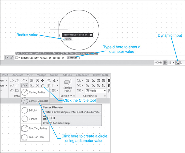
Figure 1-9
The command line shows the word Diameter in brackets: [Diameter]. This means that there is a diameter option.
To Enter a Diameter Value
- Click the Circle tool on the Home panel and draw a circle.
- Click the command line box.
- Type d; press Enter.
The system is now set for a diameter value for the circle.
 Enter a value for the diameter of the circle; press Enter.
The options shown in the command line box will always include one uppercase letter. It may not always be the first letter. Type that letter, and press Enter to access the option.
Diameter values may also be entered by first clicking the arrowhead next to the Circle tool and selecting the Center, Diameter option.
1-4 Command Tools
A tool is a picture (icon) that represents an AutoCAD command. Most commands have equivalent tools.
To Determine the Command That a Tool Represents
See Figure 1-10.
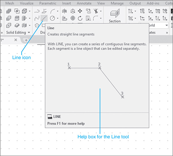
Figure 1-10
- Locate the cursor arrow on the selected tool (icon).
In the example shown, the Line command tool within the Draw panel was selected.
- Hold the arrow still without pressing any mouse buttons.
The command name will appear below the tool. This name is referred to as a tooltip.
If you continue to keep the cursor arrow on the tool box, a help box will appear.
1-5 Starting a New Drawing
When a new drawing is started, a drawing name is assigned, the drawing units are specified, the drawing limits are modified, if needed, and Grid and Snap values are defined. The following four sections will show how to start a new drawing.
1-6 Naming a Drawing
Any combination of letters and numbers may be used as a file name. Either uppercase or lowercase letters may be used, since AutoCAD file names are not case sensitive. The symbols $, -, and _ (underscore) may also be used. Other symbols, such as % and *, may not be used. See Figure 1-11.
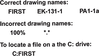
Figure 1-11
All AutoCAD drawing files will automatically have the extension .dwg added to the given file name. If you name a drawing FIRST, it will appear in the files as FIRST.dwg. Other extensions can be used, but the .dwg is the default setting. (A default setting is one that AutoCAD will use unless specifically told to use some other value.)
If you want to locate a file on another drive, specify the drive letter followed by a colon in front of the drawing name. For example, in Figure 1-11 the file specified C:FIRST will locate the drawing file FIRST on the C: drive.
To Start a New Drawing
There are three ways to access the Create New Drawing dialog box that is used to name a new drawing:
- Select the New tool from the Command Headings box. (See Figure 1-12.)

Figure 1-12
- Type the word new in response to a command prompt.
- Hold down the <Ctrl> key and press N.
Any of these methods will cause the Select template dialog box to appear on the screen. See Figure 1-13. The acad template will set up a drawing with inch values and ANSI style dimensions. The acadiso template will set up a drawing with millimeter values and ISO style dimensions.
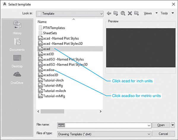
Figure 1-13
To Save a New Drawing File
A drawing name is entered as a file name by using the Save As option located in the Command Headings box. See Figure 1-14. It is recommended that a drawing name be assigned before a new drawing is started.

Figure 1-14
- Click the large A in the upper left corner of the screen.
- Select the Save As tool.
The Save Drawing As dialog box will appear. See Figure 1-15.

Figure 1-15
The Save Drawing As dialog box will list all existing drawings. Click on the thumbnail option to change the list to thumbnail drawings.
- Enter the drawing name.
In this example, the drawing name First was used.
- Select OK.
The name of the drawing will appear at the top of the screen. See Figure 1-16.

Figure 1-16
1-7 Drawing Units
AutoCAD 2020’s Drawing Units dialog box allows for either English or metric units to be used as default values; however, AutoCAD can work in any of five different unit systems: scientific, decimal, engineering, architectural, or fractional. The default system is the decimal system and can be applied to either English values (inches) or metric values (millimeters). See Figure 1-17.
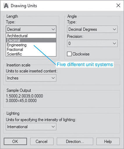
Figure 1-17
Access the Drawing Units command box by first clicking the large A at the top of the screen, and then the Drawing Utilities box.
To Specify or Change the Drawing Units
- Select the Drawing Utilities heading in the Command Headings box.
- Select Units. (See Figure 1-18.)
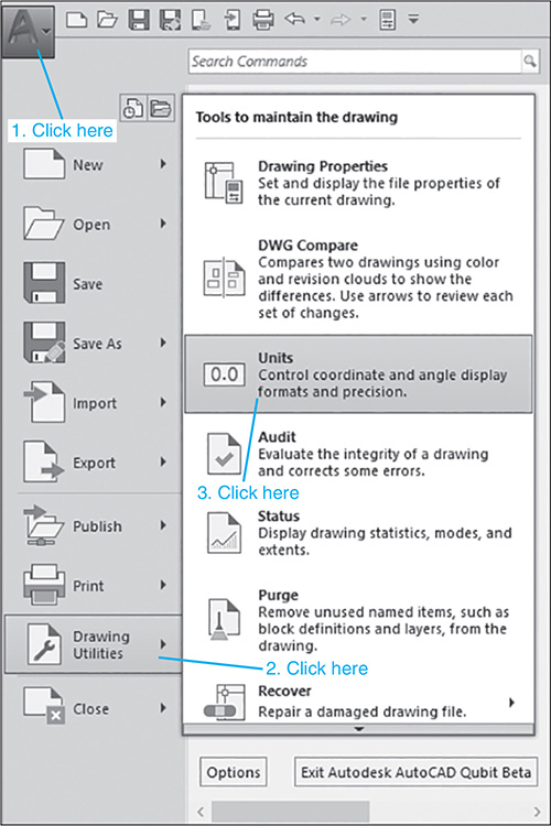
Figure 1-18
The Drawing Units dialog box will appear. See Figure 1-19.

Figure 1-19
- Select architectural units by clicking the arrow to the right of the Type box.
A listing of the five unit options will cascade down.
- Select Architectural.
Note that the Sample Output, located slightly below the center of the Drawing Units box, is in fractional inches.
 Repeat the procedure, and set the units back to Decimal.
To Specify or Change the Precision of the Units System
Unit values can be expressed with decimal places from zero to eight or in inches from 0 to 1/256 of an inch.
- Access the Drawing Units dialog box as explained previously.
- Select the arrow to the right of the current precision value display box below the word Precision.
A listing of the possible decimal precision values will cascade from the box. See Figure 1-20.
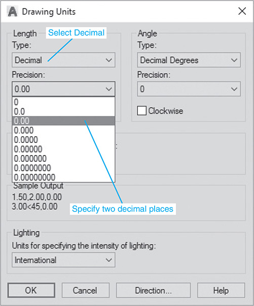
Figure 1-20
- Select 0.00.
The value 0.00 will appear in the Precision box.
- Select OK.
The original drawing screen will appear.
To Specify or Change the Angle Units Value
Angles may be specified in one of five different units: Decimal Degrees, Degrees/Minutes/Seconds, Gradians, Radians, or Surveyor units. Decimal Degrees is the default value.
Change the angle units by selecting the desired units in the cascade menu under Angle Type. The precision of the angle units is changed as specified for linear units.
1-8 Drawing Limits
Drawing limits are used to set the boundaries of the drawing. The drawing boundaries are usually set to match the size of a sheet of drawing paper. This means that when the drawing is plotted and a hard copy is made, it will fit on the drawing paper.
Figure 1-21 shows a listing of standard flat-size drawing papers for engineering applications, Figure 1-22 shows standard metric sizes, and Figure 1-23 shows standard architectural sizes.
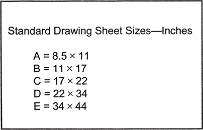
Figure 1-21

Figure 1-22

Figure 1-23
A standard 8.5" × 11" letter-size sheet of paper as used by most printers is referred to as an A-size sheet of drawing paper.
Note
A sheet of paper can be sized to match standard sheet sizes by the capabilities of the printer or plotter. Many printers and plotters have built-in scaling features, and some list standard sheet sizes that can be applied to a drawing.
To Align the Drawing Limits with a Standard A3 (Metric) Paper Size
- Click the large A, the Menu Browser, in the upper left corner of the screen.
- Click the Print command, and then click the Page Setup option.
See Figure 1-24. The Page Setup Manager dialog box will appear.

Figure 1-24
- Click the Modify . . . option.
See Figure 1-25. The Page Setup Model dialog box will appear.

Figure 1-25
- Click the arrow to the right of the Paper size box.
A listing of available paper sizes will cascade down. See Figure 1-26.
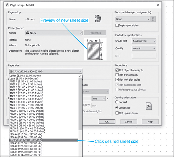
Figure 1-26
- Select the ISO A3 (420.00 × 297.00) size.
The dimensions in the preview box in the Printer/Plotter dialog box will change to the selected values.
 Click OK.
The drawing screen is now sized to the 420.00 × 297.00 ISO A3 dimensions.
Note
The sheet size may also be set with the Limits command. Type Limits in response to a command prompt, and define the drawing limits by defining the lower left corner of the drawing as 0.00,0.00 (this is the default setting) and the upper right corner as needed. If the new limits exceed the current screen limits, type zoom in response to a command prompt, then type a for Zoom All. The new drawing limits will be matched to the screen size. The default sheet size for an acad template is 8.5 × 11 (ANSI A), and for an acadiso template it is 210 × 297 (ISO A4).
1-9 Grid and Snap
The Grid command is used to place a grid background on the drawing screen. This background grid is helpful for establishing visual reference points for sizing and for locating points and lines.
Note
A dotted grid background is used throughout this book for purposes of clarity.
The Snap command limits the movement of the cursor to predefined points on the screen. For example, if the Snap command values are set to match the Grid values, the cursor will snap from intersection to intersection on the grid.
The default Grid and Snap setting for the acad template is .50 inch, and the default setting for Grid and Snap for the acadiso template is 10 millimeters.
Note
The Grid function can be toggled off and on with the <F7> key, and the Snap function can be toggled with the <F9> key.
To Set the Grid and Snap Values
- Start a new drawing, and select an acadiso (values are in millimeters) template.
- Right-click the Snap tool located at the bottom of the screen, and click the Snap Settings option.
See Figure 1-27.
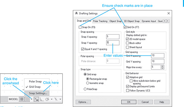
Figure 1-27
The Drafting Settings dialog box will appear. See Figure 1-27. If necessary, click the Snap and Grid tab.
- Click on the Grid On and Snap On boxes. A check mark will appear in the boxes.
- Place the cursor on the Snap X spacing box to the right of the given value under the Snap On heading.
A vertical flashing cursor will appear.
- Backspace out the existing value, and type in 5.
- Click the Snap Y spacing box.
The Y spacing will automatically be made equal to the X spacing value. Rectangular grid spacing can be created by specifying different X and Y spacing values.
 Select the Grid X spacing box under the Grid spacing heading.
 Backspace out the existing value, and type in 10 if needed.
 Click the Grid Y spacing box to make the X and Y values equal.
 Select OK.
See Figure 1-28. Since the Snap values have been set to exactly half of the Grid values, the cursor can be located either directly on grid intersections or halfway between them.
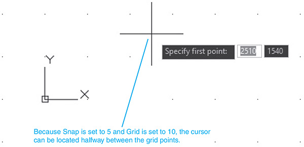
Figure 1-28
The grid can be turned on and off either by double-clicking the Grid icon at the bottom of the screen or by pressing the <F7> key on the keyboard. Snap can be turned on and off by double-clicking the Snap icon at the bottom of the screen or by pressing the <F9> key on the keyboard. Grid and Snap can also be activated by the tools on the status bar located at the bottom of the screen. See Figure 1-28.
1-10 Sample Problem SP1-1
Set up a drawing that will use millimeter dimensions and the following parameters:
Sheet size = 297,420(A3)
Grid = 10 spacing
Snap = 5 spacing
Whole-number precision
To Specify the Drawing Units
- Click the Menu Browser in the upper left corner of the drawing screen, and select the File command, then the New option.
The Select template dialog box will appear. See Figure 1-29.

Figure 1-29
- Select the acadiso template, then Open.
To Define the Drawing Precision
- Click the Menu Browser in the upper left corner of the drawing screen, and select the Drawing Utilities command, then the Units option.
The Drawing Units dialog box will appear. See Figure 1-30. In this example, only whole numbers will be used, so the 0 option is selected.
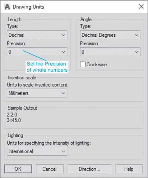
Figure 1-30
- Select the 0 precision, then OK.
To Calibrate the Sheet Size
The default values for an acadiso template are 210 × 297, but this sample problem calls for 297,420, an A3 sheet size.
- Click the Menu Browser, and select the Print option, then the Page Setup option.
The Page Setup Manager dialog box will appear.
- Click the Modify box.
The Page Setup – Model dialog box will appear. See Figure 1-31.

Figure 1-31
- Scroll down the available Paper size options, and select the ISO A3 (420.00 × 297.00) option.
- Click OK.
To Set the Grid and Snap Values
- Right-click the Grid icon at the bottom of the screen.
- Click the Grid Settings option.
The Drafting Settings dialog box will appear. See Figure 1-32.

Figure 1-32
- Turn the Grid and Snap commands on, and set the snap spacing for 5 and the grid spacing for 10.
- Type the word zoom in response to a command prompt. Then type A; press Enter.
The screen is now ready for starting a drawing by using millimeter values.
Note that the display dotted grid options have been turned on, generating a dotted rather than a lined grid.
1-11 Save and Save As
The Save and Save As commands are used to save a drawing.
To Use the Save and Save As Commands
- Click the Save As tool at the top of the screen located above the Home panel.
The Save Drawing As dialog box will appear. See Figure 1-33. In this example, the file name Drawing1.dwg appears. This is the default name that was created automatically when the new drawing was created.

Figure 1-33
- Save the drawing in the folder A20 located in the Document file, and enter the name Box. See Figure 1-34.

Figure 1-34
Note
The Open option can also be accessed by pressing <Ctrl> + <o>.
- Click the Save box.
1-12 Open
The Open command is used to call up an existing drawing so that you may continue working on it or revise it.
To Use the Open Command
The Open command may be accessed in one of two ways:
- Click the Open tool located on the Home panel next to the Save As icon.
The Select File dialog box will appear. See Figure 1-35.

Figure 1-35
- Click the Views option at the top of the Select File dialog box, and click the Thumbnails and Preview options.
Thumbnails of the drawing files will appear.
- Click the desired file.
A preview will appear.
- Click the Open box.
1-13 Close
The Close command allows you to close the current drawing.
- Click the Menu Browser, click Close, and then click Current Drawing.
See Figure 1-36. The system will exit the AutoCAD program.
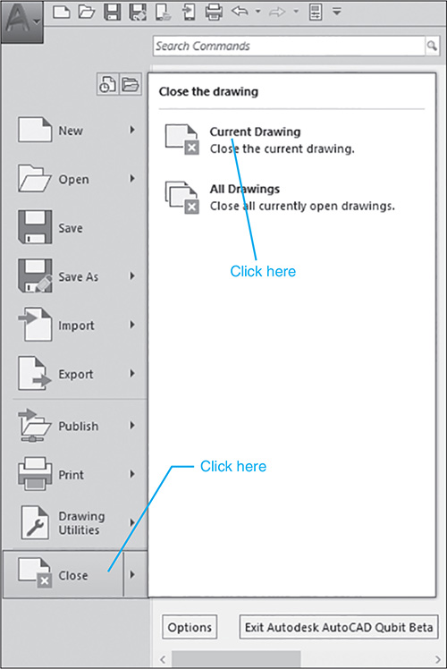
Figure 1-36
1-14 EXERCISE PROBLEMS
EX1-1
Create a drawing screen as shown in Figure EX1-1. Select an acadiso template, turn on the Grid and Snap functions, and set the grid spacing for 10 and snap spacing for 5. Set the sheet size for (A3 297 x 420). Name the drawing Screen 1.

EX1-2
Create a drawing screen as shown in Figure EX1-2. Select an acad template, turn on the Grid and Snap functions, and set the grid spacing for 0.50 and snap spacing for 0.25. Locate the origin in the lower left corner of the drawing screen. Name the drawing Screen 2.

EX1-3
Create a drawing screen as shown in Figure EX1-3. Select an acadiso template, turn on the Grid and Snap functions, and set the grid spacing for 50 and snap spacing for 10. Set the grid background for dotted. Name the drawing Screen 3.

EX1-4
Create a drawing screen as shown in Figure EX1-4. Select an acadiso3D template, turn on the Grid and Snap functions, and set the grid spacing for 20 and snap spacing for 5. Name the drawing Screen 4-3D.
