
Chapter 4 Sketching
4-1 Introduction
The ability to create freehand sketches is an important skill for engineers and designers to acquire. The old joke about engineers and designers not being able to talk without a pencil in their hand is not far from the truth. Many design concepts and ideas are very difficult to express verbally, so they must be expressed visually. Sketches can be created quickly and used as a powerful aid in communicating technical ideas.
This chapter presents the fundamentals of freehand sketching as applied to technical situations. It includes both two-dimensional and three-dimensional sketching. Like any skill, freehand sketching is best learned by lots of practice.
4-2 Establishing Your Own Style
As you learn how to sketch and practice sketching, you will find that you develop your own way of doing things, your own style. This is very acceptable, as there is no absolutely correct method for sketching, but only recommendations.
The most important requirement of freehand sketching is that you be comfortable. As you practice and experiment, you may find that you prefer a certain pencil lead hardness, a certain angle for your paper, and a certain way to make your lines, both straight and curved. You may find that you prefer to use oblique sketches rather than isometric sketches when sketching three-dimensional objects. Eventually, you will develop a style that is comfortable for you and that you can consistently use to create good-quality sketches.
It is recommended that you try all the types of sketches presented in the chapter. Only after you have tried and practiced all of the different types will you be able to settle on a technique and style that works best for you.
4-3 Graph Paper
Graph paper is very helpful when preparing freehand sketches. It helps you to sketch straight lines, allows you to set up guide points for curved lines, and can be used to establish proportions. It is recommended that you start by doing all two-dimensional sketches on graph paper. As your sketching becomes more proficient, you may sketch on plain paper, but because most technical sketching requires some attention to correct proportions, grid paper will always be helpful.
Graph paper is available in many different scales and in both inch and metric units. Some graph paper is printed with light-blue lines, since many copying machines cannot easily reproduce blue lines. This means that copies of the sketches done on light-blue guidelines will appear to have been drawn on plain paper and will include only the sketch.
4-4 Pencils
Pencils are made with many grades of lead hardness. See Figure 4-1. Hard leads can produce thin, light lines and are well suited for the accuracy requirements of board-type drawings, but are usually too light for sketching. The soft leads produce broad, dark lines, but tend to smudge easily if handled too much.

Figure 4-1
The choice of lead hardness is a personal one. Some designers use 3H leads very successfully; others use HB leads with equally good results. You are probably used to a 2H lead, as this is the most commonly available. Start sketching with a 2H lead, and if the lines are too light, try a softer lead; if they are too dark, try a harder lead until you are satisfied with your work. Pencils with different grades of lead hardness are available at most stationery and art supply stores.
Most sketching is done in pencil because it can easily be erased and modified. If you want the very dark lines that ink produces, it is recommended that you first prepare the drawing in pencil and then use a pen to trace over the lines that you want to emphasize.
4-5 Lines
Straight lines are sketched by one of two methods: by drawing a series of short lines—called feathering—or by drawing a series of line segments. The line segments should be about 1 to 2 inches or 25 to 50 millimeters long. It is very difficult to keep the line segments reasonably straight if they are much longer. As you practice you will develop a comfortable line segment length. See Figure 4-2.

Figure 4-2
Lines may also be sketched as long, continuous lines. First, locate the pencil at the line’s starting point; then, look at the endpoint as you sketch. This will help you develop straighter long lines. Continuous lines are best sketched on graph paper because the graph lines will serve as an additional guide for keeping the lines straight.
Long lines can be created by a series of shorter lines, and very long lines can be sketched by first defining a series of points, then using short segments to connect the points.
It is usually more comfortable to turn the paper slightly when sketching, as shown in Figure 4-3. Right-handers turn the paper counterclockwise, and left-handers, clockwise.

Figure 4-3
It is also easier to sketch all lines in the same direction—that is, with your hand motion always the same. Rather than change your hand position for lines of different angles, simply change the position of the paper and sketch the lines as before. Horizontal and vertical lines are sketched by using exactly the same motion; the paper is just turned 90°. Straight lines of any angle can be sketched in the same manner.
Sketch lines by using a gentle, easy motion. Don’t squeeze the pencil too hard. Sketch lines with more of an arm motion than a wrist motion. If too much wrist motion is used, the lines will tend to curve down at the ends and look more like arcs than straight lines.
4-6 Proportions
Sketches should be proportional. A square should look like a square, and a rectangle like a rectangle. Graph paper is very helpful in sketching proportionally, but it is still sometimes difficult to be accurate even with graph paper. Start by first sketching very lightly and then checking the proportionality of the work. See Figure 4-4. Go back over the lines, making corrections if necessary, and then darken in the lines. The technique of first sketching lightly, checking the proportions, making corrections, and then going over the lines is useful regardless of the type of paper used.

Figure 4-4
It is often helpful to sketch a light grid background based on the unit values of the object being sketched. This is true even if you are working on graph paper because it helps to emphasize the unit values you need. See Figure 4-5.

Figure 4-5
The exact proportions of an object are not always known. A simple technique to approximately measure an object is to use the sketching pencil. See Figure 4-6. Hold the pencil at arm’s length and sight the object. Move your thumb up the pencil so that the distance between the end of the pencil and your thumb represents a distance on the object. Transfer the distance to the sketch. Continue taking measurements and transferring them to the sketch until reasonable proportions have been created.

Figure 4-6
4-7 Curves
Curved shapes are best sketched by first defining points along the curve, then lightly sketching the curve between the points. See Figure 4-7. Evaluate the accuracy and smoothness of the curve, make any corrections necessary, and then darken in the curve.

Figure 4-7
Circles can be sketched by sketching perpendicular centerlines and marking off four points equally spaced from the center point along the centerlines. The distance between the center point and the points on the centerlines should be approximately equal to the circle’s radius. See Figure 4-8.

Figure 4-8
Draw a second set of perpendicular centerlines approximately 45° to the first. Again mark four points approximately equal to the radius of the circle. Sketch a light curve through the eight points, and check the curve for accuracy and smoothness. Make any corrections necessary, and darken in the circle.
An ellipse can be sketched by first sketching a perpendicular axis, and then locating four marks on the centerlines that are approximately equal to major and minor axis distances. Sketch a light curve, make any corrections necessary, and darken in the elliptical shape. See Figure 4-9.

Figure 4-9
Figure 4-10 shows how to sketch a slot. To sketch the slot, centerlines for the two end semicircles are located and sketched. Two additional radius points are added, and then the overall shape of the slot is lightly sketched. Corrections are made, and the final lines are darkened.

Figure 4-10
The triangular object is first sketched as a triangle, guidelines and axis are added for the curved sections, and the final shape of the object is sketched.
4-8 Sample Problem SP4-1
Sketch the object shown in Figure 4-11.

Figure 4-11
 Sketch the overall rectangular shape of the object. See Figure 4-12.
Figure 4-12
 Add proportional guidelines for the outside shape of the object, and lightly sketch the outside shape.
 Locate and sketch guidelines and axis lines for the other features.
 Lightly sketch the object, and make any corrections necessary.
 Darken the final lines.
4-9 Isometric Sketches
Isometric sketches are based on an isometric axis that contains three lines, 120° apart. See Figure 4-13. The isometric axis can also be drawn in a modified form that contains a vertical line and two 30° lines. The modified axis is more convenient for sketching and is the more commonly used form. See Figure 4-14.

Figure 4-13

Figure 4-14
The receding lines of an isometric sketch are parallel. This is not visually correct, as the human eye naturally sees objects farther away as smaller than those closer. In reality, railroad tracks appear to converge; however, it is easier to draw objects with parallel receding lines, and if the object is not too big, the slight visual distortion is acceptable. See Section 4-12 for an explanation of perspective drawings whose receding lines are not parallel, but convergent.
The three planes of an isometric axis are defined as the left, right, and top planes, respectively. See Figure 4-14. When creating isometric sketches, it is best to start with the three planes drawn as if the object were a rectangular prism or cube. Think of creating the sketch from these planes as working with a piece of wood, and trim away the unnecessary areas. Figure 4-15 shows an example of an isometric sketch. In the example, the overall proportions of the object were used to define the boundaries of the object, and then other surfaces were added as necessary.

Figure 4-15
Isometric sketches may be sketched in different orientations. Figure 4-16 shows six possible orientations. Note how orientation 1 makes the object look as if it is below you, and orientation 6 makes it look as if it is above you. Orientation can also serve to show features that would otherwise be hidden from view. The small cutout is clearly visible in only one of the orientations. Always try to orient the isometric sketch so that it shows as many of the object’s features as possible.

Figure 4-16
Figure 4-17 shows an isometric drawing of a cube that has a hole in the top plane. The hole must be sketched as an ellipse to appear visually correct in the isometric drawing. The axis lines for the ellipse are parallel to the edge lines of the plane. The proportions of the ellipse are defined by four points equidistant from the ellipse center point along the axis lines. The ellipse is then sketched lightly, checked for accuracy, and darkened.

Figure 4-17
4-10 Sample Problem SP4-2
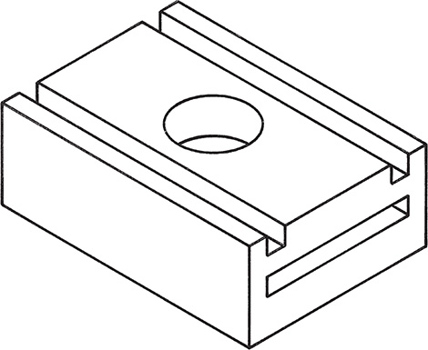
Sketch the object shown in Figure 4-18. Do not include dimensions, but keep the object proportional.

Figure 4-18
- Use the overall dimensions of the object to sketch a rectangular prism of the correct proportions. This is a critical step. If the first attempt is not proportionally correct, erase it and sketch again until a satisfactory result is achieved. See Figure 4-19.
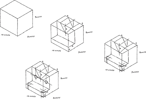
Figure 4-19
- Sketch the cutout.
- Sketch the rounded surfaces. Note how axis lines are sketched and the elliptical shape added. Tangency lines are added, and visually incorrect lines are erased.
- Sketch the holes. The holes are located by locating their centerlines and then sketching the required ellipses.
4-11 Oblique Sketches
Oblique sketches are based on an axis system that contains one perpendicular set of axis lines and one receding line. See Figure 4-20. The front plane of an oblique axis is perpendicular, so the front face of a cube will appear as a square and the front face of a cylinder as a circle. The receding lines can be at any angle, but 30° is most common.

Figure 4-20
The receding lines of oblique sketches are parallel. As with isometric sketches, this causes some visual distortions, but unless the object is very large, these distortions are acceptable.
Holes in the front plane of an oblique sketch may be sketched as circles, but holes in the other two planes are sketched as ellipses. See Figure 4-21. The axis lines for the ellipse are parallel to the edge lines of the plane. The proportions of the ellipses are determined by points equidistant from the center point along the axis.

Figure 4-21
Figure 4-22 shows an example of a circular object sketched as an oblique sketch. Oblique sketches are particularly useful in sketching circular objects because they allow circles in the frontal planes to be sketched as circles rather than the elliptical shapes required by isometric sketches.

Figure 4-22
Figure 4-23 shows an object. Figure 4-24 shows how an oblique sketch of the object was developed.

Figure 4-23

Figure 4-24
4-12 Perspective Sketches
Perspective sketches are sketches whose receding lines converge to a vanishing point. Perspective sketches are visually accurate in that they look like what we see: Objects farther away appear smaller than those that are closer.
Figure 4-25 shows a comparison among the axis systems used for oblique, isometric, and two-point perspective drawings. The receding lines of the perspective drawings converge to vanishing points that are located on a theoretical horizon. The horizon line is always located at eye level. Objects above the horizon line appear to be above you, and objects below the horizon appear to be below you.

Figure 4-25
Perspective drawings are often referred to as pictorial drawings. Figure 4-26 shows an object drawn twice: once as an isometric drawing and again as a pictorial, or two-point, perspective. Note how much more lifelike the pictorial drawing looks in comparison with the isometric drawing.

Figure 4-26
Figure 4-27 shows a perspective sketch based on only one vanishing point. One-point perspective sketches are similar to oblique sketches. The front surface plane is sketched by using a 90° axis, and then receding lines are sketched from the front plane to a vanishing point. As you practice sketching, eventually you will not need to include a vanishing point, but will imply its location.

Figure 4-27
Figure 4-28 shows how to sketch circular shapes in one- and two-point perspective sketches. In each style, the axis lines consist of a vertical line and a line that is aligned with the receding edge lines. Circular shapes in perspective drawings are not elliptical, but are irregular splines. Each surface will require a slightly different shape, depending on the angle of the receding lines, to produce a visually accurate circular shape.

Figure 4-28
4-13 Working in Different Orientations
It is important for a designer to be able to sketch an object in different orientations in order to present a clear representation of all of the design’s different facets.
Figure 4-29 shows three different objects sketched in three different orientations. Each sketch used an isometric format. Proportions for each object were determined by using the dot grid background.

Figure 4-29
4-14 Exercise Problems
Sketch the shapes in Exercise Problems EX4-1 through EX4-6. Measure the shapes to determine their dimensions.
EX4-1

EX4-2

EX4-3

EX4-4

EX4-5

EX4-6

Prepare isometric or perspective sketches of the objects shown in Exercise Problems EX4-7 through EX4-18. Measure the objects to determine their dimensions.
EX4-7

EX4-8

EX4-9

EX4-10

EX4-11

EX4-12
EX4-13

EX4-14

EX4-15

EX4-16

EX4-17

EX4-18

Prepare oblique or perspective sketches of the objects shown in Exercise Problems EX4-19 through EX4-22. Measure the objects to determine their dimensions.
EX4-19

EX4-20

EX4-21

EX4-22

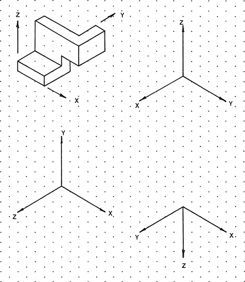
Prepare isometric sketches of the shapes that follow, each in the given orientation, and then sketch the objects in the three different orientations defined by the X,Y,Z axes. Assume that the spacing between dots in the background grid is approximately 0.25 inch, or 10 millimeters.
EX4-23

EX4-24

EX4-25

EX4-26

EX4-27

EX4-28

EX4-29
EX4-30

EX4-31

EX4-32

EX4-33

EX4-34

EX4-35

EX4-36

EX4-37

EX4-38

EX4-39

EX4-40

EX4-41

EX4-42

EX4-43

EX4-44

EX4-45

EX4-46

EX4-47

EX4-48

EX4-49

EX4-50

Sketch the following objects.
EX4-51

EX4-52

EX4-53

EX4-54
