
In previous chapters, you reviewed IPSec VPN fundamentals and design principles in depth. This chapter explores a new type of VPN service known as the network-based VPN.
In a customer edge (CE) VPN or CE-based VPN that uses IPSec, all VPN configuration, encapsulation, and decapsulation is performed by the CEs. The provider network that provides connectivity to the CEs is simply providing a transport service to the CEs and is oblivious of the VPN configuration. In a network or provider edge–based VPN, all VPN configuration, encapsulation, and decapsulation is performed at the provider edge (PE); the CEs in this case are oblivious of the VPN configuration. Figure 9-1 shows a popular PE-based VPN defined in RFC 2547 using Multiprotocol Label Switching (MPLS).

All the tunneling of CE-CE traffic in the MPLS VPN shown in Figure 9-1 is performed by the PE routers at the edge of the service provider network. MPLS VPNs have several advantages over the traditional overlay CE-based IPSec VPNs. Some salient advantages of PE-based VPNs over CE-based VPNs are as follows:
Increased scalability—. To connect N sites of an IPSec VPN for any-to-any connectivity, each CE will need (N-1) tunnels to every other CE. This means that every CE has to be able to deal with this scalability requirement, thereby increasing the cost of the CEs at sites where such a large CE may not be required. In contrast, the same any-to-any connectivity can be established between CEs of an MPLS VPN with a single connection from a CE to the PE. Also, the encapsulation and decapsulation is performed by the PE routers, thereby reducing the cost of the CE by not requiring expensive hardware encryption at the CE.
Greatly simplified configuration—. Every time a new site is added to a CE-based IPSec VPN, the configuration has to be changed in (N-1) sites for any-to-any connectivity. In an MPLS-VPN, only the configuration of the PE and the attached CE is changed; none of the remote CEs or remote PEs is affected. In other words, configuration complexity of MPLS-based VPNs is O(1) compared to O(n) for IPSec-based VPNs. This means that it is operationally easier and more economical for a service provider to provision an MPLS-based VPN.
Note
One could argue that DMVPN (see Chapter 7, “Auto-Configuration Architectures for Site-to-Site IPSec VPNs”) reduces configuration complexity, negating this advantage for MPLS VPN. But DMVPN also requires a dynamic routing protocol such as OSPF in the overlay tunnels, which has limitations as the number of sites of the VPN grows very large.
One of the primary limitations of MPLS VPN architecture is the requirement for each CE to have physical connectivity at Layer 2 to its corresponding PE. Now, imagine a service provider that is offering an MPLS VPN service to its customers. In this scenario, assume that one customer has five sites that need to be connected over the VPN and that the service provider has a point of presence (POP) in only four of the five locations—which means only four of the sites can be part of the VPN. The following list presents the options available for the service provider to connect the fifth site to the VPN:
Option 1—. The service provider can extend its backbone network and build a new POP in the new location. Although the most obvious solution, this option is usually not cost effective for the service provider and in some cases is simply not viable.
Option 2—. The service provider may backhaul the customer’s traffic across other providers using leased lines. This option is the next obvious option, but is also cost prohibitive, has long installation lead times, and may be subject to frequent outages.
Option 3—. Connect the fifth site to the VPN via IPSec tunnels over the public Internet to every other site. However, there are several disadvantages of this option:
Each site of this VPN now requires a CE that is IPSec-capable.
IPSec requires (public) reachability to each CE endpoint. If the IPSec tunnels to each site have to traverse the Internet, all the CEs at the sites need IP reachability over the Internet, which might not be possible.
Every site is exposed to the Internet and may require more security protection mechanisms.
Option 4—. Build an IPSec tunnel from the remote CE to the service provider PE and map the IPSec tunnel into the appropriate MPLS VPN at the PE. This option is called the Network Based IPSec VPN solution, which is the subject of this chapter. Figure 9-2 illustrates this option. This would be a secure and cost-effective option.

There are several advantages of the Network Based IPSec VPN architecture:
The PE and CE need only IP connectivity; no dedicated Layer 2 connection is required.
Connectivity to the four original sites is retained via the MPLS VPN and no additional configuration is needed on the sites to connect the fifth site to the VPN.
Optimal routing from site to site is possible without a full-mesh configuration.
Secure connectivity for the new “off net” site. This is important because traffic from this site routinely transits the public Internet.
The rest of this chapter is dedicated to this architecture and presents the configuration and design of network-based VPNs.
You have seen conceptually how a network-based IPSec VPN solution enables service providers to expand their VPN portfolio with secure off-net remote access and remote site-to-site services. This section focuses on understanding IOS features that are key to implementing this solution.
The following three key features will be discussed:
Virtual Routing and Forwarding (VRF) tables
Crypto keyrings
ISAKMP profiles
The notion of a VRF table was defined in RFC 2547 for MPLS VPNs. As the name suggests, a VRF is a unique routing and forwarding table per VPN. A given PE router may be connected to sites from different VPNs and hence may have multiple VRFs. To provide per-VPN routing segregation and avoid accidentally forwarding packets from one VPN to another, VRFs are kept on the PE routers.
A CE connected to a PE is associated with a VPN by explicit configuration of the VRF on the PE interface connecting the CE. The association between a given VRF and its attached set of interfaces or subinterfaces is determined by explicit configuration.
When a packet arrives from a CE, the routing or forwarding lookup for the destination is performed in the associated VRF table ensuring packets are only forwarded to destinations in the VRF. The VRF itself is populated by learning IPv4 routes from the CE by typical routing protocols such as OSPF, eBGP, static, RIPv2, and EIGRP. The PE advertises the routes learned from the CE to all other PEs via multiprotocol extensions to BGP (MP-BGP). The routes advertised by the PE via MP-BGP are known as VPNv4 routes. A couple of key attributes that are tagged to the VPNv4 routes in MP-BGP are the route target (RT) and the route distinguisher (RD).
The RD enables overlapping address pools between VPNs or VRFs, whereas the RT determines the distribution of the routes into the remote PE’s VRF. Both attributes are manually configured.
You learned in previous chapters that when you configure IPSec, you must configure the Internet Security Association and Key Management Protocol (ISAKMP) policies. If the authentication scheme used is a pre-shared key, then you have to configure the corresponding key for each IPSec endpoint. In the traditional IPSec model, all the IPSec terminations are for connectivity into a single IPSec VPN, whereas in the network-based IPSec model you need to terminate IPSec tunnels belonging to different VPNs on the same IPSec aggregator. This means you need a mechanism to demarcate the keys of different VPNs, which is exactly what crypto keyrings are about.
With crypto keyrings, each VPN has its own unique keyring. Example 9-1 shows crypto keyrings for two different VPNs. A crypto keyring is in use if it is attached to one or more ISAKMP profiles. A crypto keyring cannot be deleted while it is in use by one of the profiles.
Example 9-1. Crypto Keyring Configuration
crypto keyring vpn1
  description keys for vpn1
  pre-shared-key address 9.1.1.145 key vpn1aes
crypto keyring vpn2
  description keys for vpn2
  pre-shared-key address 9.1.1.149 key vpn2ikev2
If the VRF keyword is not specified in the crypto keyring command, the keyring is bound to the global VRF (global routing table). When a VRF keyword is used in the command, the keyring is associated with the front-door VRF (FVRF). Example 9-2 shows keyring vpn1 bound to front-door VRF vpn1. The concepts of FVRF and inside VRF (IVRF) will be explained in the “Operation of Network-Based IPSec VPNs” section, later in this chapter.
An ISAKMP profile can be viewed as a placeholder for holding phase 1 and phase 1.5 (x-auth/mode-cfg) configuration applicable to an aggregation of peers. The ISAKMP profile selected for a specific peer during Internet Key Exchange (IKE) negotiation can be identified by using one of the following:
Phase 1 IKE identity. The identities could be of type IP Address, FQDN, USER-FQDN, DN, and ID_KEY_ID.
Matching fields in the certificate forwarded by the peer during authentication.
Note
It is important to note that the isakmp profile does not specify ISAKMP policy. Policy is still defined globally because ISAKMP policy selection has to be done prior to knowing the ISAKMP profile when Main Mode is used.
After the identity is matched and IKE phase 1 is complete, the IPsec user or branch site is bound to the appropriate VRF configured on the ISAKMP profile.
Example 9-3 shows the ISAKMP profile configuration with match identity statements using IP address, FQDN, USER_FQDN, and ID_KEY_ID, respectively. As you saw in Chapter 4, “IPSec Authentication and Authorization Models,” ID_KEY_ID is the groupname for Cisco Unity clients. You can also see that in the case of remote access, you can configure all the AAA attributes within the ISAKMP profile, as shown in Example 9-3.
Example 9-3. ISAKMP Profile Configuration
crypto isakmp profile vpn1
 vrf vpn1 description IVRF
 keyring vpn1
 match identity address 9.1.1.145 255.255.255.255
 match identity hostname domain vpn1.com
 accounting vpn
!
crypto isakmp profile vpn1-ra
  vrf vpn1
  match identity user-fqdn [email protected]
  match identity group vpn1group
  client authentication list vpn
  isakmp authorization list vpn
  client configuration address respond
  accounting vpn
If the FVRF interface is in a VRF (not in global), then you must make sure there is a configuration that has the match identity statement with the VRF option, as shown in Example 9-4.
Example 9-4. Configuration Showing FVRF Association with Match Identity for Site-to-Site IPSec VPNs
crypto isakmp profile vpn2
 vrf vpn2
 keyring vpn2
 match identity address 9.1.1.149 255.255.255.255 vrf vpn2
 accounting vpn
If the match criteria for the selection of the ISAKMP profile is based on certificates, then define the corresponding certificate map and assign that map to the match certificate, as shown in Example 9-5.
Example 9-5. Use of Certificates to Bind to a Profile and VRF
crypto isakmp profile vpn1-ra
  vrf vpn1
  ca trustpoint vpn1
  match certificate foo
  client configuration group vpn1group
  client authentication list vpn
  isakmp authorization list vpn
  client configuration address respond
  accounting vpn
!
crypto ca certificate map foo
 subject-name co ou=EAST
 subject-name co o=VPN1
The main reason for using certificate matching is for cases in which the assignment of an ISAKMP profile cannot depend solely on the identity sent by the peer, and the intent is to be much more granular. For telecommuter clients wherein the group information cannot be retrieved from the certificate, you can assign a group to the clients.
Note
The ISAKMP profile must specify at least one “match” subcommand. An ISAKMP profile is regarded as incomplete without a match statement, and any traffic that matches a crypto map to which such a profile is attached will be dropped.
Any number of match statements can be specified in a single ISAKMP profile. The match statements should be used with care. An incoming identity will be matched in accordance with the following rules:
If the identity is of type IP address, the keyring and the match statement will be used. No two profiles should include the same match identity address and a common keyring. For identities of type ID_FQDN, or ID_USER_FQDN, the longest match will be chosen as the correct match.
Now that you have an understanding of the key features in IOS for network-based IPSec VPNs, you are ready to examine the operation of this solution. One of the primary motivations for a network-based IPSec VPN is to extend the service provider’s footprint over the public Internet. There are several options a service provider has to provide this extension. One could make each PE router IPSec capable; another would be to have a set of dedicated IPSec PEs that is primarily used for this service. The latter is generally the more common approach given the financial considerations and the fact that not all PEs are IPSec capable.
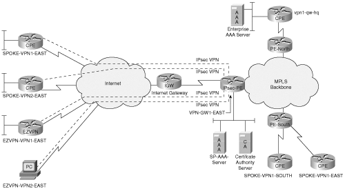
There are two deployment scenarios to offer this solution—one of them uses a single IP address on the PE reachable from the Internet for terminating IPSec tunnels of multiple VPNs and the second one uses a unique IP address per VPN on the terminating PE.
In an MPLS VPN, separation of a CE belonging to a particular VPN is made by explicitly configuring the PE-CE link on the PE to the appropriate VRF. Forwarding decisions for all traffic that is received from the CE are made by referencing the VRF that the PE-CE interface is configured with.
With an understanding of how MPLS VPNs operate, an obvious solution to extend reachability of the CEs across the Internet is to have a dedicated interface facing the Internet explicitly configured in a VRF and terminating IPSec tunnels from the corresponding CEs across the Internet into its VRF interface. Although this solution works, it requires a unique IP address or sub-interface per VRF that is reachable from the Internet.
A more elegant solution would be to use a single IP address for terminating the off-net IPSec tunnels, but this presents some interesting challenges. One issue is that a mechanism is needed to somehow separate the CEs belonging to different VPNs and map the traffic to the appropriate VRF.
The operation of mapping the IPSec tunnels into the appropriate VRFs involves several concepts mentioned earlier in this chapter and explained in the following section. One of these concepts is the concept of a front-door VRF (FVRF) and an inside VRF (IVRF).
Each IPSec tunnel is associated with two VRF domains. The outer IP header of the tunnel-mode IPSec encapsulated packet belongs to the FVRF, whereas the inner IP header is associated with the VPNs private IVRF. Figure 9-3 illustrates the concept of a FVRF and an IVRF. The FVRF pertains to the VRF that the encrypted packet itself is in. The FVRF is commonly on a global VRF. In this example, in which all the IPSec tunnels terminate on a single IP address on the PE facing the Internet, the global interface facing the Internet is considered to be in the FVRF. The IVRF is used for post-decryption forwarding lookups for IPSec traffic terminating on the aggregation PE.
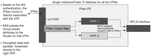
In this example, where all the IPSec tunnels terminate on a single IP address on the PE, the FVRF is the same and is set to the VRF configured on the Internet-facing interface. Traffic arriving from remote CEs that is associated with the IVRF is done during IKE negotiation using ISAKMP profiles.
Now that you have a conceptual understanding of FVRF and IVRF, this section will explore the configuration details and packet flow for the deployment scenario of a single IP address on the PE. The single IP address is used for terminating IPSec tunnels from remote sites and telecommuters that belong to multiple VPNs. Figure 9-4 illustrates this scenario.
The complete configuration of the PE router terminating the IPSec tunnels from remote CE sites belonging to multiple VPNs and telecommuters (also known as remote access clients) is shown in Example 9-6.
Example 9-6. Configuration of the PE (VPN-GW1-EAST)
vpn-gw1-east# show running-configuration

version 12.3
service timestamps debug datetime
service timestamps log datetime msec
no service password-encryption
!
hostname vpn-gw1-east
aaa new-model
!
aaa authentication login vpn1 group radius
aaa authorization network vpn1 group radius
aaa accounting update periodic 5
aaa accounting network vpn start-stop group radius
aaa session-id common
ip subnet-zero
!
!
!
!
ip vrf vpn1
 rd 200:1
 route-target export 200:1
 route-target import 200:1
!
ip vrf vpn2
 rd 201:1
 route-target export 201:1
 route-target import 201:1
!
ip cef
mpls label protocol ldp
tag-switching ip default-route
no ftp-server write-enable
!
crypto keyring vpn1
  pre-shared-key address 9.1.1.146 key vpn1aes
crypto keyring vpn2
  pre-shared-key address 9.1.1.150 key vpn2ikev2
!
crypto isakmp policy 1
 authentication pre-share
 group 2
crypto isakmp keepalive 10 10
crypto isakmp profile vpn1
   vrf vpn1
   keyring vpn1
   match identity address 9.1.1.146 255.255.255.255
crypto isakmp profile vpn1-ra
   vrf vpn1
   match identity group vpn1group
   client authentication list vpn
   isakmp authorization list vpn
   client configuration address respond
   accounting vpn
crypto isakmp profile vpn2
   vrf vpn2
   keyring vpn2
   match identity address 9.1.1.150 255.255.255.255
!
!
crypto ipsec transform-set vpn1 esp-3des esp-sha-hmac
crypto ipsec transform-set vpn2 esp-3des esp-md5-hmac
!
crypto dynamic-map dynamic 1
 set transform-set vpn1
 set isakmp-profile vpn1-ra
 reverse-route remote-peer 9.1.1.33
!
crypto map vpn 1 ipsec-isakmp
set peer 9.1.1.146
set transform-set vpn1
set isakmp-profile vpn1
reverse-route remote-peer address 9.1.1.33
match address 101

crypto map vpn 2 ipsec-isakmp
set peer 9.1.1.150
set transform-set vpn2
set isakmp-profile vpn2
reverse-route remote-peer address 9.1.1.33
match address 102

crypto map vpn 3 ipsec-isakmp dynamic dynamic
!
interface Loopback0
 ip address 9.2.1.100 255.255.255.255
!
interface FastEthernet0/0
 ip address 9.1.1.35 255.255.255.248
 duplex full
 crypto map vpn
!
interface FastEthernet2/0
 ip address 100.1.1.147 255.255.255.0
 duplex full
!
interface FastEthernet4/0
 ip address 9.2.1.1 255.255.255.252
 duplex full
 tag-switching ip
!
 router ospf 1
 log-adjacency-changes
 network 9.2.1.0 0.0.0.3 area 0
 network 9.2.1.100 0.0.0.0 area 0
!
router bgp 1001
 no synchronization
 bgp log-neighbor-changes
 neighbor 153.1.1.1 remote-as 1001
 neighbor 153.1.1.1 update-source Loopback0
 no auto-summary
 !
 address-family vpnv4
 neighbor 153.1.1.1 activate
 neighbor 153.1.1.1 send-community extended
 exit-address-family
 !
 address-family ipv4 vrf vpn2
 redistribute connected
 redistribute static
 no auto-summary
 no synchronization
 exit-address-family
 !
 address-family ipv4 vrf vpn1
 redistribute connected
 redistribute static
 no auto-summary
 no synchronization
 exit-address-family
!
ip local pool vpn1pool 10.254.245.1 10.254.254.254 group vpn1group
ip classless
ip route 0.0.0.0 0.0.0.0 9.1.1.33
access-list 100 permit ip 10.0.1.0 0.0.0.255 any
access-list 101 permit ip 10.0.1.0 0.0.0.255 any
no ip http server
no ip http secure-server
!
radius-server host 100.1.1.4 auth-port 1645 acct-port 1646
radius-server key cisco
radius-server vsa send accounting
!
end

vpn-gw1-east#
We’ll parse the configuration on the PE/IPSec aggregator shown in Example 9-6 to illustrate how the association of the inner IP header of the IPSec packet to the IVRF takes place. In this example, the MPLS-PE at the edge of the service provider network is also the IPSec aggregator. We will divide the PE configuration in Example 9-6 into three parts:
The first part is the generic MPLS-VPN configuration.
The second part of the configuration is relevant to the termination of the IPSec tunnel from a remote-site CE.
The third part is relevant to the IPSec tunnel termination from a remote access client or a telecommuter.
Example 9-7 shows the parts of the configuration that are relevant to the generic MPLS VPN configuration of the PE router.
Example 9-7. MPLS VPN Relevant Configuration on the PE
ip vrf vpn1
 rd 200:1
 route-target export 200:1
 route-target import 200:1
!
ip vrf vpn2
 rd 201:1
 route-target export 201:1
 route-target import 201:1
!
mpls label protocol ldp
!
interface FastEthernet0/0
 ip address 9.1.1.35 255.255.255.248
 duplex full
 crypto map vpn
!
interface FastEthernet4/0
 ip address 9.2.1.1 255.255.255.252
 duplex full
 tag-switching ip
!
router ospf 1
 log-adjacency-changes
 redistribute static subnets
 network 9.2.1.0 0.0.0.3 area 0
 network 9.2.1.100 0.0.0.0 area 0
!
router bgp 1001
 no synchronization
 bgp log-neighbor-changes
 neighbor 153.1.1.1 remote-as 1001
 neighbor 153.1.1.1 update-source Loopback0
no auto-summary
 !
 address-family vpnv4
 neighbor 153.1.1.1 activate
 neighbor 153.1.1.1 send-community extended
 exit-address-family
 !
 address-family ipv4 vrf vpn2
 redistribute connected
 redistribute static
 no auto-summary
 no synchronization
 exit-address-family
 !
 address-family ipv4 vrf vpn1
 redistribute connected
 redistribute static
 no auto-summary
 no synchronization
 exit-address-family
!
In this example, note that there are no PE-CE interfaces explicitly configured in a VRF. The IP address that is reachable from the Internet is 9.1.1.35, configured on the physical interface FastEthernet 0/0. This interface is logically in the front-door VRF on which a crypto map is also configured. In other words, the FVRF is the global routing table. There are two IVRFs configured: VPN1 and VPN2. The rest of the MPLS VPN configuration is basic MPLS VPN configuration (configuration of MP-BGP, RD, and RT), which is outside of the scope of this discussion.
This section will present the configuration relevant to map the IPSec tunnel from the remote site into an IVRF and explain the packet flow for this mapping.
Before looking at the PE config for the IPSec termination, review Example 9-8, which shows the relevant portions of configuration of the CE router at the branch site.
Example 9-8. Configuration of the CE (SPOKE-VPN1-EAST)
spoke-vpn1-east#show running-config

hostname spoke-vpn1-east
!
crypto isakmp policy 1
 authentication pre-share
 group 2
crypto isakmp key vpn1aes address 9.1.1.35
crypto isakmp keepalive 10 10
!
crypto ipsec transform-set test esp-3des esp-sha-hmac
!
crypto map vpn 1 ipsec-isakmp
 set peer 9.1.1.35
 set transform-set test
 match address 100
!
interface Serial0/0
 ip address 9.1.1.146 255.255.255.252
 crypto map vpn
!
interface Ethernet0/1
 ip address 10.0.68.1 255.255.255.0
 half-duplex
 no keepalive
!
ip classless
ip route 0.0.0.0 0.0.0.0 9.1.1.145
!
access-list 100 permit ip 10.0.68.0 0.0.0.255 any
!
Notice that the configuration of the CE router in Example 9-8 is no different than a typical IPSec site router. The IPSec peer address is set to the IP address of the PE (9.1.1.35). The crypto configuration on the serial0/0 interface will trigger IKE and IPSec for packets that match the policy defined in access list 100.
Next, you’ll take a step-by-step look at how the IPSec tunnel initiated by the CE router is mapped into the IVRF VPN1 that the CE belongs to. Refer to Figure 9-4 for this discussion, in which it is assumed that the traffic originates from the SPOKE-VPN1-EAST’s subnet 10.0.68.0 destined to the remote subnet 10.1.1.0 on PE2. Note that in this discussion, the terms CE and SPOKE-VPN1-EAST are used interchangeably, as well as the terms PE and VPN-GW1-EAST.
Inserting traffic that matches IPSec policy on the CE (SPOKE-VPN1-EAST) will trigger IKE negotiation to start establishing an IPSec tunnel with its IPSec peer 9.1.1.35 (VPN-GW1-EAST).
The IKE packet from the CE is received on VPN-GW1-EAST’s FastEthernet0/0 interface.
After the IKE packet from the CE is received at the PE via FastEthernet0/0 interface, the crypto configuration on the interface triggers IKE Phase 1 processing. Example 9-9 shows the relevant portions of the configuration from VPN-GW1-EAST and the debug output for this step.
Example 9-9. Configuration Snippet and Debug from VPN-GW1-EAST for IKE Processing
interface FastEthernet0/0
 description FVRF
 ip address 9.1.1.35 255.255.255.248
 duplex full
 random-detect
 crypto map vpn

vpn-gw1-east# debug crypto isakmp sa
*Jan  5 19:27:48: ISAKMP (0:0): received packet from 9.1.1.146 dport 500 sport 500
*Jan  5 19:27:48: ISAKMP: local port 500, remote port 500
*Jan  5 19:27:48: ISAKMP:(0:3:SW:1):Input = IKE_MESG_FROM_PEER, IKE_MM_EXCH
*Jan  5 19:27:48: ISAKMP:(0:3:SW:1):Old State = IKE_READY New State = IKE_R_MM1
As you saw in Chapter 2, “IPSec Overview,” IKE Main Mode processing consists of six messages between the initiator and the responder. In this scenario, we won’t go through all six messages; the debug output clearly shows the sequence of the messages and the IKE state changes.
One of the first checks in IKE Phase 1 is to see if there is a key associated with the source address of the IKE packet (9.1.1.146). If there is a key for the IKE peer, Main Mode negotiation will continue. The configuration portion for this check and the debug output is shown in Example 9-10.
Example 9-10. Configuration Snippet and Debug Output from VPN-GW1-EAST for Step 2.2
crypto keyring vpn1
  pre-shared-key address 9.1.1.146 key vpn1aes

*Jan  5 19:27:48: ISAKMP: Looking for a matching key for 9.1.1.146 in default
*Jan  5 19:27:48: ISAKMP: Looking for a matching key for 9.1.1.146 in vpn1 : success
*Jan  5 19:27:48: ISAKMP:(0:3:SW:1):found peer pre-shared key matching 9.1.1.146
*Jan  5 19:27:48: ISAKMP:(0:3:SW:1): local preshared key found
IKE Main Mode processing of messages three and four is no different than typical IKE Main Mode processing, so we’ll skip the explanation for these messages.
In the fifth message exchange of IKE Main Mode, the identification payload is checked for the IKE Phase 1 identity and the associated keyring. When this check is passed, the ISAKMP profile in turn associates the CE to an IVRF. In this example, the match is for the CE’s IP address (9.1.1.146) that will associate all encrypted packets from this source IP address to the IVRF VPN1, as shown in Example 9-11.
Example 9-11. Configuration and Debug Output for Step 3
crypto isakmp profile vpn1
 vrf vpn1
keyring vpn1
 match identity address 9.1.1.146 255.255.255.255

vpn-gw1-east# debug crypto isakmp sa *Jan  5 19:27:48: ISAKMP:(0:3:SW:1):Old State =
  IKE_R_MM4  New State = IKE_R_MM5
*Jan  5 19:27:48: ISAKMP:(0:3:SW:1): processing ID payload. message ID = 0
*Jan  5 19:27:48: ISAKMP (0:134217731): ID payload
        next-payload : 8
        type         : 1
        address      : 9.1.1.146
        protocol     : 17
        port         : 0
        length       : 12
*Jan  5 19:27:48: ISAKMP:(0:3:SW:1):: peer matches vpn1 profile
*Jan  5 19:27:48: ISAKMP: Looking for a matching key for 9.1.1.146 in default
*Jan  5 19:27:48: ISAKMP: Looking for a matching key for 9.1.1.146 in vpn1 : suc
cess
*Jan  5 19:27:48: ISAKMP:(0:3:SW:1):Found ADDRESS key in keyring vpn1
*Jan  5 19:27:48: ISAKMP:(0:3:SW:1): processing HASH payload. message ID = 01
spi 0, message ID = 0, sa = 6509F278
*Jan  5 19:27:48: ISAKMP:(0:3:SW:1):SA authentication status:
*Jan  5 19:27:48: ISAKMP:(0:3:SW:1):    authenticated
*Jan  5 19:27:48: ISAKMP:(0:3:SW:1):SA has been authenticated with 9.1.1.146
*Jan 5 19:27:48: ISAKMP: Trying to insert a peer 9.1.1.35/9.1.1.146/500/, and inserted
  successfully.
The entire debug output with all six messages of the IKE Main Mode processing between the CE and the PE is shown in Example 9-12.
Example 9-12. Debug Output for Main Mode IKE Between CE and PE
vpn-gw1-east# debug crypto isakmp sa
*Jan  5 19:27:48: ISAKMP (0:0): received packet from 9.1.1.146 dport 500 sport 500
*Jan  5 19:27:48: ISAKMP: local port 500, remote port 500
*Jan  5 19:27:48: ISAKMP:(0:3:SW:1):Input = IKE_MESG_FROM_PEER, IKE_MM_EXCH
*Jan  5 19:27:48: ISAKMP:(0:3:SW:1):Old State = IKE_READY  New State = IKE_R_MM1
*Jan  5 19:27:48: ISAKMP:(0:3:SW:1): processing SA payload. message ID = 0
*Jan  5 19:27:48: ISAKMP:(0:3:SW:1): processing vendor id payload
*Jan  5 19:27:48: ISAKMP:(0:3:SW:1): vendor ID seems Unity/DPD but major 157 mis
match
*Jan  5 19:27:48: ISAKMP:(0:3:SW:1): vendor ID is NAT-T v3
*Jan  5 19:27:48: ISAKMP:(0:3:SW:1): processing vendor id payload
*Jan  5 19:27:48: ISAKMP:(0:3:SW:1): vendor ID seems Unity/DPD but major 123 mis
match
*Jan  5 19:27:48: ISAKMP:(0:3:SW:1): vendor ID is NAT-T v2
*Jan  5 19:27:48: ISAKMP: Looking for a matching key for 9.1.1.146 in default
*Jan  5 19:27:48: ISAKMP: Looking for a matching key for 9.1.1.146 in vpn1 : success
*Jan  5 19:27:48: ISAKMP:(0:3:SW:1):found peer pre-shared key matching 9.1.1.146
*Jan  5 19:27:48: ISAKMP:(0:3:SW:1): local preshared key found
*Jan  5 19:27:48: ISAKMP:(0:3:SW:1):Checking ISAKMP transform 1 against priority 1
  policy
*Jan  5 19:27:48: ISAKMP:      encryption DES-CBC
*Jan  5 19:27:48: ISAKMP:      hash SHA
*Jan  5 19:27:48: ISAKMP:      default group 2
*Jan  5 19:27:48: ISAKMP:      auth pre-share
*Jan  5 19:27:48: ISAKMP:      life type in seconds
*Jan  5 19:27:48: ISAKMP:      life duration (VPI) of  0x0 0x1 0x51 0x80
*Jan  5 19:27:48: ISAKMP:(0:3:SW:1):atts are acceptable. Next payload is 3
*Jan  5 19:27:48: ISAKMP:(0:3:SW:1): constructed NAT-T vendor-03 ID
*Jan 5 19:27:48: ISAKMP:(0:3:SW:1): sending packet to 9.1.1.146 my_port 500 peer_port
  500 (R) MM_SA_SETUP
*Jan  5 19:27:48: ISAKMP:(0:3:SW:1):Old State = IKE_R_MM1 New State = IKE_R_MM2
*Jan  5 19:27:48: ISAKMP(0:134217731): received packet from 9.1.1.146 dport  500sport
  500 Global (R) MM_SA_SETUP
*Jan  5 19:27:48: ISAKMP:(0:3:SW:1):Input = IKE_MESG_FROM_PEER, IKE_MM_EXCH
*Jan  5 19:27:48: ISAKMP:(0:3:SW:1):Old State = IKE_R_MM2  New State = IKE_R_MM3
*Jan  5 19:27:48: ISAKMP:(0:3:SW:1): processing KE payload. message ID = 0
*Jan  5 19:27:48: ISAKMP:(0:3:SW:1): processing NONCE payload. message ID = 0
*Jan  5 19:27:48: ISAKMP: Looking for a matching key for 9.1.1.146 in default
*Jan  5 19:27:48: ISAKMP:(0:3:SW:1):SKEYID state generated
*Jan  5 19:27:48: ISAKMP:(0:3:SW:1): processing vendor id payload
*Jan  5 19:27:48: ISAKMP:(0:3:SW:1): vendor ID is Unity
*Jan  5 19:27:48: ISAKMP:(0:3:SW:1): processing vendor id payload
*Jan  5 19:27:48: ISAKMP:(0:3:SW:1): vendor ID is DPD
*Jan  5 19:27:48: ISAKMP:(0:3:SW:1): processing vendor id payload
*Jan  5 19:27:48: ISAKMP:(0:3:SW:1): speaking to another IOS box!
*Jan  5 19:27:48: ISAKMP:received payload type 17
*Jan  5 19:27:48: ISAKMP:received payload type 17
*Jan  5 19:27:48: ISAKMP:(0:3:SW:1):Input = IKE_MESG_INTERNAL, IKE_PROCESS_MAIN_MODE
*Jan  5 19:27:48: ISAKMP:(0:3:SW:1):Old State = IKE_R_MM3  New State = IKE_R_MM3
*Jan 5 19:27:48: ISAKMP:(0:3:SW:1): sending packet to 9.1.1.146 my_port 500 peer_port
  500 (R) MM_KEY_EXCH
*Jan  5 19:27:48: ISAKMP:(0:3:SW:1):Input = IKE_MESG_INTERNAL, IKE_PROCESS_COMPLETE
*Jan  5 19:27:48: ISAKMP:(0:3:SW:1):Old State = IKE_R_MM3  New State = IKE_R_MM4
*Jan  5 19:27:48: ISAKMP (0:134217731): received packet from 9.1.1.146 dport  500sport
  500 Global (R) MM_KEY_EXCH
*Jan  5 19:27:48: ISAKMP:(0:3:SW:1):Input = IKE_MESG_FROM_PEER, IKE_MM_EXCH
*Jan  5 19:27:48: ISAKMP:(0:3:SW:1):Old State = IKE_R_MM4  New State = IKE_R_MM5
*Jan  5 19:27:48: ISAKMP:(0:3:SW:1): processing ID payload. message ID = 0
*Jan  5 19:27:48: ISAKMP (0:134217731): ID payload
        next-payload : 8
        type         : 1
        address      : 9.1.1.146
        protocol     : 17
        port         : 0
        length       : 12
*Jan  5 19:27:48: ISAKMP:(0:3:SW:1):: peer matches vpn1 profile
*Jan  5 19:27:48: ISAKMP: Looking for a matching key for 9.1.1.146 in default
*Jan  5 19:27:48: ISAKMP: Looking for a matching key for 9.1.1.146 in vpn1 : suc
cess
*Jan  5 19:27:48: ISAKMP:(0:3:SW:1):Found ADDRESS key in keyring vpn1
*Jan  5 19:27:48: ISAKMP:(0:3:SW:1): processing HASH payload. message ID = 01
spi 0, message ID = 0, sa = 6509F278
*Jan  5 19:27:48: ISAKMP:(0:3:SW:1):SA authentication status:
*Jan  5 19:27:48: ISAKMP:(0:3:SW:1):    authenticated
*Jan  5 19:27:48: ISAKMP:(0:3:SW:1):SA has been authenticated with 9.1.1.146
*Jan 5 19:27:48: ISAKMP: Trying to insert a peer 9.1.1.35/9.1.1.146/500/, and inserted
  successfully.
Output from Example 9-13 shows that IKE SAs are successfully established and mapped to the IVRF.
Example 9-13. IKE SAs Established at the PE
vpn-gw1-east#show cry isa sa det
Codes: C - IKE configuration mode, D - Dead Peer Detection
       K - Keepalives, N - NAT-traversal
       X - IKE Extended Authentication
       psk - Preshared key, rsig - RSA signature
       renc - RSA encryption

C-id  Local     Remote          I-VRF    Encr Hash Auth DH Lifetime Cap
3     9.1.1.35   9.1.1.146       vpn1     des  sha  psk  2  23:53:32 D
After Step 3 is complete and the VRF association is completed for the CE, Quick Mode—also known as IKE Phase 2 negotiation—establishes the IPSec SAs in the IVRF. Example 9-14 shows the debug and show output for the establishment of the IPSec SAs.
Example 9-14. Debugs of Quick Mode Exchange Between VPN-GW1-EAST and SPOKE-VPN1-EAST
vpn-gw1-east# debug crypto ipsec sa
*Jan  5 19:27:49: IPSEC(validate_proposal_request): proposal part #1,
  (key eng. msg.) INBOUND local= 9.1.1.35, remote= 9.1.1.146,
    local_proxy= 0.0.0.0/0.0.0.0/0/0 (type=4),
    remote_proxy= 10.0.68.0/255.255.255.0/0/0 (type=4),
    protocol= ESP, transform= esp-3des esp-sha-hmac ,
    lifedur= 0s and 0kb,
    spi= 0x0(0), conn_id= 0, keysize= 0, flags= 0x2
*Jan  5 19:27:49: IPSEC(kei_proxy): head = vpn, map->ivrf = vpn1, kei->ivrf = vpn1
*Jan  5 19:27:49: ISAKMP:(0:3:SW:1): Creating IPSec SAs
*Jan  5 19:27:49:         inbound SA from 9.1.1.146 to 9.1.1.35 (f/i) 0/ 1(proxy
  10.0.68.0 to 0.0.0.0)
*Jan  5 19:27:49:         has spi 0x26C9B2C9 and conn_id 2000 and flags
*Jan  5 19:27:49:         lifetime of 3600 seconds
*Jan  5 19:27:49:         lifetime of 4608000 kilobytes
*Jan  5 19:27:49:         has client flags 0x0
*Jan 5 19:27:49:       outbound SA from 9.1.1.35 to 9.1.1.146 (f/i) 0/1(proxy 0.0.0.0
  to 10.0.68.0)
*Jan  5 19:27:49:         has spi 0xD6B17A4B and conn_id 2001 and flags
*Jan  5 19:27:49:         lifetime of 3600 seconds
*Jan  5 19:27:49:         lifetime of 4608000 kilobytes
*Jan  5 19:27:49:         has client flags 0x0
*Jan  5 19:27:49.105: %CRYPTO-5-SESSION_STATUS: Crypto tunnel is UP . Peer
  9.1.1.146:500       Id: 9.1.1.146

vpn-gw1-east#show cry ipsec sa

interface: FastEthernet0/0
    Crypto map tag: vpn, local addr. 9.1.1.35

   protected vrf: vpn1
   local  ident (addr/mask/prot/port): (0.0.0.0/0.0.0.0/0/0)
   remote ident (addr/mask/prot/port): (10.0.68.0/255.255.255.0/0/0)
   current_peer: 9.1.1.146:500
     PERMIT, flags={origin_is_acl,}
    #pkts encaps: 18, #pkts encrypt: 18, #pkts digest: 18
    #pkts decaps: 18, #pkts decrypt: 18, #pkts verify: 18
    #pkts compressed: 0, #pkts decompressed: 0
    #pkts not compressed: 0, #pkts compr. failed: 0
    #pkts not decompressed: 0, #pkts decompress failed: 0
    #send errors 0, #recv errors 0

     local crypto endpt.: 9.1.1.35, remote crypto endpt.: 9.1.1.146
     path mtu 1500, media mtu 1500
     current outbound spi: D6B17A4B

     inbound esp sas:
      spi: 0x26C9B2C9(650752713)
        transform: esp-3des esp-sha-hmac ,
        in use settings ={Tunnel, }
        slot: 0, conn id: 2000, flow_id: 1, crypto map: vpn
        crypto engine type: Software, engine_id: 1
        sa timing: remaining key lifetime (k/sec): (4474313/3483)
        ike_cookies: EDBF1C2F EDAF2452 038F7139 17D8D460
        IV size: 8 bytes
        replay detection support: Y

     inbound ah sas:

     inbound pcp sas:

     outbound esp sas:
      spi: 0xD6B17A4B(3601955403)
        transform: esp-3des esp-sha-hmac ,
        in use settings ={Tunnel, }
        slot: 0, conn id: 2001, flow_id: 2, crypto map: vpn
        crypto engine type: Software, engine_id: 1
        sa timing: remaining key lifetime (k/sec): (4474313/3483)
        ike_cookies: EDBF1C2F EDAF2452 038F7139 17D8D460
        IV size: 8 bytes
        replay detection support: Y

     outbound ah sas:

     outbound pcp sas:
Reverse Route Injections (RRI) configured on the static crypto map injects a static route for the CE’s protected subnet (10.0.68.0) in VRF VPN1’s routing table. Example 9-15 shows the configuration and the route injected by reverse route.
Example 9-15. Route Injected by Reverse Route within the VRF on VPN-GW1-EAST
crypto map vpn 1 ipsec-isakmp
set peer 9.1.1.146
set transform-set vpn1
set isakmp-profile vpn1
reverse-route remote-peer address 9.1.1.33
match address 101

vpn-gw1-east#show ip route vrf vpn1

Routing Table: vpn1
Codes: C - connected, S - static, R - RIP, M - mobile, B - BGP
       D - EIGRP, EX - EIGRP external, O - OSPF, IA - OSPF inter area
       N1 - OSPF NSSA external type 1, N2 - OSPF NSSA external type 2
       E1 - OSPF external type 1, E2 - OSPF external type 2
       i - IS-IS, su - IS-IS summary, L1 - IS-IS level-1, L2 - IS-IS level-2
       ia - IS-IS inter area, * - candidate default, U - per-user static route
       o - ODR, P - periodic downloaded static route

Gateway of last resort is not set

     9.0.0.0/32 is subnetted, 1 subnets
S       9.1.1.146 [1/0] via 9.1.1.33
     10.0.0.0/24 is subnetted, 2 subnets
B       10.1.1.0 [200/0] via 153.1.1.1, 3d02h
S       10.0.68.0 [1/0] via 9.1.1.146
Notice, the routing table entry for the CE’s private subnet is reachable via 9.1.1.146, which is the CE’s IP address reachable from the Internet. But how do packets that are destined from the PE in the IVRF on the PE get forwarded? Notice the static route installed in the VRF VPN1 for 9.1.1.146 that is reachable via 9.1.1.33. The 9.1.1.33 address is the IP address of the Internet gateway connected to this PE in the FVRF, which is fa0/0 in this example. CEF will precompute this recursion for the CE subnet’s reachability, as shown in Example 9-16.
Example 9-16. Output of CEF for Route Injected by Reverse Route
vpn-gw1-east#show ip cef vrf vpn1 10.0.68.0
10.0.68.0/24, version 6, epoch 0, cached adjacency 9.1.1.33
0 packets, 0 bytes
  tag information set
    local tag: 528
  via 9.1.1.146, 0 dependencies, recursive
    next hop 9.1.1.33, FastEthernet0/0 via 0.0.0.0/0
    valid cached adjacency
    tag rewrite with Fa0/0, 9.1.1.33, tags imposed: {}
The SPOKE-VPN1-EAST’s subnet 10.0.68.0 is advertised to all other PEs by redistributing this route into MP-BGP. Redistribution of the static routes into BGP from VRF VPN1 advertises the CE subnet 10.0.68.0 to all other PE’s via MP-BGP (normal MPLS-VPN operation). Similarly, the route to the 10.1.1.0 subnet behind PE2 is also learned by the VPN-GW1-EAST. Example 9-17 shows this.
Example 9-17. Routes Learned via MP-BGP from Remote-PE on VPN-GW1-EAST
vpn-gw1-east#show ip bgp v v  vpn1
BGP table version is 10, local router ID is 9.2.1.100
Status codes: s suppressed, d damped, h history, * valid, > best, i - internal,
              r RIB-failure, S Stale
Origin codes: i - IGP, e - EGP, ? - incomplete

   Network          Next Hop            Metric LocPrf Weight Path
Route Distinguisher: 200:1 (default for vrf vpn1)
*  9.1.1.146/32     9.1.1.33                 0         32768 ?
*> 10.0.68.0/24     9.1.1.146                0         32768 ?
*>i10.1.1.0/24      153.1.1.1                0    100      0 ?

vpn-gw1-east#show ip cef vrf vpn1 10.1.1.0
10.1.1.0/24, version 21, epoch 0, cached adjacency 9.2.1.2
0 packets, 0 bytes
  tag information set
    local tag: VPN-route-head
    fast tag rewrite with Fa4/0, 9.2.1.2, tags imposed: {702 498}
  via 153.1.1.1, 0 dependencies, recursive
    next hop 9.2.1.2, FastEthernet4/0 via 153.1.1.1/32
    valid cached adjacency
    tag rewrite with Fa4/0, 9.2.1.2, tags imposed: {702 498}
After ISAKMP SAs and IPSec SAs are established, traffic arriving from the CE can be decrypted and, in the return path, encrypted from the PE to the CE. For packets’ ingress into the PE, the IPSec packet will be destined to the PE’s FVRF IP address where the crypto map is applied.
A lookup in the IPSec security association database (SADB) table based on the 3-tuple of outer destination address, protocol, and SPI value, and the right security association (SA) is found in order to decrypt the packet. Once the packet is decrypted, it is mapped to the inside VRF-ID associated with the IPSec SA, as this association was made during IPSec SA establishment (show crypto ipsec sa). This means that once the packet is decrypted, the inside IP address destination lookup is done in the context of the IVRF. In this example, if traffic is destined to 10.1.1.0 subnet, the forwarding lookup for this subnet is done in the VRF VPN1.
The forwarding lookup for 10.1.1.0 in VRF VPN1 is a success and, as per CEF entry for this subnet, MPLS labels are prepended to the IP packet and switched along the MPLS Label Switch Path (LSP) to the far-end PE2.
At the far-end PE, the MPLS VPNv4 label is popped and the IP packet is forwarded to the subnet 10.1.1.0.
On the return path, MPLS label imposition at the far-end PE gets the packet back to the IPSec aggregator PE (VPN-GW1-EAST). The VPN label (528, in this example) inserted by the far-end PE associates the packet with an outgoing interface of FastEthernet0/0 on VPN-GW1-EAST. Example 9-18 shows this.
Example 9-18. CEF and LFIB Information for the Route Injected by Reverse Route
vpn-gw1-east#show ip cef vrf vpn1 10.0.68.0
10.0.68.0/24, version 6, epoch 0, cached adjacency 9.1.1.33
0 packets, 0 bytes
  tag information set
    local tag: 528
  via 9.1.1.146, 0 dependencies, recursive
    next hop 9.1.1.33, FastEthernet0/0 via 0.0.0.0/0
    valid cached adjacency
    tag rewrite with Fa0/0, 9.1.1.33, tags imposed: {}

vpn-gw1-east#show mpls forwarding-table vrf vpn1
Local  Outgoing    Prefix            Bytes tag  Outgoing   Next Hop
tag    tag or VC   or Tunnel Id      switched   interface
528    Untagged    10.0.68.0/24[V]   0          Fa0/0      9.1.1.33
Once the MPLS label is popped, the packet is switched out the outgoing interface (fa0/0)—except in this case there is a crypto map on the outgoing interface. The encryption context for the outbound packet is determined by the combination of the IVRF and the 5-tuple value, which is source address, destination address, source port, destination port, and protocol. After the packet is encrypted and the appropriate tunnel header is added, the encrypted packet is routed once more. This time the route lookup table that is used is that of the FVRF-ID of the encrypting SA.
This concludes the packet processing for a branch site connecting to a PE over IPSec and mapping the site into an MPLS VPN.
The general operation of mapping a remote telecommuter into an MPLS VPN is essentially the same as that of a branch site with the key difference being the “match” criteria for the ISAKMP profile. Matches based on the IP address will not work for the telecommuter scenario because the IP address of the telecommuter may not be known in advance. Alternate mechanisms need to be used to make the VRF association.
If the VPN client is using Aggressive Mode or EzVPN, the groupname configured on the clients is used as the ID_KEY_ID. Based on the groupname, the key and attributes are downloaded locally from the PE or from a radius server and are used to map the VPN client to a VRF. In this section, you’ll take a step-by-step look at the packet flow for this case. Refer to Figure 9-4 for this discussion.
IPSec policy configuration on the VPN client on the telecommuter triggers IKE packet destined to the IPSec PE (VPN-GW1-EAST).
The IKE packet from the CE is received on VPN-GW1-EAST’s FastEthernet0/0 interface.
Crypto configuration on the interface triggers IKE phase 1 processing. The relevant portions of the configuration from VPN-GW1-EAST and the debug output for this step are shown in Example 9-19.
As you saw in Chapter 2, “IPSec Overview,” IKE Aggressive Mode processing consists of three messages between the initiator and the responder. We won’t go through all the messages; the debug output clearly shows the sequence of the messages and the IKE state changes.
One of the first steps in Aggressive Mode by the responder (VPN-GW1-EAST) is to check if there is an ID _KEY_ID in the identification payload which, in this example, is the groupname configured on the client (vpn 1 group). The groupname associates the client to the ISAKMP profile, which in turn maps the AAA options and points to the radius server to be used for downloading the keys for authenticating message two and three of Aggressive Mode. Example 9-20 shows the debug ouput for this step.
Example 9-20. Debug Output for Aggressive Mode IKE—Step 2.2
vpn-gw1-east# debug crypto isakmp sa
00:13:32: ISAKMP (0:0): ID payload
        next-payload : 13
        type         : 11
        group id     : vpn1group
        protocol     : 17
        port         : 0
        length       : 12
00:13:32: ISAKMP:(0:0:N/A:0):: peer matches vpn1-ra profile

aaa authentication login vpn group radius
aaa authorization network vpn group radius
crypto isakmp profile vpn1-ra
  vrf vpn1
  match identity group vpn1group
  client authentication list vpn
  isakmp authorization list vpn
  client configuration address respond
  accounting vpn

radius-server host 100.1.1.4 auth-port 1645 acct-port 1646
radius-server key cisco
After this check passes, the key is downloaded from a RADIUS server and processing of Aggressive Mode’s second and third message continues.
At the end of Step 2.3, IKE SAs are established and the ISAKMP profile is known from Step 2.2, which associates the client with the appropriate IVRF. X-AUTH and MODE-CFG processing is complete at the end of this step, as shown in Example 9-21.
Example 9-21. Association of the Client with IVRF—Step 3
vpn-gw1-east#sh crypto isakmp sa detail
Codes: C - IKE configuration mode, D - Dead Peer Detection
       K - Keepalives, N - NAT-traversal
       X - IKE Extended Authentication
       psk - Preshared key, rsig - RSA signature
       renc - RSA encryption

C-id  Local       Remote    I-VRF    Status  Encr Hash Auth DH Lifetime    Cap.
1    9.1.1.35     9.1.1.154  vpn1     ACTIVE 3des sha       2  23:51:08    CDX
IKE Phase 2 (also known as Quick Mode) processing starts for IPSec SA establishment. Example 9-22 shows the relevant configuration and debug output.
Example 9-22. Relevant Configuration and Debug Output for IPSec SA establishment—Step 4
crypto ipsec transform-set vpn1 esp-3des esp-sha-hmac
!
crypto dynamic-map dynamic 1
 set transform-set vpn1
 set isakmp-profile vpn1-ra
 reverse-route remote-peer 9.1.1.33
!
crypto map vpn 3 ipsec-isakmp dynamic dynamic

vpn-gw1-east#show cry ipsec sa

interface: FastEthernet0/0
    Crypto map tag: vpn-map, local addr 9.1.1.35

   protected vrf: vpn1
   local ident  (addr/mask/prot/port): (0.0.0.0/0.0.0.0/0/0)
   remote ident (addr/mask/prot/port): (10.254.254.201/255.255.255.255/0/0)
   current_peer 9.1.1.154 port 500
     PERMIT, flags={}
    #pkts encaps: 0, #pkts encrypt: 0, #pkts digest: 0
    #pkts decaps: 0, #pkts decrypt: 0, #pkts verify: 0
    #pkts compressed: 0, #pkts decompressed: 0
    #pkts not compressed: 0, #pkts compr. failed: 0
    #pkts not decompressed: 0, #pkts decompress failed: 0
    #send errors 0, #recv errors 0

     local crypto endpt.: 9.1.1.35, remote crypto endpt.: 9.1.1.154
     path mtu 1500, ip mtu 1500
     current outbound spi: 0xD046BD03(3494296835)

     inbound esp sas:
      spi: 0xA5C427BD(2781095869)
        transform: esp-3des esp-sha-hmac ,
        in use settings ={Tunnel, }
        conn id: 3001, flow_id: SW:1, crypto map: vpn-map
        sa timing: remaining key lifetime (k/sec): (4415994/3562)
        IV size: 8 bytes
        replay detection support: Y
        Status: ACTIVE

     inbound ah sas:

     inbound pcp sas:

     outbound esp sas:
      spi: 0xD046BD03(3494296835)
        transform: esp-3des esp-sha-hmac ,
        in use settings ={Tunnel, }
        conn id: 3002, flow_id: SW:2, crypto map: vpn-map
        sa timing: remaining key lifetime (k/sec): (4415994/3560)
        IV size: 8 bytes
        replay detection support: Y
        Status: ACTIVE

     outbound ah sas:

     outbound pcp sas:

vpn-gw1-east#debug crypto ipsec

00:50:02: ISAKMP:(0:1:SW:1):Checking IPSec proposal 1
00:50:02: ISAKMP: transform 1, ESP_3DES
00:50:02: ISAKMP:   attributes in transform:
00:50:02: ISAKMP:      encaps is 1 (Tunnel)
00:50:02: ISAKMP:      SA life type in seconds
00:50:02: ISAKMP:      SA life duration (VPI) of 0x0 0x20 0xC4 0x9B
00:50:02: ISAKMP:      SA life type in kilobytes
00:50:02: ISAKMP:      SA life duration (VPI) of 0x0 0x46 0x50 0x0
00:50:02: ISAKMP:      authenticator is HMAC-SHA
00:50:02: ISAKMP:(0:1:SW:1):atts are acceptable.
00:50:02: IPSEC(validate_proposal_request): proposal part #1,
  (key eng. msg.) INBOUND local= 9.1.1.35, remote= 9.1.1.154,
    local_proxy= 0.0.0.0/0.0.0.0/0/0 (type=4),
    remote_proxy= 10.254.254.201/255.255.255.255/0/0 (type=1),
    protocol= ESP, transform= esp-3des esp-sha-hmac  (Tunnel),
    lifedur= 0s and 0kb,
    spi= 0x0(0), conn_id= 0, keysize= 0, flags= 0x2
00:50:02: ISAKMP:(0:1:SW:1): processing NONCE payload. message ID = -1537648483
00:50:02: ISAKMP:(0:1:SW:1): processing ID payload. message ID = -1537648483
00:50:02: ISAKMP:(0:1:SW:1): processing ID payload. message ID = -1537648483
00:50:02: ISAKMP:(0:1:SW:1): asking for 1 spis from ipsec
00:50:02: ISAKMP:(0:1:SW:1): Creating IPSec SAs
00:50:02:         inbound SA from 9.1.1.154 to 9.1.1.35 (f/i) 0/ 1
        (proxy 10.254.254.201 to 0.0.0.0)
00:50:02:         has spi 0xA5C427BD and conn_id 0 and flags 2
00:50:02:         lifetime of 2147483 seconds
00:50:02:         lifetime of 4608000 kilobytes
00:50:02:         has client flags 0x0
00:50:02:         outbound SA from 9.1.1.35 to 9.1.1.154 (f/i) 0/1
        (proxy 0.0.0.0 to 10.254.254.201)
00:50:02:         has spi -800670461 and conn_id 0 and flags A
00:50:02:         lifetime of 2147483 seconds
00:50:02:         lifetime of 4608000 kilobytes
00:50:02:         has client flags 0x0
00:50:02: ISAKMP:(0:1:SW:1): sending packet to 9.1.1.154 my_port 500 peer_port 500 (R)
  QM_IDLE
00:50:02: ISAKMP:(0:1:SW:1):Node -1537648483, Input = IKE_MESG_FROM_IPSEC,
  IKE_SPI_REPLY
00:50:02: ISAKMP:(0:1:SW:1):Old State = IKE_QM_SPI_STARVE New State = IKE_QM_R_QM2
00:50:02: IPSEC(key_engine): got a queue event with 2 kei messages
00:50:02: IPSEC(initialize_sas): ,
  (key eng. msg.) INBOUND local= 9.1.1.35, remote= 9.1.1.154,
    local_proxy= 0.0.0.0/0.0.0.0/0/0 (type=4),
    remote_proxy= 10.254.254.201/0.0.0.0/0/0 (type=1),
    protocol= ESP, transform= esp-3des esp-sha-hmac (Tunnel),
    lifedur= 2147483s and 4608000kb,
    spi= 0xA5C427BD(2781095869), conn_id= 0, keysize= 0, flags= 0x2
00:50:02: IPSEC(initialize_sas): ,
  (key eng. msg.) OUTBOUND local= 9.1.1.35, remote= 9.1.1.154,
    local_proxy= 0.0.0.0/0.0.0.0/0/0 (type=4),
    remote_proxy= 10.254.254.201/0.0.0.0/0/0 (type=1),
    protocol= ESP, transform= esp-3des esp-sha-hmac (Tunnel),
    lifedur= 2147483s and 4608000kb,
    spi= 0xD046BD03(3494296835), conn_id= 0, keysize= 0, flags= 0xA
00:50:02: IPSEC(rte_mgr): VPN Route Added 10.254.254.201 255.255.255.255 via 9.1.1.154
  in vpn1
00:50:02: IPSEC(rte_mgr): VPN Peer Route Added 9.1.1.154 via 9.1.1.33 in vpn1
00:50:02: IPSEC(create_sa): sa created,
  (sa) sa_dest= 9.1.1.35, sa_proto= 50,
    sa_spi= 0xA5C427BD(2781095869),
    sa_trans= esp-3des esp-sha-hmac , sa_conn_id= 3001
00:50:02: IPSEC(create_sa): sa created,
  (sa) sa_dest= 9.1.1.154, sa_proto= 50,
    sa_spi= 0xD046BD03(3494296835),
    sa_trans= esp-3des esp-sha-hmac , sa_conn_id= 3002
The packet flow sequence from this step onwards is the same as in the branch site terminating into the IPSec aggregator explained in the previous section.
If the telecommuter VPN client is using Main Mode, then one option is to use RSA-SIG with certificates. In the case of certificates, you can match fields in the certificate to bind the session to a VRF as shown in Example 9-23. The certificate map defined is ’foo’. Customer Premise Equipment (CPE) or clients that match on the OU=EAST and O=VPN1 fields in the certificate presented by them to VPN-GW1-EAST will be bound to VRF VPN1.
Example 9-23. Use of Certificates Fields to Match and Bind to a VRF
vpn-gw1-east#show running-config

version 12.3
service timestamps debug datetime
service timestamps log datetime msec
no service password-encryption
!
hostname vpn-gw1-east
aaa new-model
!
aaa authentication login vpn1 group radius
aaa authorization network vpn1 group radius
aaa accounting update periodic 5
aaa accounting network vpn start-stop group radius
aaa session-id common
ip subnet-zero
!
!
ip vrf vpn1
 rd 200:1
 route-target export 200:1
 route-target import 200:1
!
ip vrf vpn2
 rd 201:1
 route-target export 201:1
 route-target import 201:1
!
crypto isakmp profile vpn1-ra
  vrf vpn1
  ca trustpoint vpn1
  match certificate foo
  client configuration group vpn1group
  client authentication list vpn1
  isakmp authorization list vpn1
  client configuration address respond
  accounting vpn
!
crypto ca certificate map foo

 subject-name co ou=EAST
 subject-name co o=VPN1
In case of remote access clients, you can also statically assign a group using the “client configuration group <groupname>” to support extended authentication [XAUTH] and Mode Configuration [MODE-CFG]. The primary use of this is in cases in which the group information used cannot be retrieved from the certificate and needs to be statically assigned to support X-AUTH.
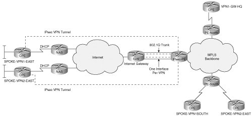
If an IPSec tunnel needs to terminate on a unique IP address per VPN on the aggregation PE router, a unique interface or sub-interface is needed in the FVRF. These can be either unique VLANs, ATM PVCs, or Frame Relay sub-interfaces on the same router. The primary motivation for a unique IP address per VPN for IPSec termination is for cases in which the IPSec spokes use Main Mode with pre-shared key authentication and are assigned IP addresses dynamically on the WAN interface. In this case, match identity based on IP address does not work; it is not known what the tunnel endpoint address will be. This is an inherent limitation of the IPSec protocol itself. To overcome the issue, a unique IP address and unique VRF is assigned per VPN customer.
Figure 9-5 illustrates this scenario and Example 9-24 shows the configuration of the aggregation PE.
Example 9-24. Configuration on VPN-GW1-EAST Terminating each VPN on a Unique Interface to Support Wild Card Keys
vpn-gw1-east#show running-config
hostname vpn-gw1-east
!
ip vrf vpn1
 rd 200:1
 route-target export 200:1
 route-target import 200:1
!
ip vrf vpn2
 rd 201:1
 route-target export 201:1
 route-target import 201:1
!
crypto keyring vpn1 vrf vpn1
  pre-shared-key address 0.0.0.0 key vpn1aes
crypto keyring vpn2 vrf vpn2
  pre-shared-key address 0.0.0.0 key vpn2ikev2
!
crypto isakmp policy 1
 authentication pre-share
 group 2
!
crypto isakmp keepalive 10 10
!
crypto isakmp profile vpn1
vrf vpn1 description IVRF
keyring vpn1
match identity address 0.0.0.0 0.0.0.0 vrf vpn1
!
crypto isakmp profile vpn2
vrf vpn2 description IVRF
keyring vpn2
match identity address 0.0.0.0 0.0.0.0 vrf vpn2
!
crypto ipsec transform-set vpn1 esp-3des esp-sha-hmac
crypto ipsec transform-set vpn2 esp-3des esp-md5-hmac
!
!
interface Loopback0
 ip address 9.2.1.100 255.255.255.255
!
interface FastEthernet0/0.1
 description FVRF
 encapsulation dot1q 100
 ip vrf forwarding vpn1
 ip address 9.1.1.35 255.255.255.252
 duplex full
 random-detect
 crypto map vpn1
!
interface FastEthernet0/0.2
 description FVRF
 encapsulation dot1q 101
 ip vrf forwarding vpn1
 ip address 9.1.1.37 255.255.255.252
 duplex full
 random-detect
 crypto map vpn2
!
interface FastEthernet2/0
 ip address 100.1.1.147 255.255.255.0
 duplex full
!
interface FastEthernet4/0
 ip address 9.2.1.1 255.255.255.252
 duplex full
 tag-switching ip
!
ip route vrf vpn1 0.0.0.0 0.0.0.0 9.1.1.36
ip route vrf vpn2 0.0.0.0 0.0.0.0 9.1.1.38
!
access-list 100 permit ip 10.0.1.0 0.0.0.255 any
access-list 101 permit ip 10.0.1.0 0.0.0.255 any
IPSec CPE and VPN clients for customers VPN1 and VPN2 are configured with two different tunnel endpoint addresses of the gateway, which in this case are 9.1.1.35 and 9.1.1.37, respectively. It is important to note that you should have a default route per VRF and the router that front ends the PE on FastEthernet 0/0 should also be configured with 802.1q-encapsulated sub-interfaces.
This section looks at some common deployment scenarios for the network-based VPN solution:
IPSec to MPLS VPN over GRE
IPSec to Layer 2 VPN
PE-PE encryption
The most common application for the network-based VPN solution is to extend the MPLS VPN service provider footprint over the Internet. You learned the operation of this scenario in the previous section. You also learned from previous chapters that dynamic routing is desirable for site-to-site VPNs. Because an MPLS VPN provides dynamic routing capabilities, it would be very desirable to extend the dynamic routing capabilities to the extended sites over IPSec. The need for dynamic routing forces the use of IPSec over GRE. Figure 9-6 shows the topology that we use to describe this deployment model.
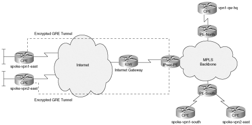
SPOKE-VPN2-EAST is the spoke that will have a GRE tunnel protected by IPSec to VPN-GW1- EAST. EIGRP is the routing protocol between the hub and spoke. At the hub that is also the MPLS VPN PE, one could redistribute the spoke routes into MP-BGP and advertise it to remote PEs.
Similarly, routes from remote PEs can be advertised to the spoke by redistributing into EIGRP from MP-BGP. Example 9-25 shows the configuration of the hub.
Example 9-25. Configuration on VPN-GW1-EAST Terminating GRE Tunnels into a VRF
vpn-gw1-east#show running-config

!
hostname vpn-gw1-east
!

!
!
ip vrf vpn1
 rd 200:1
 route-target export 200:1
 route-target import 200:1
!
ip vrf vpn2
 rd 201:1
 route-target export 201:1
 route-target import 201:1
!
ip cef
mpls label protocol ldp
tag-switching ip default-route
!
crypto keyring vpn1
  pre-shared-key address 9.1.1.146 key vpn1aes
crypto keyring vpn2
  pre-shared-key address 9.1.1.150 key vpn2ikev2
!
crypto isakmp policy 1
 authentication pre-share
 group 2
crypto isakmp keepalive 10 10
crypto isakmp profile vpn2
   keyring vpn2
   match identity address 9.1.1.150 255.255.255.255
!
!
crypto ipsec transform-set vpn1 esp-3des esp-sha-hmac
crypto ipsec transform-set vpn2 esp-3des esp-md5-hmac
 mode transport
!
crypto ipsec profile tunnel
 set transform-set vpn2
!
!

interface Tunnel0
 ip vrf forwarding vpn2
 ip address 10.2.1.1 255.255.255.0
 tunnel source 9.1.1.35
 tunnel destination 9.1.1.150
 tunnel protection ipsec profile tunnel
!
interface Loopback0
 ip address 9.2.1.100 255.255.255.255
!
interface FastEthernet0/0
 ip address 9.1.1.35 255.255.255.248
 duplex full
 crypto map vpn
!
interface FastEthernet2/0
 ip address 100.1.1.147 255.255.255.0
 duplex full
!
interface FastEthernet4/0
 ip address 9.2.1.1 255.255.255.252
 duplex full
 tag-switching ip
!
router eigrp 1
 auto-summary
 !
 address-family ipv4 vrf vpn2
 redistribute bgp 1001 metric 10000 100 255 1 1500
 network 10.2.1.0 0.0.0.255
 auto-summary
 autonomous-system 1
 exit-address-family
!
router ospf 1
 log-adjacency-changes
 redistribute static subnets
 network 9.2.1.0 0.0.0.3 area 0
 network 9.2.1.100 0.0.0.0 area 0
!
router bgp 1001
 no synchronization
 bgp log-neighbor-changes
 neighbor 153.1.1.1 remote-as 1001
 neighbor 153.1.1.1 update-source Loopback0
 no auto-summary
 !
 address-family vpnv4
 neighbor 153.1.1.1 activate
 neighbor 153.1.1.1 send-community extended
 exit-address-family
 !
 address-family ipv4 vrf vpn2
 redistribute connected
 redistribute static
 redistribute eigrp 1
 no auto-summary
 no synchronization
 exit-address-family
 !
 address-family ipv4 vrf vpn1
 redistribute connected
 redistribute static
 no auto-summary
 no synchronization
 exit-address-family
!
ip local pool vpn1pool 192.168.1.1 192.168.1.100 group vpn1group
ip classless
ip route 0.0.0.0 0.0.0.0 9.1.1.33
no ip http server
no ip http secure-server
!
end
The key part of the configuration is that the GRE tunnel is configured to be in a VRF. Once the IPSec packet gets decrypted, it is handed over to the GRE tunnel and, as the GRE tunnel is in a VRF, the IP packet flows are mapped into the appropriate VRF.
The IPSec GRE scenario can be extended to use DMVPN, an option that is explored in this section. In Chapter 7, “Auto-Configuration Architectures for Site-to-Site IPSec VPNs,” you learned how Dynamic Multipoint VPN (DMVPN) drastically reduces configuration complexity at the hub for a hub-and-spoke VPN. DMVPN can be used to scale the configuration of the PE in the network-based solution. Each VPN in this solution requires a unique mGRE interface terminated in a VRF. Figure 9-7 shows this scenario and Example 9-26 represents a typical configuration on the PE.
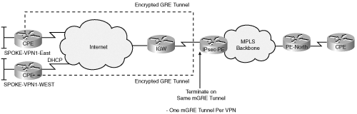
Example 9-26. DMVPN Configuration on VPN-GW1-EAST Mapped to VRFs
vpn-gw1-east#show running-config
version 12.3
service timestamps debug datetime
service timestamps log datetime msec
no service password-encryption
!
hostname vpn-gw1-east
!
ip vrf vpn1
 rd 200:1
!
ip vrf vpn2
 rd 201:1
!
ip cef
mpls label protocol ldp
tag-switching ip default-route
no ftp-server write-enable
!
crypto keyring vpn1
  pre-shared-key address 9.1.1.146 key vpn1aes
crypto keyring vpn2
  pre-shared-key address 9.1.1.150 key vpn2ikev2
!
crypto isakmp policy 1
 authentication pre-share
 group 2
crypto isakmp keepalive 10 10
!
crypto ipsec transform-set dmvpn esp-3des esp-md5-hmac
 mode transport
!
crypto ipsec profile tunnel
 set transform-set dmvpn
!
!
interface Tunnel0
 ip vrf forwarding vpn1
 ip address 10.2.1.1 255.255.255.0
 ip mtu 1400
 ip nhrp authentication coke
 ip nhrp map multicast dynamic
 ip nhrp network-id 100
 ip nhrp holdtime 600
 no ip split-horizon eigrp 1
 tunnel source Loopback0
 tunnel key 100
 tunnel protection ipsec profile tunnel shared

!
interface Tunnel1
ip vrf forwarding vpn2
 ip address 10.3.1.1 255.255.255.0
 ip mtu 1430
 ip nhrp authentication vpn2
 ip nhrp map multicast multicast
 ip nhrp network-id 101
 ip nhrp holdtime 600
  no ip split-horizon eigrp 1
 ip nhrp nhs 10.1.1.1
tunnel source Loopback0
 tunnel key 101
 tunnel protection ipsec profile tunnel shared

interface Loopback0
 ip address 9.2.1.100 255.255.255.255
!
interface FastEthernet0/0
 ip address 9.1.1.35 255.255.255.248
 duplex full
!
interface FastEthernet2/0
 ip address 100.1.1.147 255.255.255.0
 duplex full
!
interface FastEthernet4/0
ip address 9.2.1.1 255.255.255.0
duplex full
mpls-ip
!
router eigrp 1
 auto-summary
 !
 address-family ipv4 vrf vpn2
 redistribute static
 redistribute connected
 network 10.3.1.0 0.0.0.255
 auto-summary
 autonomous-system 1
 exit-address-family
!
address-family ipv4 vrf vpn1
 redistribute static
 redistribute connected
 network 10.2.1.0 0.0.0.255
 auto-summary
 autonomous-system 1
 exit-address-family
!
ip route 0.0.0.0 0.0.0.0 9.1.1.33
no ip http server
no ip http secure-server
!
In the configuration example shown in Example 9-26, the tunnel addresses used by the tunnels are on unique subnets for the sake of clarity. The subnets used on the mGRE tunnels for each VRF can be overlapping if so desired. One last statement with respect to the configuration is that if both tunnels are sharing the same IPSec profiles, they can be unique per tunnel if desired.
This scenario is similar to mapping a site into an MPLS VPN over IPSec, except that in this case, the traffic after decryption at the PE is mapped into an outbound interface that is also in a VRF.
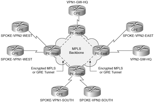
This scenario is useful for a Layer 2 provider (such as an ATM or Frame-Relay provider) to extend their footprint. The provider could terminate CPEs and remote access clients via IPSec to a PE at the edge of their cloud and map them to appropriate customer VRFs. Each of these VRFs is also mapped to the corresponding VPN customer’s L2 Virtual Circuit (Ethernet VLAN, ATM, or Frame Relay VC). The IPSec packets coming in through the Internet are decrypted and mapped to the right VRF; once they are in the VRF, a route lookup is done before they are sent out through the right L2 Virtual Circuit. Figure 9-8 shows this scenario and Example 9-27 shows the configuration for this scenario.

Example 9-27. Configuration on VPN-GW1-EAST Showing Termination of an IPSec Session and Mapping Them to Routed ATM Interfaces
vpn-gw1-east#show running-config
version 12.3
service timestamps debug datetime
service timestamps log datetime msec
no service password-encryption
!
hostname vpn-gw1-east
aaa new-model
!
aaa authentication login vpn group radius
aaa authorization network vpn group radius
aaa accounting update periodic 5
aaa accounting network vpn start-stop group radius
aaa session-id common
ip subnet-zero
!
!
ip vrf vpn1
 rd 200:1
!
ip vrf vpn2
 rd 201:1
!
ip cef
mpls label protocol ldp
tag-switching ip default-route
no ftp-server write-enable
!
crypto keyring vpn1
  pre-shared-key address 9.1.1.146 key vpn1aes
crypto keyring vpn2
  pre-shared-key address 9.1.1.150 key vpn2ikev2
!
crypto isakmp policy 1
 authentication pre-share
 group 2
crypto isakmp keepalive 10 10
crypto isakmp profile vpn1
   vrf vpn1
   keyring vpn1
   match identity address 9.1.1.146 255.255.255.255
crypto isakmp profile vpn1-ra
   vrf vpn1
   match identity group vpn1group
   client authentication list vpn
   isakmp authorization list vpn
   client configuration address respond
   accounting vpn
crypto isakmp profile vpn2
   vrf vpn2
   keyring vpn2
   match identity address 9.1.1.150 255.255.255.255
!
!
crypto ipsec transform-set vpn1 esp-3des esp-sha-hmac
crypto ipsec transform-set vpn2 esp-3des esp-md5-hmac
 mode transport
!

!
!
crypto dynamic-map dynamic 1
 set transform-set vpn1
 set isakmp-profile vpn1-ra
 reverse-route remote-peer 9.1.1.33
!
!
crypto map vpn 1 ipsec-isakmp
set peer 9.1.1.146
set transform-set vpn1
set isakmp-profile vpn1
reverse-route remote-peer address 9.1.1.33
match address 101
crypto map vpn 2 ipsec-isakmp
set peer 9.1.1.150
set transform-set vpn2
set isakmp-profile vpn2
reverse-route remote-peer address 9.1.1.33
match address 102

crypto map vpn 3 ipsec-isakmp dynamic dynamic
!
interface FastEthernet0/0
 ip address 9.1.1.35 255.255.255.248
 duplex full
 crypto map vpn
!
interface FastEthernet2/0
 ip address 100.1.1.147 255.255.255.0
 duplex full
!
interface ATM 4/0
 no ip address
interface ATM4/0.1
 ip address 9.2.1.1 255.255.255.252
 ip vrf forwarding vpn1
 pvc 0/101
 encapsulation aal5snap
 broadcast
interface ATM4/0.2
ip address 9.2.1.1 255.255.255.252
ip vrf forwarding vpn2
pvc 0/102
encapsulation aal5snap
broadcast
!
router eigrp 1
 auto-summary
 !
 address-family ipv4 vrf vpn2
 redistribute static
 network 9.2.1.0 0.0.0.255
 auto-summary
 autonomous-system 1
 exit-address-family
!
address-family ipv4 vrf vpn1
 redistribute static
 network 9.2.1.0 0.0.0.255
 auto-summary
 autonomous-system 1
 exit-address-family


ip local pool vpn1pool 192.168.1.1 192.168.1.100 group vpn1group
ip classless
ip route 0.0.0.0 0.0.0.0 9.1.1.33
no ip http server
no ip http secure-server
!
radius-server host 100.1.1.4 auth-port 1645 acct-port 1646
radius-server key cisco
radius-server vsa send accounting
!
end
In this example, all traffic from the remote CE is decrypted and mapped into the ATM sub-interface of the appropriate VPN.
One of the primary requirements for a VPN service is security. Traditional CE-based IPSec VPNs offer data security by encrypting data from CE-CE. For an MPLS VPN, the security comes from the separation of routing contexts (VRFs) at the PE. Of course, one could have an IPSec overlay of CEs over an MPLS VPN to provide data encryption, which means that every CE on that VPN has to build a full mesh of encrypted tunnels to every other CPE on that VPN over the provider’s backbone. The overlay model defeats the scalability and any-to-any optimal routing of MPLS VPNs.
The primary driver for providers to encrypt PE-PE traffic is to extend MPLS VPN (RFC 2547bis) service across IP backbones that they have no control over (for example, the Internet). Also, this solution provides end-to-end encryption CE to PE, PE to PE, and PE to CE. Figure 9-9 shows the PE-PE encryption scenario.
One of the requirements used for PE-PE encryption is to build an MPLS-in-GRE packet between the PEs and encrypt the GRE-encapsulated packet using IPSec.
Note
The IETF MPLS VPN service using GRE is very well documented in the IETF draft [draft-ietf-l3vpn-gre-ip-2547-03.txt].
The deployment technique shown here for PE-PE encryption is to run LDP and MP-BGP over the GRE tunnel. One could also run MP-BGP outside the GRE tunnel and set the next_hop for the vpn prefixes via the GRE tunnel. Note that the use of GRE point-to-point tunnels for any-to-any PE-PE encryption requires a full mesh of GRE tunnels between the PEs. Example 9-28 shows the configuration for PE-PE encrypted GRE tunnel running MPLS VPNs.
Example 9-28. Configuration on VPN-GW1-EAST Showing PE-PE Encryption
vpn-gw1-east#show running-config

hostname vpn-gw1-east
!
ip vrf vpn1
 rd 200:1
 route-target export 200:1
 route-target import 200:1
!
ip vrf vpn2
 rd 201:1
 route-target export 201:1
 route-target import 201:1
!
mpls label protocol ldp
tag-switching tdp router-id Loopback0
tag-switching ip default-route
!
crypto keyring vpn1
  pre-shared-key address 9.1.1.145 key vpn1aes
crypto keyring vpn2
  pre-shared-key address 9.1.1.149 key vpn2ikev2
!
crypto isakmp policy 1
 authentication pre-share
 group 2
!
crypto isakmp keepalive 10 10
!
crypto isakmp profile vpn1
 vrf vpn1 description IVRF
 keyring vpn1
 match identity address 9.1.1.145 255.255.255.255
 accounting vpn
!
crypto isakmp profile vpn1-ra
  vrf vpn1
  match identity group vpn1group
  client authentication list vpn
  isakmp authorization list vpn
  client configuration address respond
  accounting vpn
!
crypto isakmp profile vpn2
 vrf vpn2
 keyring vpn2
 match identity address 9.1.1.149 255.255.255.255
 accounting vpn
!
crypto ipsec transform-set vpn1 esp-3des esp-sha-hmac
crypto ipsec transform-set vpn2 esp-3des esp-md5-hmac
!
crypto dynamic-map dynamic 1
 set transform-set vpn1
 set isakmp-profile vpn1-ra
 reverse-route remote-peer 9.1.1.33
!
crypto map vpn 1 ipsec-isakmp
set peer 9.1.1.146
set transform-set vpn1
set isakmp-profile vpn1
reverse-route remote-peer address 9.1.1.33
match address 101
crypto map vpn 2 ipsec-isakmp
set peer 9.1.1.150
set transform-set vpn2
set isakmp-profile vpn2
reverse-route remote-peer address 9.1.1.33
match address 102
crypto map vpn 3 ipsec-isakmp dynamic dynamic
!
interface Tunnel0
 ip address 100.1.1.1 255.255.255.252
 tunnel source 9.2.1.100
 tunnel destination 9.2.1.101
 mpls-ip
 tunnel protection ipsec profile tunnel
!
interface Loopback0
 ip address 9.2.1.100 255.255.255.255
!
interface FastEthernet0/0
 description FVRF
 ip address 9.1.1.35 255.255.255.248
 duplex full
 random-detect
 crypto map vpn
!
interface FastEthernet2/0
 ip address 100.1.1.147 255.255.255.0
 duplex full
!
interface FastEthernet4/0
 ip address 9.2.1.1 255.255.255.252
 duplex full
!
router ospf 1
 log-adjacency-changes
 network 9.2.1.0 0.0.0.3 area 0
!
router bgp 1001
 no synchronization
 bgp log-neighbor-changes
 neighbor 100.100.1.2 remote-as 1001
 neighbor 100.100.1.2 update-source tunnel0
 no auto-summary
 !
 address-family vpnv4
 neighbor 100.100.100.2 activate
 neighbor 100.100.100.2 send-community extended
 exit-address-family
 !
 address-family ipv4 vrf vpn2
 redistribute connected
 redistribute static
 no auto-summary
 no synchronization
 exit-address-family
 !
 address-family ipv4 vrf vpn1
 redistribute connected
 redistribute static
 no auto-summary
 no synchronization
 exit-address-family
!
ip route 0.0.0.0 0.0.0.0 9.1.1.33 (default route to the Internet)
ip route 153.1.1.1 255.255.255.255 Tunnel0
!
access-list 100 permit ip 10.0.1.0 0.0.0.255 any
access-list 101 permit ip 10.0.1.0 0.0.0.255 any

vpn-gw1-east#show ip route vrf vpn1

Routing Table: vpn1
Codes: C - connected, S - static, R - RIP, M - mobile, B - BGP
       D - EIGRP, EX - EIGRP external, O - OSPF, IA - OSPF inter area
       N1 - OSPF NSSA external type 1, N2 - OSPF NSSA external type 2
       E1 - OSPF external type 1, E2 - OSPF external type 2
      i - IS-IS, su - IS-IS summary, L1 - IS-IS level-1, L2 - IS-IS level-2 S- static
  route

Gateway of last resort is not set

     9.0.0.0/32 is subnetted, 1 subnets
S       9.1.1.146 [1/0] via 9.1.1.33
     10.0.0.0/24 is subnetted, 2 subnets
B       10.1.1.0 [200/0] via 100.100.100.2, 00:23:17
S       10.0.68.0 [1/0] via 9.1.1.146

vpn-gw1-east#show mpls ldp nei
    Peer LDP Ident: 153.1.1.1:0; Local LDP Ident 9.2.1.100:0
        TCP connection: 153.1.1.1.11056 - 9.2.1.100.646
        State: Oper; Msgs sent/rcvd: 785/783; Downstream
        Up time: 00:25:33
        LDP discovery sources:
          Tunnel1, Src IP addr: 100.100.100.2
        Addresses bound to peer LDP Ident:
          153.1.1.1       163.1.1.1       100.100.100.2

vpn-gw1-east#show ip bgp vpn vrf vpn1
BGP table version is 51, local router ID is 9.2.1.100
Status codes: s suppressed, d damped, h history, * valid, > best, i - internal,
              r RIB-failure, S Stale
Origin codes: i - IGP, e - EGP, ? - incomplete

   Network          Next Hop            Metric LocPrf Weight Path
Route Distinguisher: 200:1 (default for vrf vpn1)
*  9.1.1.146/32     9.1.1.33                 0         32768 ?
*> 10.0.68.0/24     9.1.1.146                0         32768 ?
*>i10.1.1.0/24      100.100.100.2            0    100      0 ?
* i                 153.1.1.1                0    100      0 ?

vpn-gw1-east#show ip cef vrf vpn1
10.1.1.0/24, version 20, epoch 0
0 packets, 0 bytes
  tag information set
    local tag: VPN-route-head
    fast tag rewrite with Tu1, point2point, tags imposed: {498}
  via 100.100.100.2, 0 dependencies, recursive
    next hop 100.100.100.2, Tunnel1 via 100.100.100.0/24
    valid adjacency
    tag rewrite with Tu1, point2point, tags imposed: {498}
From the different outputs, you can see that the next hop for the BGP learned routes in the routing table for each of the VRFs and the LDP neighbor on VPN-GW1-EAST is learned via the tunnel. The forwarding information for the VRF VPN1 learned routes point toward the far-end PE tunnel IP address (100.100.100.2) with the appropriate VPN label (498).
The downside to PE-PE encryption is that PE-CE data is still in the clear. Of course, one could also encrypt data on the PE-CE link in addition to PE-PE encryption. But, then the PE has to do much more work. It has to decrypt data from the CE-PE and re-encrypt the data for the PE-PE.
In this chapter, you reviewed a new type of VPN service known as network-based VPNs, which allow service providers to offer value-added services. The most common application for network-based VPNs is for MPLS VPN providers to extend their footprint to sites where they have no direct connectivity to the CEs. You reviewed various connection methods with which remote sites used IPSec to reach a network-based VPN. The various connection options (that is, IPSec, EzVPN, IPSec over GRE, and DMVPN) each provide unique capabilities and constraints. Service providers may offer a combination of these IPSec access methods based on the requirements of the customer’s CE site or remote access client. The customer may choose the IPSec access protocol that best meets the needs of the VPN.
The service provider’s value in providing IPSec access to network-based VPNs is to assume the role of traffic management and capacity planning. The PE effectively plays the role of the enterprise “hub” VPN gateway, but does so in a distributed manner. The provider is now responsible for managing the scalability and performance of the enterprise IPSec “hub,” using the same principles described in the previous chapters. The enterprise is also able to leverage the provider’s investment in redundant infrastructure. Likewise, the enterprise achieves any-to-any data paths between CE sites without having to invest in expensive CE equipment capable of building a full mesh of IPSec tunnels.
The primary drawback to the network-based VPN is that customer traffic is decrypted at the PE. The network-based VPN does require more coordination between the enterprise and provider with regards to ensuring that packet QoS attributes are treated appropriately and routing updates are processed appropriately. Despite the fact that traffic segregation is retained at the PE, many customers require encryption from CE to CE. CE to CE encryption requires a per-peer relationship. Running end-to-end encryption between the CE devices through the MPLS VPN negates many of the advantages of the MPLS VPN. Most significant losses are the any-to-any data connectivity, the optimized provisioning with O(1) changes per site, and the scalable routing relationships. These are significant trade-offs that network designers must consider when building a network-based VPN. The decision to use end-to-end IPSec or CE-PE IPSec in the context of a network-based VPN will be determined by taking into account security risks and potential threats.