Recommended Hardware Configuration
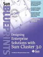
The company decided to implement a two-node Sun Cluster solution using the Sun Fire midframe server and Sun StorEdge arrays (FIGURE 6-6). The following sections describe the hardware features the Company considered in making this decision
Figure 6-6. Sun Cluster Configuration
Management Server
The management server described in Chapter 4 provides a single management point for the cluster. Many of the functions of the management server are available in other infrastructures. The ITO identified the functions that are critical to direct management or recovery of the cluster. The management server is ready to support the cluster when needed. The management server is not used to support the critical services of other systems. The functions served by the management server and those served by other infrastructure servers are these:
Sun Management Center server
JumpStart service for the cluster nodes
Network Time Protocol (NTP)
Consolidated system log messages archive (not to be confused with Oracle logs)
Optionally, the Company can put the management server in a separate cabinet. However, the ITO currently believes that keeping the management server located with the cluster hardware helps avoid confusion.
Nodes
The Company has chosen to implement a medium-sized cluster, using Sun Fire™ 4800 mid-range servers for the nodes. However, a larger mid-range server, the Sun Fire™ 6800 server, is available from Sun. This server shares many of its components with the Sun Fire 4800 server. The Sun Fire 6800 server provides an upgrade option in case the Company requires more computing or I/O capabilities in the future and the current servers are full
Options
The Sun Fire 4800 server is based on UltraSPARC III technology. This server, which was based on the UltraSPARC II technology, replaces the popular Sun Enterprise™ 4500 server in the Sun product portfolio. The key configuration options are
One to three system boards containing two or four processors, each with up to 32 Gbytes of main memory
Two to twelve CPUs in two CPU increments
CPUs run at 750 MHz or 900 MHz
2 to 96 Gbytes of main memory
One or two system controllers that control the configuration of the platform and act as console devices
One or two hot-pluggable I/O assemblies that can contain either eight PCI or six cPCI slots
PCI assemblies containing eight slots assigned to four PCI buses. Two buses have one dedicated slot each. The other two buses each have three slots. Most slots accept full-length cards. However, there is a hardware component that limits two slots for short cards only.
cPCI assemblies contain six individually hot-pluggable slots assigned to four cPCI buses. Two buses have one dedicated slot each. The other two buses each have two slots.
Redundant Sun Fireplane™ interconnect switches
N+1 redundant, hot-pluggable power supplies; internal power is configured to share the load across all components in the chassis
Two redundant transfer units (RTUs), which provide automatic switching between dual power feeds. The RTUs supply AC power to the power supplies.
Redundant, hot-pluggable fan trays
The Sun Fireplane interconnect switches run at 150 MHz. Each port on this interconnect can transfer data at a rate of up to 9.6 Gbytes/sec. The CPU/memory boards transfer at 9.6 Gbytes/sec. I/O assemblies can only transfer data at 2.4 Gbytes/sec. A marketing claim of 33.6 Gbytes/sec (three at 9.6 plus two at 2.4 Gbytes/sec) is described as an “aggregate bandwidth.” Benchmarks have shown sustained rates of nearly 9.6 Gbytes/sec, which is far greater than the possible I/O bandwidth.
The UltraSPARC III processor ranges in speed from 600 to 900 MHz in 150 MHz increments to match the Sun Fireplane interconnect speed. Further speed enhancements are planned. The UltraSPARC III has sophisticated cache-coherency (synchronization) circuitry built into the processor. The UltraSPARC III design was intended to reduce the latency between the processor and main memory, including the cache-coherency steps, for hundreds of processors running a single Solaris operating environment instance. The cache coherency uses both a snooping protocol and a distributed directory-based protocol.
In the snooping protocol, all processors look at, or snoop, on the address bus to see what cache transactions are occurring. The problem with snooping protocols is that the benefits for all processors seeing all address bus transactions is difficult to scale to large numbers of processors without compromising latency.
In the distributed directory-based protocol, each processor contains a list of the processors that have cached data. This list avoids the requirement of all processors seeing all transactions by adding a directory lookup to each processor's local directory. This potentially adds latency, depending on whether the cached data is local or remote, but this additional latency scales better for larger systems. Sun Fire servers use both techniques—snooping protocols on processor boards containing up to four processors, and distributed directory-based protocols between boards. As previously described, the Oracle 9i RAC implemented a similar directory-based method for caching between cluster nodes.
Full hardware redundancy is designed into the Sun Fire 4800 server. Components such as system clocks, system controllers, power, and cooling are fully redundant. The Sun Fireplane interconnect can be configured redundantly, too. All data paths use end-to-end ECC error protection. In addition, fault isolation is improved over the previous generation of servers so that faults can be isolated to the FRU that has faulted. A variety of advanced mainframe-class features, such automatic system recovery (ASR), hot CPU upgrades, and dynamic reconfiguration deliver exceptional serviceability.
ASR occurs when the system is powered on. Optionally, ASR can occur when the system reboots after a hardware error is found. The additional end-to-end ECC and other enhanced fault isolation features combine with ASR. These features are a significant improvement over the previous generation of Sun Enterprise servers. Faulty components are blacklisted, similar to the blacklist feature in the Sun Enterprise 10000 server. Hot CPU upgrades allow upgrades to faster CPUs while the Solaris operating environment and applications continue to be available. Dynamic reconfiguration enables you to add or remove system hardware resources (CPUs, memory modules, and I/O controllers) without shutting down the Solaris operating environment or powering down the system.
For proper operation, the dynamic system domain features in a Sun Cluster environment require special design and processes. For more information, contact a Sun Service provider.
With Solaris processor sets, Solaris Resource Manager software, and dynamic system domain features, the system has the flexibility to accommodate changing resource requirements across multiple applications.
The Sun Fire 4800 server can be used as a deskside system, placed in a Sun Fire cabinet, or mounted in an industry-standard 19-inch rack.
A stated previously, the Company decided to purchase a pair of Sun Fire 4800 servers for use as nodes in the Oracle 9i RAC database cluster. TABLE 6-4 lists the node parts.
| Description | Quantity |
|---|---|
| Sun Fire cabinet | 1 |
| Sun Fire 4800 Server base package—factory-racked | 1 |
| PCI I/O assembly for Sun Fire 4800 Server | 2 |
| CPU/memory board with four 900 MHz CPU, 32-MB ECache, 4 x 2 Gbyte memory | 2 |
| Sun Enterprise power cord, U.S. version | 4 |
| Optional RTS AC Module for Sun Fire Server | 1 |
| Redundancy Kit for Sun Fire 4800 Server (includes one power supply, one fan tray, and one system controller) | 1 |
| Media tray with two 36-Gbyte disks and one DVD | 1 |
| Media tray with two 36-Gbyte disks and one DDS4 tape drive | 1 |
| SunSwift™ UltraSCSI and SunFastEthernet adapter | 4 |
| Sun StorEdge PCI single FC network adapter | 4 |
| Gigabit Ethernet PCI adapter 2.0 | 5 |
TABLE 6-5 lists the node I/O configuration.
| I/O Bay | PCI Slot | PCI Controller/ Bus | Card | Connector | Target |
|---|---|---|---|---|---|
| IB 8 | 0 (short) | 0, B | 1032A: PCI UltraSCSI and SunFastEthernet adapter | HD68, SCSI | D240 No.1, left bus |
| RJ-45, SunFastEthernet | Cluster administration network switch | ||||
| 1 (short) | 0, B | 6799A: PCI FC-AL network adapter | SC, FC-AL | FC-AL switch No.1 | |
| 2 | 0, B | Unused | |||
| 3 | 0, A | 1141A: PCI Gigabit Ethernet NIC (MMF) | SC, Gigabit Ethernet | Cluster interconnect No.1 | |
| 4 | 1, B | Unused | |||
| 5 | 1, B | 1032A: PCI UltraSCSI and SunFastEthernet adapter | HD68, SCSI | D240 No.2, left bus | |
| RJ-45, SunFastEthernet | No connection | ||||
| 6 | 1, B | 6799A: PCI FC-AL network adapter | SC, FC-AL | FC-AL switch No.3 | |
| 7 | 1, A | 1141A: PCI Gigabit Ethernet NIC (MMF) | SC, Gigabit Ethernet | Public network switch No.1 | |
| IB 6 | 0 (short) | 0, B | 1032A: PCI UltraSCSI and SunFastEthernet adapter | HD68, SCSI | D240 No.1, right bus |
| RJ-45, SunFastEthernet | No connection | ||||
| 1 (short) | 0, B | 6799A: PCI FC-AL network adapter | SC, FC-AL | FC-AL switch No.2 | |
| 2 | 0, B | Unused | |||
| 3 | 0, A | 1141A: PCI Gigabit Ethernet NIC (MMF) | SC, Gigabit Ethernet | Cluster interconnect No.2 | |
| 4 | 1, B | 1032A: PCI UltraSCSI and SunFastEthernet adapter | HD68, SCSI | D240 No.2, right bus | |
| RJ-45, SunFastEthernet | No connection | ||||
| 5 | 1, B | 1141A: PCI Gigabit Ethernet NIC (MMF) | SC, Gigabit Ethernet | Backup network switch |
Options Considered But Discounted
The Sun Fire 4800 server is available in a deskside configuration. However, deskside configurations are not suitable for data center environments, where rackmounted servers are preferred. Exposed cables are a problem with deskside or desktop systems. It is very difficult to secure the cables and ensure that they are properly maintained. For example, the minimum cable bend radius can be violated if the cable cannot be secured to ensure that the bends are within tolerance. Exposed cabling increases the probability that cables can be accidentally damaged. Also, it is difficult to secure a collection of deskside components in seismically active areas. It is better to place servers designed for highly available services in racks so the Company can control their mechanical configurations
Boot Environment
The boot environment uses Sun StorEdge™ D240 media trays. The Sun StorEdge D240 media tray is a compact, scalable, and highly flexible storage solution, specifically designed to support the Sun Fire servers for the boot disk and removable media solution. The slim, two-rack unit (2U), rackmounted configuration can accommodate a range of storage devices including removable hard disks, DVD-ROM, and tape backup.
The Sun StorEdge D240 media tray features a single or dual SCSI bus configuration that supports up to two independent server boot domains per system. Dual, hot-swappable, load-sharing power supplies power the media tray. FIGURE 6-7 shows the front view of the media tray.
Figure 6-7. Sun StorEdge D240 Media Tray—Front View

Electrically, the SCSI bus can be split into two, with one 3.5-inch disk and one 5.25- inch bay per bus (FIGURE 6-8). This provides containment for faults on the SCSI buses. The dual power supplies are load sharing and fully redundant. The FRUs are independently replaceable, so the Company can replace any active component without disrupting other active components. The Sun StorEdge D240 media tray can support two independent SCSI buses without introducing opportunities for common mode faults.
Figure 6-8. Sun StorEdge D240 Media Tray—SCSI Bus Configurations
The ITO has a policy that all boot devices on production servers must be mirrored to improve availability. In addition, an upgrade procedure with rollback capability must be designed into the boot environment. This allows the Company to install patches or add new versions of the software stored on the boot disks without risking the existing operational environment. When feasible, the Company can use a separate disk for the upgrade procedure, to help ensure fault containment if a problem occurs during patch installation or upgrades. Solaris Live!™ Upgrade software is used to manage the boot environments. FIGURE 6-9 shows the boot disk layout selected for each node in the cluster.
Figure 6-9. Production Server Boot Disk Environment

Fault tree analysis (FTA) and Event Tree Analysis (ETA) (see Appendix D) of this design show that there is a potential risk in the case of multiple failures. If the primary boot drive or the SCSI bus serving the primary boot disk fails, the system activates the hot spare. This puts the new primary boot disk and boot mirror on the same SCSI bus. During the time required to service the first failure, the configuration is vulnerable to a second failure on the second SCSI bus. This vulnerability exists only for the time required to repair the first failure, which reinforces the importance of repairing failures quickly and maintaining low MTTR rates. FIGURE 6-10 shows this failure scenario.
Figure 6-10. Multiple Failure Scenario

An alternate design using the split bus capability of the Sun StorEdge D240 coupled with two SCSI controllers was considered. FIGURE 6-11 shows this alternate design.
Figure 6-11. Alternate Design for Production Server Boot Disk Environment
The alternate design consumes more server I/O slots than the original design. A preferred solution would be to use a dual SCSI controller card. Sun currently sells both a single-ended (6540A) and differential (6541A) UltraSCSI card; however, these cards do not have firmware that would enable them to be used as boot disk controllers. Currently, a dual SCSI PCI controller with boot firmware is not available from Sun.
It is rare that you can consider such multiple failure scenarios owing to complexity. However, when the number of components is small and options exist to help build additional redundancy, the analysis can prove beneficial.
Shared Storage
The Company decided to use the Sun StorEdge T3 array as the shared storage for the cluster. TABLE 6-6 lists the required shared storage parts.
| Description | Quantity |
|---|---|
| 2620-Gbyte Sun StorEdge T3ES; includes eight T3 arrays configured in four partner groups in one 72-inch StorEdge Expansion cabinet, two eight-port FC switches with five GBICs each. | 1 |
| Power cords | 4 |
The key specifications of the Sun StorEdge T3 array are
Advanced architecture that uses full Fibre Channel connectivity, switched-loop design, and failover security
Path failover with mirrored cache with hot-swap and redundant RAID controllers, power supplies, cooling fans, backup batteries, interconnect cards, and drives
Modular flexibility combined with full, front-to-back fiber architecture allows configuration for high-transaction, high-bandwidth, or high-performance computing
Compatible with Jiro™ technology for storage network interoperability and manageability
Linear scalability to a massive 169 Tbytes on a single server
Multiple platform failover support on a variety of host servers and operating systems
Sun Remote Services (SRS) program support for continuous remote systems monitoring
The Sun StorEdge T3 array presents one or two logical unit numbers (LUNs) to a host. In the Solaris operating environment, LUNs are synonymous with single disks. Each LUN presents one disk in /dev/rdsk/c*t*d*s[0-7]. Each LUN can have a different RAID configuration. The Company can configure a disk in the array as a hot spare to improve MTTR in case of a disk failure in a data-protected LUN. LUN configurations can be created as follows:
RAID 1— Minimum of two disks regardless of whether a hot spare is used. Up to eight disks with a hot spare. Up to nine disks without hot spare.
RAID 5— Minimum of three disks (two data plus one parity). Up to eight disks (seven data plus one parity) with hot spare or nine disks (eight data plus one parity) without hot spare. Sun StorEdge T3 array hardware and firmware have been optimized for RAID 5. In most cases, RAID 5 outperforms RAID 1 or RAID 1+0.
RAID 0— Single LUN with up to nine disks. No hot spare is possible because RAID 0 does not offer data protection. Use of RAID 0 is advised only in conjunction with an external form of data protection, such as host-based mirroring across two Sun StorEdge T3 arrays, or in the rare case when host-based RAID 5 stripes across multiple trays is used. This configuration is not recommended for highly available systems, since the mean time between failure (MTBF) of a single LUN configuration is 1/9th that of a single disk. Also, since the mean time to recover (MTTR) includes synchronization of up to 657 Gbytes, using 73-Gbyte disks, and can be excessive. This combination of low MTBF and high MTTR is the direct opposite of the desired state in a highly available system.
For shared disks in Sun Cluster environments, the LUN is the unit of control by the logical volume managers. For data services in which a shared nothing data model is used (every service except Oracle 8i OPS or Oracle 9i RAC), only one node can access the LUN at a time. You should consider this limitation in the design of systems in which the number of available LUNs in the Sun StorEdge T3 array limits the number of resource groups that can be implemented.
The modular architecture used in the Sun StorEdge T3 array allows either single or dual controller configurations. The single controller configuration has several SPOFs and only clusters with host-based mirroring supported it. The dual controller configuration, also called partner pair, provides full redundancy. TABLE 6-7 summarizes several other implications of using the Sun StorEdge T3 array in clusters.
| Configuration | Analysis | |
|---|---|---|
| Single controller | Pro: | Best performance because the controllers do not have to synchronize their caches. |
| Con: | Many SPOFs. Requires host-based mirroring. May have high MTTR because of host-based mirror synchronization. | |
| Dual controller (partner pair) | Pro: | Fully redundant configuration. Cache is mirrored between controllers. Redundant paths to disks are used. |
| Con: | Mirrored cache synchronization has small impact on write performance. | |
| Con: | Controller boot time is nearly doubled because the master controller boots before the alternate controller. |
Note
In the case of a failure, host-based mirroring across single Sun StorEdge T3 array controllers can take a long time to synchronize, thus increasing the MTTR of such configurations. Configuring the LUNs as RAID 1 or RAID 5 with a hot spare can significantly reduce the MTTR when a single disk fails.
Options
The Sun StorEdge T3 array system designed by the Company can be easily expanded over time. Disks can be upgraded as newer, denser, or faster disks become available. More s can be added modularly to expand storage capacity or performance as required.
Options Considered But Discounted
Systems designers who need higher performance, minimized planned downtime, and higher availability should use Sun StorEdge T3 array single bricks that use host-based mirroring. Designers who need controller failover capabilities and better space utilization with hardware RAID 5 should use Sun StorEdge T3 array partner pair configurations.
Currently, the Sun StorEdge T3 array in the partner pair configuration can take as long as six minutes (worst case) to boot.
The Sun Cluster 3.0 software includes a cluster file system (CFS) that can be used instead of VxVM for Oracle 9i RAC clusters. However, Oracle 9i RAC does not currently support the CFS.
The Sun StorEdge T3 array is available in a desktop configuration. As discussed previously, it is better to place highly available systems in racks so you can control the mechanical configuration.
Network Interconnects
Network interconnects, also called private networks, are connections between cluster nodes used for internode cluster-related traffic. Public networks are network connections to other systems. This terminology can be confusing, especially when multiple public networks are being used. For example, backup networks, system administration networks, demilitarized zone (DMZ) networks, and user networks are all considered public networks from the Sun Cluster software perspective. Sun Cluster systems are not supported as gateways between networks.
Oracle 9i RAC is a service that depends on the performance of the cluster interconnect for scalability. DLM traffic (small packet) and data (large packet) traffic are sent over the interconnects. Sun Cluster 3.0 software supports a minimum of two and a maximum of six private cluster interconnects. All interconnects must be accessible by all nodes. Network switches are used for clusters with more than two nodes. The Sun Cluster software will multiplex its internode traffic across the cluster interconnects. This increases the bandwidth between the cluster nodes though it does not necessarily decrease latency between them.
Scalability in Oracle 9i RAC depends on the latency and bandwidth for the inter-node traffic. The Sun Cluster 3.0 software allows improvements mentioned previously to increase bandwidth. But the latency imposed by bandwidth, called the payload latency, is only one of the contributors to overall interconnect latency. The other contributors include length of cables, signalling technology, and overhead required for packets. Generally, the only way to reduce this latency is to change the interconnect technology. Currently, Sun Cluster 3.0 supports Sun Quad FastEthernet (100BASE-T) and Gigabit Ethernet FC-AL/P Combination Adapter (1000BASE-SX or 1000BASE-T) interconnects.
The Company uses separate backup, system administration, and user networks. The new system integrates seamlessly into the existing network structure. FIGURE 6-12 shows the cluster network design.
Figure 6-12. The Company's Network Design

Cache fusion is a good fit for applications requiring parallel operations on resources. However, a small amount of latency still exists when standard IP-based network technology is used for the cluster interconnect. Message passing on the interconnect usually occurs on the UDP/IP network protocol stack. This is more efficient than using the TCP/IP protocol stack, since the UDP/IP protocol stack is optimized for reliable networks. The TCP/IP protocol stack contains protocol overhead to help ensure delivery on unreliable networks. In this context, the reliability of the network is based on the routes and packet sizes permitted or fragmentation required to pass through remote gateways. Also, in this context, the cluster interconnect is considered reliable; thus the lower latency UDP/IP protocol stack is a good choice.
The Company decided to use two Gigabit Ethernet cards as the node interconnects. This choice provides the highest bandwidth of the currently available technologies. It also is identical to the other network infrastructure in use, thus simplifying management and leveraging existing staff competencies.
Options
A few spare PCI slots are available. In the future, the Company can use these slots to add cluster interconnects if the capacity plan requires additional interconnect bandwidth.
Options Considered But Discounted
The Company considered using FastEthernet as additional node interconnects. This is possible because the connection to the administration network is FastEthernet. If these interconnects are implemented with a Quad FastEthernet card, three spare FastEthernet connections exist. However, such a configuration complicates the sizing and capacity planning for the interconnect traffic. Thus, the Company will implement any additional interconnects with Gigabit Ethernet, which is consistent with the original configuration.
Environmental Requirements
The data center environment must be properly maintained to support highly available systems. This section describes the power, temperature, and humidity issues that must be considered. The Company has taken these considerations into account in the design of their hardened, primary data center.
Power Sources
The Sun Fire 4800 server is installed in a Sun Fire cabinet. This cabinet uses a sophisticated redundant transfer unit (RTU) that can choose between power sources to provide power to the entire cabinet. Four independent 30-amp single-phase redundant transfer switch (RTS) modules (two per RTU) supply AC power to the systems. Each RTU supplies power to three bulk AC to 48 VDC power converters configured in an N+1 redundant mode; two of the three converters must be functioning to power each system. FIGURE 6-13 shows the Sun Fire cabinet power distribution.
Figure 6-13. Sun Fire Cabinet Power Distribution

Separate circuit breakers, located on isolated power grids, supply the dual AC connections to the RTU. The building that houses the primary data center does not have feeds from separate power sources—only one transformer and power grid supplies the entire building. Since separate power sources are not available, an uninterruptible power supply (UPS) unit with a diesel-fueled generator is connected to one RTS module to provide power in the event of a grid power failure.
RTUs have no single point of failure. All the failover logic is in the redundant RTS modules. Each RTS module is hot-swappable and has service LEDs for serviceability.
The RTU is a very fast switch with microprocessor control and decision-making programming to take an incoming feed from either one power source or the other. It monitors the health of incoming power and can switch between a failing feed and a good feed before the system would experience a brownout. This feature provides a reliable, single, AC source that can also be used by peripherals with single AC input cables. Exceptional redundancy and real-time checking are built into the RTU to meet stringent safety requirements.
The RTU communicates with the system controller through a FrameManager to provide information on the status of AC power. The system controller also controls the RTU to facilitate service procedures. Monitoring the AC power status is a normal part of the operations of the data center. Alarms alert the operators to important changes.
To prevent catastrophic failures, the design of the power system ensures that all systems in the data center receive adequate power. Dedicated AC breaker panels are in place for all power circuits that supply power to each system. These installations comply with applicable local, state, regional, or national electrical codes.
By default, the Sun Fire 4800 server has three power cords. This does not supply fully redundant power to both RTUs. To help ensure adequate power, the Company added a fourth RTS and power cord.
Ambient Temperature
An ambient temperature range of 70°F to 74°F (21°C to 23°C) is optimal for system reliability and operator comfort levels. Most computer equipment can operate within a wide temperature range, but a level near 72°F (22°C) is desirable because it is easier to maintain safe associated relative humidity levels at this temperature. The Company implements multiple HVAC systems to provide N+1 redundancy. An electronic system that can generate alerts when the equipment is not performing properly monitors the HVAC systems.
Ambient Relative Humidity
Ambient relative humidity levels between 45 percent and 50 percent are the most suitable for safe data processing operations. Under certain circumstances, most data processing equipment can operate within a fairly wide environmental range (20 percent to 80 percent), but the optimal goal should be between 45 percent to 50 percent for several reasons:
This range helps protect computer systems from corrosion problems associated with high humidity levels.
This range provides the greatest operating time buffer in the event of environmental control system failure.
This range helps avoid failures or temporary malfunctions caused by intermittent interference from static discharges that occur when relative humidity is too low.
Electrostatic discharge (ESD) is easily generated and less easily dissipated in areas in which the relative humidity is below 35 percent and becomes critical when levels drop below 30 percent. The 5 percent relative humidity range may seem unreasonably tight when compared to the guidelines used in typical office environments or other loosely controlled areas, but it is not difficult to maintain in a data center because of the high-efficiency vapor barrier and low rate of air changes normally present.
Backup, Restore, and Recovery
The Company uses multiple backup-and-restore packages for the systems in the data center. At one time, the Company attempted to standardize on a single backup and restore software package for all systems. The problem was that a single software package that supports many heterogeneous systems can never be tightly integrated with any of the systems. The advantage of this loose integration is that migration of data between systems is relatively easy and the Company preserves its investment in training. The disadvantage of the loose integration is that the MTTR for recovering the boot environment of a system is longer; an operating system must first be loaded, followed by the backup software package to restore the boot environment. The Company solves this by using both the native backup for the boot environment and a heterogeneous backup system, Sun StorEdge™ Enterprise NetBackup. The boot environments are backed up by using both. Other data is primarily backed up by using Sun StorEdge Enterprise NetBackup.
The company backs up the Solaris operating environment and boot environment two ways—a ufsdump is written to the local tape, and a Sun StorEdge Enterprise NetBackup copy is scheduled daily. The system operator generates a ufsdump in conjunction with the Solaris operating environment fssnap utility. A separate ufsdump to local tape is written before and after any scheduled maintenance. The use of fssnap allows a consistent copy of the boot environment to be backed up, even when the system is fully operational and the boot environment files are changing. The Sun StorEdge Enterprise NetBackup copies are made to facilitate recovery of individual files from a given date. This type of backup is difficult to accomplish with ufsdump. However, in an emergency, the recovery of a ufsdump of the boot environment is much faster than the same recovery using Sun StorEdge Enterprise NetBackup. Thus the ufsdump has a lower MTTR for the boot environment than Sun StorEdge Enterprise NetBackup.
Note
The Solaris boot environment for Sun Cluster 3.0 systems includes both the root file system, /, and the /global file system.
The company uses Sun StorEdge Enterprise NetBackup to back up the Oracle 9i RAC environment and database. For normal backup operations, the Company only does the backups on the disaster recovery system located at the secondary data center. The secondary system has directly attached tape drives to facilitate rapid backup and restore. Thus the primary cluster is not required to back up the Oracle environment or database every day. For ad hoc recoveries, the secondary site provides the recovery data.
In case of a disaster exercise or actual disaster, the secondary site contains the primary service point. There is no change in the backup procedures at the secondary site. When the primary site is to be brought back online, the latest tapes are physically shipped from the secondary site to the primary site. The Oracle environment and database are restored to the primary site cluster with a network-attached backup server. This operation can take several hours or days. When the primary site is ready to go online, the changes made at the secondary site are applied, bringing the primary site up to date. When the primary site cluster is synchronized and ready for service, users are redirected to the primary site cluster.
Options
Many options are available to the Company for backup, restore, and recovery. Fortunately, you can decouple these from the system design. Decoupling these options enables you to phase in improvements in storage technology as they become economically feasible.
Options Considered But Discounted
Backups can be made of the Oracle environment and database at the primary site with directly attached tape drives. However, this approach complicates the cluster design, since tape drives are not random access devices, making them difficult to cluster reliably. This solution also places a performance penalty on the database while the backup is being done. This penalty is not so much on CPU or memory, but on disk contention. A properly designed backup system exposes the slowest link in the hardware chain. This link is usually the disk drives, tape drives, or network (in the case of backups across a network.) Many system and database tuning procedures concentrate on the performance of the disks. Any additional disk contention causes a measurable performance penalty.
Using a network connected to a backup server is possible. However, as the size of the data grows, network backups do not scale well. Directly attached tape drives can back up at near media speed. Currently, a single Gigabit Ethernet network can only supply a small number of tape drives operating at media speeds. Thus, the network is the backup bottleneck. This option also suffers from the performance impact similar to that of the direct attached tape drive scenario described previously.