
System Features
This section discusses the topologies available for various business requirements and applications, global features (global devices, global file service, global networking service), cluster private interconnects, and cluster configuration control.
Storage Topologies
Currently, Sun Cluster 3.0 supports three types of storage topology—clustered pairs (FIGURE 3-5), N+1 (FIGURE 3-6), and pair+M (FIGURE 3-7). These are equivalent when only two nodes are considered. The following sections describe these topologies and their advantages and disadvantages for application deployment.
Figure 3-5. Clustered Pair Topology
Figure 3-6. N+1 Topology
Figure 3-7. Pair+M Topology
Regardless of the topology, you must configure cluster nodes with sufficient resources—CPU, memory, and I/O bandwidth—to ensure that applications can continue to meet their service level agreements even when failover to a backup node occurs. Failure to do so can result in poor performance, such that users believe the application is unavailable. Using the Solaris Resource Manager™ on a Sun Cluster 3.0 system can help prioritize resource usage and help ensure that service levels are met.
Clustered Pair Topology
A clustered pair topology (FIGURE 3-5) creates a single cluster of up to eight servers, from pairs of nodes that dual-host storage.
Unlike the N+1 topology, this configuration does not demand excessive SBus or PCI slots on a single node. Instead, each node requires only sufficient I/O slots to hold the host bus adapters (HBAs) for the dual-hosted storage in the pair.
So, before you consider alternative hosts, be aware that by running one or more HA data service per node, you can achieve maximum usage of the cluster resources. This method allows every data service the option of two nodes with direct connection to the storage and, hence, higher performance.
N+1 Topology
Clusters that employ an N+1 topology (FIGURE 3-6) allow a single “backup” node to dual-host storage with up to three other nodes. The benefit of this topology is that it provides you with a single insurance policy for several other nodes, potentially lowering the cost of an HA solution. The disadvantage is that the backup node requires enough I/O slots to hold the HBAs for all of the dual-hosted storage.
By configuring one or more data services to each of the N “primary” nodes and leaving the backup node idle, the failure of a single server causes failover of its applications to the backup node. Provided the backup node is equal in power to the largest primary node, the migrated applications perform to the same level as before, assuming no other node fails over its workload, too. This approach enables you to meet service level agreements (SLAs) even in the event of a cluster node failure. The alternative is to run additional data services on the backup node and experience some level of service degradation in the event that a primary node fails over its workload.
As with the clustered pair topology, you can run data services anywhere within the cluster, thanks to the global features, but they perform best when you colocate them with their storage.
Pair+M Topology
The new global features within Sun Cluster 3.0 make an additional pair+M storage topology (FIGURE 3-7) possible. Using this option, you can provide storage facilities to further M nodes that are also part of the cluster with a single clustered pair. You could consider this as network attached storage (NAS) for the sole use of the other nodes in the cluster.
The benefit of this architecture is to minimize the I/O slot demands on the remaining M nodes, but at a cost of making these nodes send all their disk I/O requests to the node hosting the storage. M nodes are only required to have public and private interconnect networks.
This approach is ideal if you want to consolidate a combination of back-end databases, application, and web servers. Your implementation would use the nodes with local storage as primary hosts for the back-end database, and the M nodes to support the web and application servers. Because, in general, the web and application servers perform a limited number of writes, remote storage does not significantly impact these servers. The system caches any data these servers read in the local Solaris page cache, thus maintaining the overall performance of the servers.
Cluster Device Connectivity
A cluster consisting of two or more nodes has a number of I/O devices—disks, tapes, and CD-ROMs—connected to its constituent nodes. You cannot attach tapes and CD-ROMs to two hosts at the same time, but you can connect disks to a single node or dual-host them between two nodes.
Sun Cluster 3.0 is SCSI-3 PGR ready. The availability of persistent group reservation (PGR) ioctls enables Sun Cluster 3.0 to support storage topologies in which more than two nodes are connected to a given disk device. See “SCSI-2 and SCSI-3 Command Set Support”.
FIGURE 3-8 is an example of local and dual-hosted devices.
Figure 3-8. Local and Dual-Hosted Devices
Global Devices
The tight integration of the Sun Cluster 3.0 software and the Solaris kernel allows the cluster nodes to seamlessly share devices across the cluster. The ubiquity of the global services implemented at the operating environment level allows all cluster nodes to share devices and network interfaces. A global namespace allows devices to be uniquely identified and accessed. The result is a consistent, highly available environment upon which you can easily implement data services. The following paragraphs and sections describe these feature in more detail.
Sun Cluster 3.0 introduces the concept of a global device in which a specific device has a consistent name and a unique minor device number across the entire cluster. Using this name, a global device is accessible from all nodes. All disk, SVM disk sets, VxVM disk groups, tape, and CD-ROM devices are global, regardless of whether they are single or dual-hosted devices, and regardless of the node to which you connect them. Applications access them the same way they would in a normal single server environment, that is, through open(2), close(2), read(2), and write(2) system calls. This namespace consistency enables your system administrator to move applications from node to node within the cluster, without changing paths to data files or configuration information.
Primary and Secondary I/O Paths
When a device is connected to two cluster nodes, the cluster framework designates one connection as an active primary I/O path and the other as a passive secondary path. (This is in addition to any active and passive I/O path designations associated with a device that is attached to a single node through multiple connections and that uses Sun StorEdge Traffic Manager software functionality.) A secondary path can, transparently, become the active primary path in response to the failure of the node that hosts the primary path or by the cluster administrator manually migrating control with the scswitch(1M) command. The mini-transaction mechanism described previously replicates a significant state in the primary path to the secondary. As subsequent paragraphs describe, applications attain the best performance when they are colocated with the node that hosts the primary I/O path.
Sun Cluster 3.0 manages primary and secondary path control at the Solaris Volume Manager (SVM) disk set, or VxVM disk group level, rather than for individual disks. A collection of disks, such as this, is known as a device group. Therefore, dual-ported devices are available to an application continuously, even if the primary path fails. Applications are unaware of the failure until the final path becomes unavailable. When a device is connected only to one node, the failure of that node makes the device unavailable, and the system returns an EIO error to the application.
The number of nodes to which you can connect storage will increase over time. See “SCSI-2 and SCSI-3 Command Set Support”.
Device ID
To provide the required uniformity of namespace, every node in the cluster must be able to refer to a single device by a common unique name and a minor number. Sun Cluster 3.0 implements a device ID (DID) pseudodriver. On installation or under the system administrator's control, this driver searches for devices attached to any of the cluster nodes and assigns them unique DID numbers. Sun Cluster 3.0 assigns a single common number to a dual-hosted device, even if it is hosted on different controllers in the two nodes. FIGURE 3-9 is an example of the DID numbering for a three-node cluster.
Figure 3-9. DID Numbering for a Three-Node Cluster
The system can access device slices locally, through a /dev/did/{r}dsk/dXsY entry, or globally, through a /dev/global/{r}dsk/dXsY entry. X and Y indicate the DID and slice numbers, respectively. The two entries differ subtly because the local entry is a symbolic link to an entry in the /devices/pseudo directory, but the global entry links into the /global/.devices/node@X/devices/pseudo hierarchy. The global entry properties differ from those of the local entry.
When a global device is accessed for the first time through a /dev/global name, the device group is put online. The device group is assigned primary and secondary nodes by the Sun Cluster framework. You can use the scstat -Dvv command to check this. The system then routes all I/O through the primary node, providing some degree of synchronization.
In contrast, the device group is not put online when a device is accessed through the /dev/did device name, and no primary or secondary I/O paths are assigned. Thus, when multiple nodes access a single device through the /dev/did names, the accesses are not synchronized. Oracle 8i OPS and Oracle 9i RAC are the only supported applications capable of coordinating concurrent access to these shared devices. In practice, they are more often part of a shared CVM device group anyway.
Attempting to access a /dev/did device that is not attached to the local machine generates an error. However, the device can be accessed by its /dev/global name.
SVM metasets and VxVM disk groups are initialized by different disk device names. SVM metaset devices are constructed with the DID device names (see “Device ID”), whereas the standard control, target, device references (c2t5d4, for example) are used when disks are put under VxVM control. Regardless of the volume management product used, the SVM metaset devices or VxVM disk group volumes have unique name and minor number combinations across the cluster. Therefore, whatever type of disk object an application uses—raw disk or a file system, SVM or VxVM—every node can access it with a consistent naming scheme.
Namespace
For applications to operate on the global devices (see “Global Devices” and “Device ID”), they must be located in a directory somewhere under the normal UNIX hierarchy. Sun Cluster 3.0 implements a /global/.devices/node@X structure, where X represents a node number within the cluster, currently 1 to 8. Sun Cluster 3.0 design supports 64 nodes, so this could ultimately be 1 to 64. All individual disks represented in /dev/global, as well as all SVM /dev/md metadevices and VxVM /dev/vx disk group volumes are, ultimately, symbolically linked to a /global/.devices/node@X/devices/pseudo entry. This differs from the /devices/pseudo because the file system on which it resides, and which the system allocates specifically at install time, is mounted globally.
Because the /global/.devices/node@X directory hierarchies are mounted globally, the devices within them that are opened by an application inherit the highly available semantics that the global mount(1M) option confers on the file system.
The global namespace is not a committed interface and is subject to change. The information given in the previous paragraphs illustrates how the namespace is constructed for Sun Cluster 3.0 update 1.
Practical Uses
You can use global devices in a number of ways within a clustered system. The most common way is to deploy an RDBMS system, such as Oracle, Sybase, Informix, or DB2. Instead of building the database on standard raw devices, you can use the global equivalents in their place. This ensures that the database not only benefits from the shortest code path to disk as a result of the use of raw devices (compared to going through a file system) but benefits from uniform naming conventions across the entire cluster. In a node failure, the database can restart on an alternative node and still gain access to the raw devices it needs. As described in “Pair+M Topology”, Sun Cluster 3.0 offers some storage topologies in which an application might not have any local path to disks. Under these circumstances, I/O requests are sent to and satisfied by the node that hosts the primary I/O path. “Private Interconnects” describes how this communication transpires over the private interconnects.
Another simple and effective use for global devices is derived from the ability to mount a High Sierra File System (HSFS) globally. This simplifies the installation of software or updates by enabling you to mount CD-ROMs concurrently on every cluster node.
Access to global tape devices reduces the administrative effort of making simple backups or copies of data. Tapes can be accessed directly with standard UNIX commands, such as tar(1),cpio(1), ufsdump(1), dd(1), and so forth, using their /dev/global/rmt/ device name. The system blocks any attempt to simultaneously open a tape device for reading or writing until the first process has closed the device. These global semantics do not, however, extend to robot tape controllers, so tape libraries can only be accessed sequentially. Also, global devices cannot be locked directly with the fcntl(2) system call.
Global File Service
The global file service, also known as the cluster file system (CFS), is a highly available, distributed, cache-coherent file system that enables access to standard UFS or HSFS file systems from multiple cluster nodes. The CFS architecture (FIGURE 3-10) is a kernel-based client/server architecture built on the vnode/VFS interface [JMRM00]. This means that UFS and HSFS need only minimal changes, thus simplifying the work required to support other file systems in the future. Cluster file systems are built on the global devices previously described.
Figure 3-10. Global File Service Architecture
FIGURE 3-10 shows the global file service architecture.
Note
The Virtual File System (VFS) vnode/VFS layer is the kernel representation of a file in a file system. It contains information regarding that file, as well as pointers to the specific implementations of the open(2), close(2), read(2), and write(2) system calls.
Although it is possible to create a CFS on a single disk, its use within a cluster would be inadvisable for anything other than temporary data because it lacks the protection of the data that a mirrored device affords. In general, you build clustered file systems on device groups that contain mirrored and protected data volumes.
Application Access
User applications, such as Oracle, NFS, or iPlanet™ Unified Web Services, normally communicate with the underlying file system, for example UFS, by making the appropriate open(2), close(2), read(2), and write(2)system calls.
One of the design goals for Sun Cluster 3.0 is to ensure that no changes are needed for an application to access the CFS. Therefore, it must present an identical vnode/VFS interface to calling applications. So, in a nonclustered environment, in which the vnode/VFS layer calls the underlying volume managers and ultimately the disk driver, the CFS interposes itself between the application and the standard file system. You can mount a file system globally by using the -g option to the mount(1M) command or by including the global flag in the relevant /etc/vfstab entry.
Client/Server Model
When an application operates on a file in a globally mounted file system or on a global device (FIGURE 3-10), it initially communicates with the CFS client object represented in the CFS vnode (the application and the CFS client are always colocated). If the requested data page or attributes are not in cache, the CFS client calls the CFS server objects on the node that is designated as the primary node for the file system. The CFS server calls the appropriate UFS vnode operations to satisfy the original request. When the call completes, the CFS server returns the data or file attributes to the CFS client, which subsequently passes them back to the calling application. The CFS client subsequently caches the data and file attributes. If the CFS client and server are colocated, special interfaces ensure that the data pages and file attributes are not double cached. As expected, introducing a cache implies the introduction of a synchronization mechanism. “File and Attribute Caches” describes this mechanism.
The CFS client and server that operate within the kernel need not be colocated on a cluster node. The actual location of the file or device is hidden by the object invocation used to call the server methods. When the CFS client and server are colocated, the ORB optimizes the IDL invocations to local procedure calls. The implementation of CFS is also transport independent, enabling the cluster to support new interconnects as they become available.
Read and Write Implementation
When an application writes data to a CFS, the local CFS client issues a write request to the CFS server. The CFS server in turn issues a read request to the CFS client when sufficient kernel buffer space is available to receive the data to be written. This adds an extra TCP/IP message to the overall cost of a write.
Depending on their initial size, the kernel drivers might fragment large individual write requests or read replies into smaller requests. The system implements fragmented write operations as multiple asynchronous I/O that can be issued in parallel and thus benefit from having multiple interconnects. Similarly, the read operation implementation uses a read-ahead mechanism, allowing the CFS client to issue multiple smaller read requests, in parallel, over multiple interconnects. The decision to issue parallel read requests depends on the particular I/O pattern and the heuristics in the CFS drivers. For example, if an application issues a sequence of 1-megabyte reads, the CFS client can divide the 1- megabyte requests into a single 64-kilobyte read followed by the remaining 64-kilobyte reads in parallel. Using multiple interconnects can improve the performance of large I/O requests. However, the main benefit of multiple interconnects is an increase in overall I/O throughput.
When considering write operations, note that allocating extra space for a write operation that appends to a file, rather than one that updates a block that was already allocated, has additional overhead. See “Application Performance”.
FIGURE 3-11 shows the CFS read mechanism and FIGURE 3-12 shows the CFS write mechanism.
Figure 3-11. CFS Read Mechanism

Figure 3-12. CFS Write Mechanism

I/O Parallelism
Certain cluster storage topologies locate the primary I/O path for a particular globally mounted file system of some applications on a remote node. Consequently, the system sends individual I/O requests over one of the private interconnects described previously. A single, small I/O request (2-kilobyte writes, for example, might not benefit from these multiple private interconnects. However, multiple I/O requests benefit from increased throughput by being load-balanced, in parallel, over all of the available connections, which leaves individual I/O latency unchanged.
All modern commercial databases have a multiprocess or multithreaded architecture that can take advantage of I/O parallelism.
File and Attribute Caches
The following description of the caching implementation is for illustration only and is correct for Sun Cluster 3.0 update 1. This implementation is subject to change in future. Caching file system data pages and file attributes is critical to overall cluster performance. When an application requests data or attributes from a file on the CFS, the system may be able to satisfy the request from a cache (FIGURE 3-10) instead of performing a physical disk I/O. The CFS server directs the necessary physical I/Os from the underlying file system, and drives the coherency management of the Solaris page and file attribute caches in the CFS client layer.
Mounting a file system globally links pairs of cached and “cacher” objects on the client and server. Among these linked pairs are pairs for the attributes and data pages of a file for every active file in the CFS. The client-side caches are synonymous with the standard Solaris caches so that the data is not cached twice.
Concurrently holding cached copies of file system data pages and attributes on multiple nodes requires three additional kernel structures. These structures manage the tags required to track the state of the particular items. These tags are analogous to the cache metadata described in “Microprocessor Cache Coherency”. Thus, compared to their local counterparts, files from the global file system use more kernel memory.
For CFS cache synchronization, Sun Cluster 3.0 uses a system of tokens to control access to and invalidation of cached objects that can be held concurrently on multiple cluster nodes. Multiple nodes can hold read tokens for data pages or file attributes. When the system reads a data page from a file or checks its attributes, the CFS client must first obtain the data or attribute read token for the specific file from the appropriate CFS server. Once the CFS client acquires the token, the data can be read in. If the system is transferring the dirty data from another node, it first flushes the data to stable storage to avoid losing updates if unrelated nodes crash. For subsequent references to the same data or the attribute while the token is still valid, the CFS client can read data from the local cache rather than the CFS server.
If a CFS client wants to change the attributes of a file or wants to write data to it, the client must first obtain or own the corresponding write token. Unlike the case with read tokens, only one node can hold the write token for the contents or attributes of a file. Before this token is granted, the CFS server invalidates all read tokens currently held and the associated cached data. The system must reread the data from the CFS server in subsequent requests for these invalidated pages or attributes. This CFS cache coherency mechanism is similar to those used in other components—microprocessors, RDBMS, and so forth.
Little can be done, from a configuration standpoint, to take advantage of these ramifications or avoid them. However, you must understand these issues to recognize workloads that are likely to perform well on the CFS. Workloads involving a significant number of writes to shared files from multiple nodes are unlikely to perform well on a CFS. However, applications that do very few writes, such as web servers, are likely to scale extremely well in this environment because of the high degree of caching that can be achieved across the cluster nodes. This issue is similar to the issues affecting multithreaded software development on symmetric multiprocessors (SMPs).
The situation will improve over time as Sun further optimizes Sun Cluster 3.0 software and develops and supports new, faster interconnects.
When transports that support the Remote Shared Memory (RSM) protocol (see “Protocols”) are available, for example Peripheral Component Interconnect-Scalable Coherent Interface (PCI-SCI), applications written to take advantage of the RSM-API will benefit from the lower latency, higher bandwidth communication. The ability of RSM to transfer data directly into the memory of a remote server removes the communication overhead that Data Link Provider Interface (DLPI) transports incur by encapsulating a message in one or more TCP/IP packets. Before the messages sent over the private interconnect by the cluster framework can benefit from RSM-capable interconnects, further developments must occur.
CFS Mounting
Cluster file systems are mounted with the standard UNIX mount(1M) command. The global nature of the mount is distinguished through the use of the global flag in /etc/vfstab or by entering the -g or -o global parameters on the command line. If all nodes have mount points that can accept the mount, you can issue the mount command from any node and the mount occurs on every cluster node. This feature is very powerful because you only need to initiate the process of making a file system globally available to all nodes on one node. Issuing a global flag to a UFS mount automatically implies the use of the logging flag to ensure that the system can recover file systems quickly in the event of a failover. However, it will be necessary to set it explicitly for VxFS file systems. A best practice would be to set any flags explicitly, regardless of the file system used.
The system replays all of the current active mounts to nodes that subsequently join the cluster. This allows nodes to become synchronized with the active mounts as soon as they join the cluster. If the mounts fails, for example, because a mount point does not exist, the booting node drops into single-user mode so you can correct the error. Careful change management procedures can help to ensure that the booting node does not drop into single-user mode.
You can mount the global UFS file system with or without the syncdir option. The decision to use it depends on what takes precedence—absolute performance or error semantics. The syncdir flag will not apply to a globally mounted VxFS.
The syncdir option only has an impact when the system is extending a file, either by appending data to the end or by allocating a previously unfilled page that is a hole. See mmap(2). Setting this option flushes notification of the operation directly to disk so it is not held in the in-memory logs. The write operation does not return until the system physically commits the data allocation to disk. If the file system runs out of space during this operation, the system returns an error to the write(2) call, even if a failover of the primary I/O path happens in the middle of the call. The downside is that this behavior can degrade the performance of the write(2) call substantially. For remote I/O, this degradation can be by as much as a factor of 10 because of the latency of the interconnect plus the latency of the committed write.
Without the syncdir option, CFS reserves space for the write(2) operation, but the system holds the transaction in memory and does not commit it to disk immediately. However, the write(2) call returns without an error if there was sufficient space. If a failover occurs before the in-memory log is flushed to disk, the CFS finds there is no space available when it tries to reserve space later if the file system fills up on the new primary before the CFS client flushes the dirty page. Under these circumstances, CFS returns an ENOSPC error from the close(2) call. When the application flushes data by using the sync(2) call, the call returns ENOSPC.
This behavior without the syncdir flag is similar to that of NFS but is less likely to occur because of the narrow time window in which the two events must take place. Thus, you must only use the syncdir mount option if the application cannot handle ENOSPC errors from sync(2) or close(2) and if the failure of the application to handle such errors is critical. Applications such as Oracle preallocate files and are therefore not susceptible to this problem. Oracle is capable of auto-extending its data files, but the chance of this happening in such a small time window is fairly remote.
The standard mount command supports a number of other flags or options, all of which are honored by a global mount. When an RDBMS like Oracle is running on a globally mounted UFS file system, the forcedirectio option is particularly useful.
The forcedirectio option, as its name suggests, forces the system to transfer I/O operations directly from the user address space to disk, bypassing the kernel page cache. This option is highly beneficial to applications that do their own caching, such as Oracle, in which recently used data is held in the system global area (SGA).
Note that the forcedirectio option applies to all files opened on the specified file system, so it can have a negative performance impact on other applications using the file system if those applications do not cache data themselves.
Application binaries must not be installed on cluster file systems that you mount with the forcedirectio option set. Despite this undesirable combination, because program binary text pages will not be cached in memory and may have to be reread from disk, the restriction may be lifted in a later release of the Sun Cluster 3.0 software.
Application Binaries, Data, and Logs
The CFS offers you greater flexibility in the location of application binaries, leading to simpler ongoing management. You can put application software binaries and configuration files on the local file system of each cluster node or on the cluster file system. However, there are few reasons to install any application software on individual nodes because this complicates the subsequent management of the application and its configuration files.
You must always put application data on a global file system to ensure that it continues to be available in the event of a node crash. The location of any application log files, however, depends on the type of application and whether it is a failover or a scalable service. See “Synchronization”.
When a scalable service runs on several nodes concurrently, log file placement can pose additional problems. Typically, this class of application is not designed to have multiple instances sharing the same executables and therefore has no locking mechanism to handle concurrent access to a single log file on a CFS. Under these circumstances, you can still install the application software on the global file service, but you must implement any log files mentioned in the configuration file as symbolic links to a file on the local file system. This implementation ensures that uncontrolled simultaneous access from the instances running on multiple cluster nodes does not corrupt the log files. The iPlanet Web Server is a prime example of such a setup. At a minimum, the ErrorLog and PidLog entries in magnus.conf should point to local files.
Applications such as Oracle 8i OPS or Oracle 9i RAC are designed as cluster applications. These applications already have the necessary controls to manage access to their raw control and log files. Therefore, you can safely install application binaries on the cluster file system without making additional changes to their configuration files. For more information on Oracle applications implementation, see “Cluster Software”.
TABLE 3-1 summarizes the pros and cons of each approach.
| Cluster File System | Local File Systems |
|---|---|
| Patches and upgrades are done only once | Patches and upgrades are done multiple times. |
| Changes to configuration files are done only once | Consistent changes must be made to multiple copies of the configuration files. |
| Accidental deletion of program or configuration files can stop the application from working on every cluster node | Accidental deletion of program or configuration files can prevent the application from working on a particular node. |
| Upgrades that overwrite the original executables can interfere with the correct operation of the running application | When the application is not running on that node, upgrades can overwrite local copies of application executables without affecting the original version of the application running on an alternative node. |
Application Performance
Using CFS does not preclude access to any of the Solaris standard performance- enhancing features such as kernel asynchronous I/O (KAIO), aio(3HEAD), directio(3C), large pages, and so forth. The key to maximizing CFS performance is to ensure that, where possible, the running application and the primary I/O path for the particular CFS are colocated. Cluster file systems are built on device groups. At this level, Sun Cluster 3.0 controls the activation of primary and secondary I/O paths. A cluster achieves maximum flexibility, and hence performance, when it is implemented with multiple cluster file systems, each capable of having its primary I/O path migrated independently between nodes.
Sun Cluster 3.0 facilitates the primary I/O path being colocated with application execution through the use of a specialized resource type called HAStorage. See “Resource Types”. When the resource starts, the AffinityOn property ensures that the system switches its specified device groups, where possible, so that their primary path is through the local node. The system cannot start application resources that depend on HAStorage resource device groups and file systems until this initialization is complete.
Specifying which applications and workloads perform well on the CFS is difficult. However, it is possible to list the characteristics of those that are best suited to the current CFS implementation.
For simple failover applications, in which a single instance of the application executes on one node of the cluster at any one time, the primary goal is to ensure that the primary I/O path is colocated with the application. If the application has any of the following characteristics, it is likely to have less degradation from running on the CFS or on raw global devices:
Uses Solaris KAIO or aio(3HEAD) routines
Has read operations as most of the I/O workload
Batches write I/O operations into a few large writes rather than preforming multiple small operations
Preallocates data files rather than extending them on an ad hoc and regular basis
Uses circular log files
Typically, RDBMS, OLTP, and DSS workloads, web server applications, and the majority of NFS and other file service workloads are in this category.
For scalable services, in which application instances run concurrently on several cluster nodes, it is impossible to ensure that the primary I/O path is local to all applications. Moreover, when applications have these characteristics, they are more likely to perform well on the CFS. Additionally, applications benefit when they divide the data files that they write into smaller pieces to allow greater concurrency.
With these points in mind, it is clear that a web service can benefit from running on multiple cluster nodes. This type of configuration is known as a scalable service.
Node Separation Performance Impact
Given the arguments for separating availability solutions from disaster recovery, most clusters should be deployed within a single data center with only meters separating the constituent nodes. However, in some circumstances you may want to place the cluster nodes in different buildings within a campus to guard against localized disasters such as fires or floods. Typically, node separation will still be under 500 meters, which is within the limits for the short wave Gigabit Interface Connector (GBIC) used by the Sun Fibre Channel-Arbitrated Loop (FC-AL) devices, such as the Sun StorEdge™ A5000 and Sun StorEdge T3 products.
As you increase node separation, internode communication latency rises. Although this increase is fairly small, on the order of 5 nanoseconds/meter, a long node separation causes this distance to become significant because of the finite speed of light in the glass of the fiber. A node separation of 10 kilometers, for example, adds 50 microseconds to each TCP/IP message sent over the private interconnects. Although this addition is small relative to typical disk I/O latency, usually on the order of 5 to 10 milliseconds, the effect on CFS performance has not yet been quantified.
CFS Versus NFS
A file system mounted globally through CFS differs from one mounted on multiple nodes using NFS in several distinct ways. TABLE 3-2 contrasts the two approaches.
| CFS | NFS |
|---|---|
| Has a global namespace. Only one mount command is needed, with all nodes having equal access. | Multiple mount commands needed, one per node. Access characteristics can differ from node to node and depend on the share(1M) options. A globally consistent namespace can be implemented by using automounter (AutoFS) with the automount(1m) command and a distributed name service, but uniformity is not enforced. |
| Data caching is fully consistent. | Applications can read stale data for a short period of time. |
| Attribute caching is fully consistent. | Applications can read stale attributes for a short period of time. |
| File-locking semantics are maintained across failover boundaries. | Programs can get a SIGLOST error under certain circumstances. |
| Does not support AutoFS mounts. | Supports AutoFS mounts. |
| Usage is possible only within the cluster. NFS is necessary for usage outside the cluster. | Usage is possible by any machine on a network connected to this one if the security policy permits. |
| Writes are cached until the regular Solaris operating environment mechanisms flush out dirty pages, or until the application synchronizes data with sync(2). | Writes are written through more aggressively to the NFS server. |
| The CFS client caches data pages, not the underlying file system on the CFS server node. | The NFS client and the underlying file system on the NFS server node both cache data pages. |
| Supports seamless failover. Failover is faster. | Seamless failover in the nonclustered case is only available for read-only services. |
| Designed to exploit future fast private interconnects using remote DMA and zero-copy functions. | Not designed for such usage. |
| Provides a mechanism to support global devices. | Does not support remote devices. |
Both CFS and NFS have their place in cluster deployment. The global file service provides the highly available CFS within the cluster. This, in turn, can be shared as a highly available service, through NFS, to client workstations or application servers. As a result of this combination, failure of a cluster node does not cause loss of service on the client systems, even though the service migrates from one cluster node to another, but client systems might see a pause in service during the reconfiguration process.
Global Networking Service
Another new Sun Cluster 3.0 concept is the global networking service. On a single server, you can assign IP addresses to ports on network interface cards (NICs) with the ifconfig(1M) command. A single NIC can host multiple addresses, but typically most servers present one IP address per subnet to which they are connected. Applications running on that server can then issue bind(2) system calls to bind to those addresses. Sun Cluster 3.0 extends this concept to create a global IP address visible to all nodes within the cluster hosting applications that are dependent on these specific addresses.
Global IP addresses, also known as global interfaces (GIFs), are installed on the appropriate NIC for the subnet to which the cluster is connected. The GIF is configured as a highly available, rather than scalable, resource. See “Resources”. The node hosting the GIF is known as the GIF node or GIN.
Nodes defined by the union of the resource group nodelist standard property and the resource group auxnodelist extension property have the global IP address configured on their loopback interface (lo0:2, lo0:3, and so forth), enabling local cluster applications to bind to it.
FIGURE 3-13 shows a four-node cluster with two subnets and two global IP addresses.
Figure 3-13. Four-Node Cluster With Two Subnets and Two Global IP Addresses
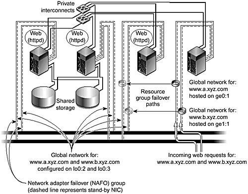
Hosting the global IP address on the loopback interface prevents the node from accepting incoming packets directly from the network while forcing the TCP/IP to adopt the address as local. Once the global IP packet is routed through the private interconnect to the TCP/IP stack of the node, the system acknowledges the destination address as internal and processed. The system sends a response packet (with the global IP as the source address) to the network because there is a network interface with an IP address on the same subnet on the node hosts. These services can then be brought up on these nodes and bound to the global IP address.
Scalable services, such as the iPlanet Web Server, are described in more detail throughout the following sections.
Packet Distribution Mechanisms
When the GIF accepts an incoming IP packet destined for a scalable service, the packet dispatch table (PDT) driver first examines the packet before passing it any further up the IP stack. Currently, the PDT has three policies for packet distribution—weighted, the system default; ordinary sticky, and wildcard sticky.
The weighted policy hashes incoming packets into buckets that are associated with the nodes hosting the target application, in accordance with their source IP and port number. By default, each node is given one entry in the hash array. So for three nodes, there would be three entries; each node would, statistically, get one-third of the overall traffic. The system then transfers the packets to the target node over the private interconnect to present them for consumption by the application on the loopback interface. When the application responds, the system transmits the outgoing packets using the relevant local NIC. You can change load-balancing weights dynamically at any time with the scrgadm(1M) command without shutting down dependent applications. For example, in a three-node system, the nodes A, B, and C could be given weights of 10, 30, and 40 (note that the weights do not need to add up to 100). In this case, the nodes get one-eighth, three-eighths, and one-half of the total traffic, respectively.
Under a weighted policy, packets from an individual client node that are sent from a fixed port are always hashed to the same destination server. Only a change in the weighting policy or the failure of one of the target nodes would alter the distribution by changing the result of the hash calculation. In the preceding example, if node B fails, node A would get one-fifth of the packets, and node C four-fifths of the packets.
The ordinary sticky policy ensures that requests from a given client IP address to a particular destination port are always directed to the same node hosting the target scalable service. This enables concurrent client connections to target nodes to share in-memory state. A good example of where this functionality is useful is an e-commerce site. The shopper can browse through the goods available and fill the shopping cart through one connection and service (HTTP on port 80) and then use a second connection and service (SSL on port 443) to pay for the goods. Having a fixed target node for packets avoids the overhead of renegotiating the SSL credentials every time a packet goes to a different host. Renegotiating the credentials every time a packet goes to a different host is a computation-expensive operation that is best minimized.
Application services that dynamically allocate ports, such as a passive mode FTP service, the initial connection on port 21 must be redirected to another port chosen by the service. This type of service must use the wildcard sticky policy. Under the wildcard sticky policy, all packets from a client IP address are directed to the same target node, regardless of their destination port.
Client affinity, the mapping of client traffic to a target server and service, remains in place unless the weighting distribution is changed or a target node or service becomes unavailable. If the weighting changes, existing connections can be distributed to a new target node. After a node or service failure and subsequent recovery, TCP-based applications reinstate their previous target affinity. However, this is not guaranteed to be the case with UDP-based applications.
Sun Cluster 3.0 allows both many-to-many and one-to-many relationships between services and global IP addresses. A three-node cluster, with nodes A, B, and C, can host the global IP www.xyz.com on the public network interface of node A. The system can also be configured with a scalable web service on port 80 on nodes A, B, and C and another scalable web service on port 90 on nodes A and B only. In contrast, the same cluster could host two global IP addresses: www.xyz.com and www.abc.com on node A and B respectively, both with scalable web services on port 80 running on all three nodes. Further, either of these configurations could be combined with additional failover services as required or as resources allow.
Advantages
The global networking service enables the cluster to provide scalable outbound IP traffic. This increases both throughput and response time without requiring any additional load-balancing hardware or software. Typically, inbound client network traffic is much smaller than the outbound network traffic it generates. Because of its tight integration with the cluster framework, this mechanism also ensures that the PDT driver does not distribute packets to nodes that are not currently participating in a cluster.
At first it might seem that the GIF is a system bottleneck. However, most workloads that are amenable to becoming scalable services have traffic profiles in which outbound packets outnumber inbound ones by as much as six to one. Most web servers and streaming media services are in this category.
Client Connection Recovery After a GIN Node Failure
A global IP address is defined as an instance of a SUNW.SharedAddress resource and placed in a failover resource group. See “Data Services and Application Agents”. If the node that is hosting one or more GIFs fails, the system reconfigures the address(es) onto an appropriate public network interface of another cluster node, defined in the resource group as a potential host for the GIF. IP packets reestablish their flow through the new GIN and are forwarded to the subscribing services as before. The public network monitoring (PNM) facility (see “Public Network Monitoring”) protects the GIF against NIC or network failure on the GIN.
From a client IP perspective, the global network service is available continuously. As part of the standard TCP/IP recovery mechanisms, the system retransmits packets dropped while the interface is being moved. If the application is UDP based, it retransmits lost packets. To applications on both the client and the cluster, the global IP address functions identically to IP addresses on a single server; no application changes are required. You can migrate the global IP addresses with the scswitch(1M) command.
Private Interconnects
Nodes in a Sun Cluster 3.0 system need networks over and above those required to provide client connectivity. Therefore, Sun Cluster 3.0 uses private interconnects to transmit and receive cluster heartbeat messages and a variety of other information between nodes. As with all other components in a cluster, the system requires a minimum of two private interconnects for redundancy. Although there is no inherent limitation on the number of interconnects that the system can support, Sun Cluster 3.0 imposes a practical limit of six private interconnects on cluster configurations. Bear in mind that these connections consume CPU cycles to send and receive packets. Six Gigabit Ethernet connections using the current Gigabit Ethernet cards could take as many as six 750 MHz UltraSPARC III CPUs to drive to full capacity.
Private interconnects cannot share switches or use routers because the routers would not route the DLPI heartbeat traffic. See “DLPI”.
For clusters with only two nodes, simple back-to-back (direct connection) cabling suffices. Larger clusters need multiple switches, one for each private connection. Multiple connections are particularly beneficial when the global features described previously are heavily used. FIGURE 3-14 shows back-to-back and switch-connected private interconnects.
Figure 3-14. Switch-Connected and Back-to-Back Private Interconnects

Sun Cluster 3.0 allows you to dynamically add and remove private interconnects without taking down the cluster or stopping the applications. In addition, it supports arbitrary interconnect topologies, allowing some node pairs to have more shared interconnect bandwidth than others. For example, a three-node pair+M topology, with nodes A, B, and C, could have an additional private interconnect between B and C only, over and above the minimum dual connectivity between all the hosts. Currently, Sun Cluster 3.0 supports 100BASE-T and Gigabit Ethernet as private interconnect networks.
Traffic
The cluster uses the private interconnects to transmit a variety of information. The most important communications of all are the regular cluster heartbeat messages. Each node sends a message to its cluster peers every dlpi_heartbeat_quantum milliseconds, as defined in the CCR. The message contains a timestamp and an echo of the last timestamp value it received from that peer. If the last echoed timestamp is older than dlpi_heartbeat_timeout milliseconds when a node receives a message, the path is declared down. For example, if node A receives regular heartbeats from node B but they have old timestamps (because node B has not received a message from node A recently), node A declares the path down despite receiving heartbeats. If all paths between a pair of nodes are lost, the cluster membership monitor (see “Cluster Membership”) maintains cluster integrity.
Note
Neither the dlpi_heartbeat_quantum interval nor the dlpi_heartbeat_timeout can be tuned.
To handle situations in which the nodes are receiving DLPI heartbeats but no TCP/IP messages are getting through, the private interconnect also employs a TCP/IP timeout. If the cluster cannot send a message queued for a particular path within 90 seconds, it declares that path down. The cluster then brings down the path and attempts to re-establish the path. Meanwhile, the system independently sends the message again, through an alternate path.
Applications that access global devices, such as RDBMSs implemented on raw global partitions, need these interconnect services. To ensure that primary and secondary I/O paths remain synchronized, the replica framework sends messages. If the application and the primary I/O path are not colocated, the interconnect services transfer bulk data too. Similarly, an application that relies on the CFS generates corresponding amounts of interconnect traffic.
Scalable applications, such as the iPlanet and Apache web servers, also require the private interconnect to mediate global IP traffic distribution because the system forwards packets over the interconnects once the PDT establishes the target node.
The cluster framework assigns each node a highly available, private IP address, which the system installer defines during the initial cluster setup. The loopback interface of the particular node hosts this address. Cluster-aware applications, such as Oracle 9i RAC, can use this IP connection to provide a reliable transport mechanism for distributed lock managers and other internode communication protocols.
Resiliency
A cluster can survive multiple failures of the private interconnect infrastructure. The cluster continues to function without loss of service and without requiring any node shutdowns as long as each node has a path to connect it to every other current cluster member. The cluster transport drivers load-balance the cluster framework messages, on a simple round-robin basis, across the available interconnect. Thus, multiple requests benefit transparently from the parallelism that the multiple connections offer.
Protocols
Cluster internode communication protocols depend on the transport configured. For connections based on 100BASE-T or Gigabit Ethernet, the private interconnect uses DLPI and TCP/IP messages. Future interconnects will support DLPI and be able to take advantage of the RSM protocol. Both RSM and DLPI are implemented with optimizations to enable bulk data transfer and efficient buffer allocation with respect to the underlying hardware.
TCP/IP
Despite being inexpensive, an Ethernet connection has the overhead of encapsulating each message in one or more TCP/IP packets. These packets then pass through the respective TCP/IP stacks on both the sending and receiving cluster nodes. For servers connected back-to-back over a distance of less than 10 meters, this process normally causes a packet latency of about 300 microseconds. Although this latency sounds insignificant, you must compare it with local memory accesses within a server. Typically, these accesses take about 200 nanoseconds. Thus, on average, messages that must be sent between servers take 1,500 times longer to arrive than if they are written directly into local memory.
Whenever the cluster framework makes an ORB call that accesses or passes data to a remote object, it uses a TCP/IP message. Each of these messages incurs the TCP/IP packet overhead.
The network interfaces that constitute the private interconnect are allocated addresses from the IP network number provided during installation. By default, the 172.16.0.0 network address is used. Additionally, the loopback interface, lo0:1, has an address from this network. Preferably, if you choose an alternative address during installation, you should select an unrouted address.
DLPI
Heartbeat messages use a low-level DLPI mechanism to determine cluster connectivity. The data is sent as raw Ethernet packets that contain the node IDs of the sender and receiver, cluster incarnation number, and two timestamps. The system generates the timestamps in the message from the current time on the sending node plus the timestamp previously received from the peer node. Because the DLPI interface uses medium access control (MAC) addresses, the heartbeat cannot be routed.
RSM
The Remote Shared Memory (RSM) protocol enables the system to transfer messages directly into a range of memory addresses that correspond to the receiving buffer on the remote server. This method avoids the overhead of putting the message in a TCP/IP packet as described previously, thus reducing the raw latency associated with sending a message between nodes to around 10 microseconds or less. However, an overhead is still associated with the Sun Cluster 3.0 protocol stacks. The potential performance improvements associated with an RSM-capable transport have not yet been characterized.
Applications written to use the RSM-API will be the first to benefit from the RSM protocol. This protocol enables applications to perform bulk data transfer, through the interconnect, without the TCP/IP overhead. The Peripheral Component Interconnect-Scalable Coherent Interface (PCI-SCI) card is the first RSM-capable card. When the PCI-SCI card becomes available, it will also support the standard DLPI protocol described previously.
Future developments will provide a mechanism to enable cluster framework messages to be sent using the RSM protocol. The potential performance improvements have yet to be characterized.
Configuration Guidelines
Despite the drawback listed previously, many workloads perform well with Ethernet-based private interconnects. A reasonable rule of thumb is to consider 100BASE-T for low-end clusters when cost is an issue or I/O expansion slots are at a premium. For midrange and some high-end clusters, Gigabit Ethernet connections are advisable. The number of connections the system requires depends on the I/O characteristics of the disk and the network workloads being supported. For larger cluster configurations running Oracle 9i RAC and using the RSM-API, you should consider PCI-SCI where and when this option is supported.
It is unlikely that the private interconnect throughput will cause I/O bottlenecks within a cluster. Tests show that interconnect throughput scales linearly as more networks are added. As a rough guide, an extra 100BASE-T adds about 7 megabytes/sec of internode throughput, whereas a Gigabit Ethernet adds around 70 megabytes/sec. Most commercial OLTP workloads are unlikely to exceed 70 megabytes/sec.
Cluster Configuration Control
To maintain an accurate and up-to-date representation of configuration information, clustered systems require configuration control. Sun Cluster 3.0 uses a cluster configuration repository (CCR) to store the most recent configuration information.
Configuration Repository
Sun Cluster 3.0 stores its configuration details in the cluster configuration repository (CCR). This repository is a set of ASCII files that resides on the root file system in the /etc/cluster/ccr directory. The storage requirement for the CCR is relatively modest. Even the largest foreseeable configuration uses less than one megabyte.
These files contain the following information:
Cluster name
Cluster nodes
Node IP addresses
Private interconnect topology
Details of quorum devices
Details of resource groups, resource types, and resources
Device ID (DID) instances
Details of device groups
By storing the CCR in multiple files, the cluster increases the failure resilience of the system. A corruption or error in one file does not preclude the consistent update of the remaining files.
The system requires some of the information in the CCR tables at boot time—for example, the node key for PGR/PGRe registration, the cluster name and transport information, and so forth.
A read-only mode enables the system to read the required information before the consistency of the tables is established. When the node successfully joins the cluster, the system puts the tables in read/write mode.
File Consistency
The cluster framework maintains the consistency of the CCR files by using a distributed two-phase commit protocol, implemented as a highly available kernel component. See “Replica Management”. This implementation reduces the susceptibility of the update procedure to resource starvation that can occur if it is implemented as a user-level process or daemon.
CCR changes can be made with the appropriate cluster commands—scrgadm(1M), scsetup(1M), and scconf(1M). Each file has its own timestamp and checksum to guarantee its integrity.
Caution
The CCR files should not be edited manually. Inconsistent manual changes can lead to a cluster-wide failure and failure of the member nodes to boot. The recovery procedure will then require one or more nodes to be booted in noncluster mode with the OBP boot command -x flag.
Amnesia and Temporally Split Configurations
A clustered system relies on the CCR for an accurate, up-to-date, representation of its configuration information. To maintain cluster integrity and assure application data integrity, the cluster nodes must not have conflicting CCR information.
Each cluster node and dual-hosted quorum disk defined within the cluster contribute one vote to the majority vote. As long as the cluster retains a majority of these votes, it continues to run. When this is true, changes can be made to the CCR. For an overview of the voting mechanism, see “Voting and Quorum” and “Majority Voting and Quorum Principles”.
The cluster membership model governed by this majority voting mechanism ensures that only nodes that were members of the last valid cluster configuration have an up-to-date version of the CCR. The presence of emulated SCSI-3 PGR keys on the quorum disks prevents nodes that were not members of this final incarnation from completing their booting process. This action prevents the formation of a new cluster by a node with stale (out-of-date) CCR information. An amnesiac cluster cannot start the correct service, and can even corrupt user data.