Kernel Infrastructure
Most traditional clusters, such as Sun Cluster 2.2 and other competing clustering products, relied on layering collections of compiled programs and shell scripts on top of a plain operating system. Sun Cluster 3.0 offers enhanced functionality because it is tightly integrated with the Solaris 8 operating environment and the system interconnects. The following sections highlight the problems the Sun hardware engineers and software developers had to overcome and extols the benefits of their solutions. These sections contain an overview of how participating cluster nodes interact, an overview of the supporting kernel framework, and a description of replica management. FIGURE 3-2 shows a basic Sun Cluster 3.0 system hardware configuration.
Figure 3-2. Sun Cluster 3.0 System Hardware Diagram

Subject to certain configuration guidelines, participating nodes can be individual physical servers or system domains within Sun Enterprise™ 10000 and Sun Fire systems. Multiple private interconnect networks connect every node with the other nodes and one or more of the public network subnets to provide resilient user connectivity. Each server in the cluster runs a separate copy of the Solaris 8 operating environment.
Depending on the storage topology used, one or more pairs of nodes can support dual-hosted disk subsystems. You can use standard disk management products, such as Solaris Volume Manager (SVM), formerly known as Solstice DiskSuite™, or VERITAS Volume Manager (VxVM) to manage the disk space. Currently, Sun Cluster 3.0 supports only the Solaris UNIX File System (UFS). Support for the VERITAS File System (VxFS) is expected at a later date.
Installing the Sun Cluster 3.0 software makes available the global features—global file service, global devices, and global networking. These features enable the cluster to provide highly available, scalable, and parallel services.
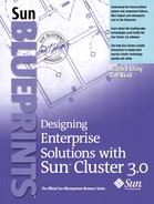
Kernel Framework
The Sun Cluster 3.0 software extends the Solaris 8 operating environment into a cluster operating system through a number of kernel components that work together to overcome the technical problems of cluster computing described in Chapter 1. FIGURE 3-3 shows the relationship between these components and their user interfaces.
Figure 3-3. Relationship Between Sun Cluster Components
The ps(1) command lists the processes:
cluster— This process is the user-level representation of the cluster kernel processes, similar in concept to the sched or pageout processes. These processes control all the cluster kernel threads and the object request broker (ORB).
clexecd— This process performs some user-level file system tasks on behalf of the cluster framework, for example, file system checking of the VxFS file systems when Sun Cluster 3.0 supports VxFS.
Subsequent paragraphs in this chapter cover other cluster-related processes.
The design basis of the cluster kernel framework is the ORB model. The distributed object invocation service is similar to the Common Object Request Broker Architecture (CORBA) model. Interfaces used by the cluster kernel components are described with the CORBA Interface Definition Language (IDL); components interact with one another by making requests on the interfaces of a component. The same node or another node then executes these requests regardless of the location of the object. When object invocation is on the local node, the system executes the call as a virtual function call and accesses objects hosted on a remote node by remote object invocation over the private interconnects of the cluster.
Replica Management
One of the main problems that Sun Cluster 3.0 overcomes is the maintenance of the distributed state of a number of its fundamental kernel components. The system achieves this by using a combination of replica managers (RM), replica manager agents (RMA), and a single replica manager (RMM).
Components within the cluster kernels interact with each other on a client/server basis. The global file service (GFS) is two separate pieces, each of which can reside on a separate node. For a client caller to receive a highly available service from a server object, an alternative server, or secondary server, located on another node must back up that object. The system also uses the concept of a standby object that can be promoted to the status of a secondary object if a secondary server must take over from a primary server. This mechanism ensures the continued availability of the object, even if a subsequent failure occurs, without the overhead of continuously updating multiple secondaries. However, this immediately leads to all of the associated clustered computing synchronization and arbitration problems described in Chapter 1. The standard Solaris operating environment has no kernel transactional facilities to support this requirement, so Sun Cluster 3.0 provides these facilities.
Mini-Transactions
A series of mini-transactions that implement a two-phase commit protocol synchronize the primary servers with one or more secondary servers. This protocol is similar to that found in modern distributed database systems. Using this protocol ensures that synchronous writes to two different memories are consistent, as described in “Microprocessor Cache Coherency” and “Two-Phase Commit”.
FIGURE 3-4 shows the sequence of operations on a typical replicated object. The mini-transaction framework ensures “exactly once” semantics. Exactly once semantics ensure that an operation is not duplicated or repeated. In comparison, atomic operations ensure only that an operation either succeeds or does not succeed. Not only do exactly once semantics make kernel services highly available, but they mask a range of failures from user applications. The replica object handler of a service communicates with its replicas to atomically execute the request of the client object. The primary replica is then responsible for sending checkpoint messages to the secondary replica. These messages are service dependent but the effect is identical. The secondary replies with a commit message, and the primary logs the operation before replying to the client object. When the client completes the call successfully, it replies asynchronously to the primary replica to notify this replica to forget the operation.
Figure 3-4. Mini-Transaction Replicated Object Sequence

An example of file creation on a cluster file system demonstrates how replicas work in practice and clarifies their work and benefit to user applications. A cluster file system is mounted concurrently on all of the current member nodes within a cluster. The underlying disk subsystem hosting the file system is connected to both cluster nodes simultaneously, but the I/O to the file system passes through only one controlling node (see “Storage Topologies”), the primary path, at any one time. For the file system to appear continuously available to client applications, all I/O operations that modify the state of the file system need the services of the replica manager.
Consider the operation of file creation on a file system. This operation must first check for the existence of the file, its permissions, and the permissions of the directory containing the file. If the file does not exist and the permissions settings allow, the system can then create the file, along with appropriate updates associated with file creation before the call returns to the user. The operation also returns the appropriate UNIX success or error return code.