Fault Tree Analysis
Fault tree analysis (FTA) is a deductive, top-down method of analyzing system design. It is considered one of the best methods for systematically identifying and graphically displaying the many ways something can go wrong. First, you specify an undesirable top event. Then you identify all of the components in the system that could cause that top event. The components can contribute failure probabilities. You can use Boolean logic to describe the relationship between the components. This method enables you to describe a complex system in much the same way as a digital electronic logic circuit.
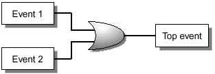
Generally, you do FTA graphically by using a Boolean logic structure of AND and OR gates (FIGURE D-1 and FIGURE D-2). To describe very complex systems, you can used additional logic gates. You can also decompose systems into subsystems that use the same logical relationships. This method enables you to analyze very complex systems in a hierarchal manner.
Figure D-1. AND Gate Structure Analysis

![]()
![]()
Figure D-2. OR Gate Structure Analysis

![]()
![]()
For convenience, one additional logical grouping, in which the function includes a sum and a conditional, is occasionally used. This grouping is useful when M out of N basic events must occur. An example would be an N+1 power supply subsystem. If N = 2, there are three total power supplies, but only two must be operational. This logical gate could be constructed out of AND and OR gates, but for more than two inputs, the number of logic gates required to implement the logic becomes tedious, confusing, and error prone. Unfortunately, there is no Boolean logic gate that describes such a function, so a functional block provides clarity (FIGURE D-3).
Figure D-3. Functional Block Structure Analysis

![]()
The probabilistic view is more complicated. For FTA, we are concerned with minimal cut sets, cut sets that are not a subset of any other cut set. In the logical view (FIGURE D-3), (Event1 • Event2 • Event3) is not a minimal cut set. To simplify the expression, the minimal cut sets are:
![]()
![]()
![]()
![]()
Obviously, a tool for calculating these probabilities helps to reduce the analysis time.
Building for Analysis
To build a fault tree for analysis:
Identify the top event.
This event can be as simple as a service outage.
Identify components that can affect the top event.
This identification begins the iterative process of examining every component in the architecture that may have a relationship to the top event.
Describe the relationships between the components and the top event.
This description builds the relationships between components into a model that can be analyzed.
FIGURE D-4 is an example of a fault tree for the boot, root, and swap disk subsystem described in “Boot Environment”.
In this example, the bottom layers represent actual hardware and interconnections. The RAID software manages the presentation of the LUNs to the operating environment. The relationship between the components is clearly shown with dual redundant components feeding into the AND gates. The inputs to the model would be the probability distribution functions for failure of the components. The resulting probability function of the service failure is a complex function, best solved by a modelling program. For simple models, a spreadsheet can be used, but the logical representation is difficult to visualize in a spreadsheet.
Inspecting an FTA
One simple approach to looking at FTA is:
AND gates represent redundancy and tend to improve system availability.
OR gates represent dependency and tend to decrease system availability.
However, sometimes the AND gate introduces an OR gate that must be considered. The implied OR gate represents the arbitration and synchronization that is required by active or data components in an architecture.
The example in FIGURE D-4 shows the effects on the system architecture when redundant components are added.
Figure D-4. Fault Tree Analysis of Boot, Root, and Swap Disk Subsystem

In FIGURE D-4 the power supplies, PS0 and PS1, are designed to load share. However, no active logic can decide which power supply delivers power to the power subsystem. When both power supplies are functional, each supply shares the load.
When only one power supply is functional, it has enough capacity to supply the required power to the subsystem. In this case, a simple AND gate represents the redundancy. However, this type of load sharing is not properly modelled by FTA, and the mathematics are fairly complicated. Rather, the FTA model for the power supplies is defined as actively redundant. From a practical perspective, the options available to the systems engineer are few, and load-sharing power supplies are a better option for availability than single power supplies. Therefore, it may be more practical to model the power supplies as actively redundant than to create an overly complicated model.
The top-level event requires the use of disk mirroring software to present a single, logical view to the application. This is the role of the logical volume manager (LVM). Failures in the LVM will affect the service. Building a redundant LVM does not work, because some higher level mechanism must provide the arbitration and synchronization between the LVMs. Thus, you must design and build the LVM to be as resilient as possible.
