5 Thread-Level Parallelism
The turning away from the conventional organization came in the middle 1960s, when the law of diminishing returns began to take effect in the effort to increase the operational speed of a computer…. Electronic circuits are ultimately limited in their speed of operation by the speed of light … and many of the circuits were already operating in the nanosecond range.
W. Jack Bouknight et al., The Illiac IV System (1972)
We are dedicating all of our future product development to multicore designs. We believe this is a key inflection point for the industry.
Intel President Paul Otellini, describing Intel’s future direction at the Intel Developer Forum in 2005
5.1 Introduction
As the quotations that open this chapter show, the view that advances in uni-processor architecture were nearing an end has been held by some researchers for many years. Clearly, these views were premature; in fact, during the period of 1986–2003, uniprocessor performance growth, driven by the microprocessor, was at its highest rate since the first transistorized computers in the late 1950s and early 1960s.
Nonetheless, the importance of multiprocessors was growing throughout the 1990s as designers sought a way to build servers and supercomputers that achieved higher performance than a single microprocessor, while exploiting the tremendous cost-performance advantages of commodity microprocessors. As we discussed in Chapters 1 and 3, the slowdown in uniprocessor performance arising from diminishing returns in exploiting instruction-level parallelism (ILP) combined with growing concern over power, is leading to a new era in computer architecture—an era where multiprocessors play a major role from the low end to the high end. The second quotation captures this clear inflection point.
This increased importance of multiprocessing reflects several major factors:
In this chapter, we focus on exploiting thread-level parallelism (TLP). TLP implies the existence of multiple program counters and hence is exploited primarily through MIMDs. Although MIMDs have been around for decades, the movement of thread-level parallelism to the forefront across the range of computing from embedded applications to high-end severs is relatively recent. Likewise, the extensive use of thread-level parallelism for general-purpose applications, versus scientific applications, is relatively new.
Our focus in this chapter is on multiprocessors, which we define as computers consisting of tightly coupled processors whose coordination and usage are typically controlled by a single operating system and that share memory through a shared address space. Such systems exploit thread-level parallelism through two different software models. The first is the execution of a tightly coupled set of threads collaborating on a single task, which is typically called parallel processing. The second is the execution of multiple, relatively independent processes that may originate from one or more users, which is a form of request-level parallelism, although at a much smaller scale than what we explore in the next chapter. Request-level parallelism may be exploited by a single application running on multiple processors, such as a database responding to queries, or multiple applications running independently, often called multiprogramming.
The multiprocessors we examine in this chapter typically range in size from a dual processor to dozens of processors and communicate and coordinate through the sharing of memory. Although sharing through memory implies a shared address space, it does not necessarily mean there is a single physical memory. Such multiprocessors include both single-chip systems with multiple cores, known as multicore, and computers consisting of multiple chips, each of which may be a multicore design.
In addition to true multiprocessors, we will return to the topic of multithreading, a technique that supports multiple threads executing in an interleaved fashion on a single multiple issue processor. Many multicore processors also include support for multithreading.
In the next chapter, we consider ultrascale computers built from very large numbers of processors, connected with networking technology and often called clusters; these large-scale systems are typically used for cloud computing with a model that assumes either massive numbers of independent requests or highly parallel, intensive compute tasks. When these clusters grow to tens of thousands of servers and beyond, we call them warehouse-scale computers.
In addition to the multiprocessors we study here and the warehouse-scaled systems of the next chapter, there are a range of special large-scale multiprocessor systems, sometimes called multicomputers, which are less tightly coupled than the multiprocessors examined in this chapter but more tightly coupled than the warehouse-scale systems of the next. The primary use for such multicomputers is in high-end scientific computation. Many other books, such as Culler, Singh, and Gupta [1999], cover such systems in detail. Because of the large and changing nature of the field of multiprocessing (the just-mentioned Culler et al. reference is over 1000 pages and discusses only multiprocessing!), we have chosen to focus our attention on what we believe is the most important and general-purpose portions of the computing space. Appendix I discusses some of the issues that arise in building such computers in the context of large-scale scientific applications.
Thus, our focus will be on multiprocessors with a small to moderate number of processors (2 to 32). Such designs vastly dominate in terms of both units and dollars. We will pay only slight attention to the larger-scale multi-processor design space (33 or more processors), primarily in Appendix I, which covers more aspects of the design of such processors, as well as the behavior performance for parallel scientific workloads, a primary class of applications for large-scale multiprocessors. In large-scale multiprocessors, the interconnection networks are a critical part of the design; Appendix F focuses on that topic.
Multiprocessor Architecture: Issues and Approach
To take advantage of an MIMD multiprocessor with n processors, we must usually have at least n threads or processes to execute. The independent threads within a single process are typically identified by the programmer or created by the operating system (from multiple independent requests). At the other extreme, a thread may consist of a few tens of iterations of a loop, generated by a parallel compiler exploiting data parallelism in the loop. Although the amount of computation assigned to a thread, called the grain size, is important in considering how to exploit thread-level parallelism efficiently, the important qualitative distinction from instruction-level parallelism is that thread-level parallelism is identified at a high level by the software system or programmer and that the threads consist of hundreds to millions of instructions that may be executed in parallel.
Threads can also be used to exploit data-level parallelism, although the overhead is likely to be higher than would be seen with an SIMD processor or with a GPU (see Chapter 4). This overhead means that grain size must be sufficiently large to exploit the parallelism efficiently. For example, although a vector processor or GPU may be able to efficiently parallelize operations on short vectors, the resulting grain size when the parallelism is split among many threads may be so small that the overhead makes the exploitation of the parallelism prohibitively expensive in an MIMD.
Existing shared-memory multiprocessors fall into two classes, depending on the number of processors involved, which in turn dictates a memory organization and interconnect strategy. We refer to the multiprocessors by their memory organization because what constitutes a small or large number of processors is likely to change over time.
The first group, which we call symmetric (shared-memory) multiprocessors (SMPs), or centralized shared-memory multiprocessors, features small numbers of cores, typically eight or fewer. For multiprocessors with such small processor counts, it is possible for the processors to share a single centralized memory that all processors have equal access to, hence the term symmetric. In multicore chips, the memory is effectively shared in a centralized fashion among the cores, and all existing multicores are SMPs. When more than one multicore is connected, there are separate memories for each multicore, so the memory is distributed rather than centralized.
SMP architectures are also sometimes called uniform memory access (UMA) multiprocessors, arising from the fact that all processors have a uniform latency from memory, even if the memory is organized into multiple banks. Figure 5.1 shows what these multiprocessors look like. The architecture of SMPs is the topic of Section 5.2, and we explain the approach in the context of a multicore.
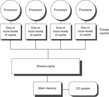
Figure 5.1 Basic structure of a centralized shared-memory multiprocessor based on a multicore chip. Multiple processor–cache subsystems share the same physical memory, typically with one level of shared cache, and one or more levels of private per-core cache. The key architectural property is the uniform access time to all of the memory from all of the processors. In a multichip version the shared cache would be omitted and the bus or interconnection network connecting the processors to memory would run between chips as opposed to within a single chip
The alternative design approach consists of multiprocessors with physically distributed memory, called distributed shared memory (DSM). Figure 5.2 shows what these multiprocessors look like. To support larger processor counts, memory must be distributed among the processors rather than centralized; otherwise, the memory system would not be able to support the bandwidth demands of a larger number of processors without incurring excessively long access latency. With the rapid increase in processor performance and the associated increase in a processor’s memory bandwidth requirements, the size of a multiprocessor for which distributed memory is preferred continues to shrink. The introduction of multicore processors has meant that even two-chip multiprocessors use distributed memory. The larger number of processors also raises the need for a high-bandwidth inter-connect, of which we will see examples in Appendix F. Both directed networks (i.e., switches) and indirect networks (typically multidimensional meshes) are used.

Figure 5.2 The basic architecture of a distributed-memory multiprocessor in 2011 typically consists of a multicore multiprocessor chip with memory and possibly I/O attached and an interface to an interconnection network that connects all the nodes. Each processor core shares the entire memory, although the access time to the lock memory attached to the core’s chip will be much faster than the access time to remote memories.
Distributing the memory among the nodes both increases the bandwidth and reduces the latency to local memory. A DSM multiprocessor is also called a NUMA (nonuniform memory access), since the access time depends on the location of a data word in memory. The key disadvantages for a DSM are that communicating data among processors becomes somewhat more complex, and a DSM requires more effort in the software to take advantage of the increased memory bandwidth afforded by distributed memories. Because all multicore-based multiprocessors with more than one processor chip (or socket) use distributed memory, we will explain the operation of distributed memory multiprocessors from this viewpoint.
In both SMP and DSM architectures, communication among threads occurs through a shared address space, meaning that a memory reference can be made by any processor to any memory location, assuming it has the correct access rights. The term shared memory associated with both SMP and DSM refers to the fact that the address space is shared.
In contrast, the clusters and warehouse-scale computers of the next chapter look like individual computers connected by a network, and the memory of one processor cannot be accessed by another processor without the assistance of software protocols running on both processors. In such designs, message-passing protocols are used to communicate data among processors.
Challenges of Parallel Processing
The application of multiprocessors ranges from running independent tasks with essentially no communication to running parallel programs where threads must communicate to complete the task. Two important hurdles, both explainable with Amdahl’s law, make parallel processing challenging. The degree to which these hurdles are difficult or easy is determined both by the application and by the architecture.
The first hurdle has to do with the limited parallelism available in programs, and the second arises from the relatively high cost of communications. Limitations in available parallelism make it difficult to achieve good speedups in any parallel processor, as our first example shows.
Example
Suppose you want to achieve a speedup of 80 with 100 processors. What fraction of the original computation can be sequential?
Answer
Recall from Chapter 1 that Amdahl’s law is

For simplicity in this example, assume that the program operates in only two modes: parallel with all processors fully used, which is the enhanced mode, or serial with only one processor in use. With this simplification, the speedup in enhanced mode is simply the number of processors, while the fraction of enhanced mode is the time spent in parallel mode. Substituting into the previous equation:

Simplifying this equation yields:

Thus, to achieve a speedup of 80 with 100 processors, only 0.25% of the original computation can be sequential. Of course, to achieve linear speedup (speedup of n with n processors), the entire program must usually be parallel with no serial portions. In practice, programs do not just operate in fully parallel or sequential mode, but often use less than the full complement of the processors when running in parallel mode.
The second major challenge in parallel processing involves the large latency of remote access in a parallel processor. In existing shared-memory multiprocessors, communication of data between separate cores may cost 35 to 50 clock cycles and among cores on separate chips anywhere from 100 clock cycles to as much as 500 or more clock cycles (for large-scale multiprocessors), depending on the communication mechanism, the type of interconnection network, and the scale of the multiprocessor. The effect of long communication delays is clearly substantial. Let’s consider a simple example.
Example
Suppose we have an application running on a 32-processor multiprocessor, which has a 200 ns time to handle reference to a remote memory. For this application, assume that all the references except those involving communication hit in the local memory hierarchy, which is slightly optimistic. Processors are stalled on a remote request, and the processor clock rate is 3.3 GHz. If the base CPI (assuming that all references hit in the cache) is 0.5, how much faster is the multiprocessor if there is no communication versus if 0.2% of the instructions involve a remote communication reference?
Answer
It is simpler to first calculate the clock cycles per instruction. The effective CPI for the multiprocessor with 0.2% remote references is
The remote request cost is
Hence, we can compute the CPI:
The multiprocessor with all local references is 1.7/0.5 = 3.4 times faster. In practice, the performance analysis is much more complex, since some fraction of the noncommunication references will miss in the local hierarchy and the remote access time does not have a single constant value. For example, the cost of a remote reference could be quite a bit worse, since contention caused by many references trying to use the global interconnect can lead to increased delays.
These problems—insufficient parallelism and long-latency remote communication—are the two biggest performance challenges in using multiprocessors. The problem of inadequate application parallelism must be attacked primarily in software with new algorithms that offer better parallel performance, as well as by software systems that maximize the amount of time spent executing with the full complement of processors. Reducing the impact of long remote latency can be attacked both by the architecture and by the programmer. For example, we can reduce the frequency of remote accesses with either hardware mechanisms, such as caching shared data, or software mechanisms, such as restructuring the data to make more accesses local. We can try to tolerate the latency by using multithreading (discussed later in this chapter) or by using prefetching (a topic we cover extensively in Chapter 2).
Much of this chapter focuses on techniques for reducing the impact of long remote communication latency. For example, Sections 5.2 through 5.4 discuss how caching can be used to reduce remote access frequency, while maintaining a coherent view of memory. Section 5.5 discusses synchronization, which, because it inherently involves interprocessor communication and also can limit parallelism, is a major potential bottleneck. Section 5.6 covers latency-hiding techniques and memory consistency models for shared memory. In Appendix I, we focus primarily on larger-scale multiprocessors that are used predominantly for scientific work. In that appendix, we examine the nature of such applications and the challenges of achieving speedup with dozens to hundreds of processors.
5.2 Centralized Shared-Memory Architectures
The observation that the use of large, multilevel caches can substantially reduce the memory bandwidth demands of a processor is the key insight that motivates centralized memory multiprocessors. Originally, these processors were all single-core and often took an entire board, and memory was located on a shared bus. With more recent, higher-performance processors, the memory demands have outstripped the capability of reasonable buses, and recent microprocessors directly connect memory to a single chip, which is sometimes called a backside or memory bus to distinguish it from the bus used to connect to I/O. Accessing a chip’s local memory whether for an I/O operation or for an access from another chip requires going through the chip that “owns” that memory. Thus, access to memory is asymmetric: faster to the local memory and slower to the remote memory. In a multicore that memory is shared among all the cores on a single chip, but the asymmetric access to the memory of one multicore from the memory of another remains.
Symmetric shared-memory machines usually support the caching of both shared and private data. Private data are used by a single processor, while shared data are used by multiple processors, essentially providing communication among the processors through reads and writes of the shared data. When a private item is cached, its location is migrated to the cache, reducing the average access time as well as the memory bandwidth required. Since no other processor uses the data, the program behavior is identical to that in a uniprocessor. When shared data are cached, the shared value may be replicated in multiple caches. In addition to the reduction in access latency and required memory bandwidth, this replication also provides a reduction in contention that may exist for shared data items that are being read by multiple processors simultaneously. Caching of shared data, however, introduces a new problem: cache coherence.
What Is Multiprocessor Cache Coherence?
Unfortunately, caching shared data introduces a new problem because the view of memory held by two different processors is through their individual caches, which, without any additional precautions, could end up seeing two different values. Figure 5.3 illustrates the problem and shows how two different processors can have two different values for the same location. This difficulty is generally referred to as the cache coherence problem. Notice that the coherence problem exists because we have both a global state, defined primarily by the main memory, and a local state, defined by the individual caches, which are private to each processor core. Thus, in a multicore where some level of caching may be shared (for example, an L3), while some levels are private (for example, L1 and L2), the coherence problem still exists and must be solved.

Figure 5.3 The cache coherence problem for a single memory location (X), read and written by two processors (A and B). We initially assume that neither cache contains the variable and that X has the value 1. We also assume a write-through cache; a write-back cache adds some additional but similar complications. After the value of X has been written by A, A’s cache and the memory both contain the new value, but B’s cache does not, and if B reads the value of X it will receive 1!
Informally, we could say that a memory system is coherent if any read of a data item returns the most recently written value of that data item. This definition, although intuitively appealing, is vague and simplistic; the reality is much more complex. This simple definition contains two different aspects of memory system behavior, both of which are critical to writing correct shared-memory programs. The first aspect, called coherence, defines what values can be returned by a read. The second aspect, called consistency, determines when a written value will be returned by a read. Let’s look at coherence first.
A memory system is coherent if
The first property simply preserves program order—we expect this property to be true even in uniprocessors. The second property defines the notion of what it means to have a coherent view of memory: If a processor could continuously read an old data value, we would clearly say that memory was incoherent.
The need for write serialization is more subtle, but equally important. Suppose we did not serialize writes, and processor P1 writes location X followed by P2 writing location X. Serializing the writes ensures that every processor will see the write done by P2 at some point. If we did not serialize the writes, it might be the case that some processors could see the write of P2 first and then see the write of P1, maintaining the value written by P1 indefinitely. The simplest way to avoid such difficulties is to ensure that all writes to the same location are seen in the same order; this property is called write serialization.
Although the three properties just described are sufficient to ensure coherence, the question of when a written value will be seen is also important. To see why, observe that we cannot require that a read of X instantaneously see the value written for X by some other pro-cessor. If, for example, a write of X on one processor precedes a read of X on another processor by a very small time, it may be impossible to ensure that the read returns the value of the data written, since the written data may not even have left the processor at that point. The issue of exactly when a written value must be seen by a reader is defined by a memory consistency model—a topic discussed in Section 5.6.
Coherence and consistency are complementary: Coherence defines the behavior of reads and writes to the same memory location, while consistency defines the behavior of reads and writes with respect to accesses to other memory locations. For now, make the following two assumptions. First, a write does not complete (and allow the next write to occur) until all processors have seen the effect of that write. Second, the processor does not change the order of any write with respect to any other memory access. These two conditions mean that, if a processor writes location A followed by location B, any processor that sees the new value of B must also see the new value of A. These restrictions allow the processor to reorder reads, but forces the processor to finish a write in program order. We will rely on this assumption until we reach Section 5.6, where we will see exactly the implications of this definition, as well as the alternatives.
Basic Schemes for Enforcing Coherence
The coherence problem for multiprocessors and I/O, although similar in origin, has different characteristics that affect the appropriate solution. Unlike I/O, where multiple data copies are a rare event—one to be avoided whenever possible—a program running on multiple processors will normally have copies of the same data in several caches. In a coherent multiprocessor, the caches provide both migration and replication of shared data items.
Coherent caches provide migration, since a data item can be moved to a local cache and used there in a transparent fashion. This migration reduces both the latency to access a shared data item that is allocated remotely and the bandwidth demand on the shared memory.
Coherent caches also provide replication for shared data that are being simultaneously read, since the caches make a copy of the data item in the local cache. Replication reduces both latency of access and contention for a read shared data item. Supporting this migration and replication is critical to performance in accessing shared data. Thus, rather than trying to solve the problem by avoiding it in software, multiprocessors adopt a hardware solution by introducing a protocol to maintain coherent caches.
The protocols to maintain coherence for multiple processors are called cache coherence protocols. Key to implementing a cache coherence protocol is tracking the state of any sharing of a data block. There are two classes of protocols in use, each of which uses different techniques to track the sharing status:
Snooping protocols became popular with multiprocessors using micro-processors (single-core) and caches attached to a single shared memory by a bus. The bus provided a convenient broadcast medium to implement the snooping protocols. Multicore architectures changed the picture significantly, since all multicores share some level of cache on the chip. Thus, some designs switched to using directory protocols, since the overhead was small. To allow the reader to become familiar with both types of protocols, we focus on a snooping protocol here and discuss a directory protocol when we come to DSM architectures.
Snooping Coherence Protocols
There are two ways to maintain the coherence requirement described in the prior subsection. One method is to ensure that a processor has exclusive access to a data item before it writes that item. This style of protocol is called a write invalidate protocol because it invalidates other copies on a write. It is by far the most common protocol. Exclusive access ensures that no other readable or writable copies of an item exist when the write occurs: All other cached copies of the item are invalidated.
Figure 5.4 shows an example of an invalidation protocol with write-back caches in action. To see how this protocol ensures coherence, consider a write followed by a read by another processor: Since the write requires exclusive access, any copy held by the reading processor must be invalidated (hence, the protocol name). Thus, when the read occurs, it misses in the cache and is forced to fetch a new copy of the data. For a write, we require that the writing processor have exclusive access, preventing any other processor from being able to write simultaneously. If two processors do attempt to write the same data simultaneously, one of them wins the race (we’ll see how we decide who wins shortly), causing the other processor’s copy to be invalidated. For the other processor to complete its write, it must obtain a new copy of the data, which must now contain the updated value. Therefore, this protocol enforces write serialization.

Figure 5.4 An example of an invalidation protocol working on a snooping bus for a single cache block (X) with write-back caches. We assume that neither cache initially holds X and that the value of X in memory is 0. The processor and memory contents show the value after the processor and bus activity have both completed. A blank indicates no activity or no copy cached. When the second miss by B occurs, processor A responds with the value canceling the response from memory. In addition, both the contents of B’s cache and the memory contents of X are updated. This update of memory, which occurs when a block becomes shared, simplifies the protocol, but it is possible to track the ownership and force the write-back only if the block is replaced. This requires the introduction of an additional state called “owner,” which indicates that a block may be shared, but the owning processor is responsible for updating any other processors and memory when it changes the block or replaces it. If a multicore uses a shared cache (e.g., L3), then all memory is seen through the shared cache; L3 acts like the memory in this example, and coherency must be handled for the private L1 and L2 for each core. It is this observation that led some designers to opt for a directory protocol within the multicore. To make this work the L3 cache must be inclusive (see page 397).
The alternative to an invalidate protocol is to update all the cached copies of a data item when that item is written. This type of protocol is called a write update or write broadcast protocol. Because a write update protocol must broadcast all writes to shared cache lines, it consumes considerably more bandwidth. For this reason, recent multiprocessors have opted to implement a write invalidate protocol, and we will focus only on invalidate protocols for the rest of the chapter.
Basic Implementation Techniques
The key to implementing an invalidate protocol in a multicore is the use of the bus, or another broadcast medium, to perform invalidates. In older multiple-chip multiprocessors, the bus used for coherence is the shared-memory access bus. In a multicore, the bus can be the connection between the private caches (L1 and L2 in the Intel Core i7) and the shared outer cache (L3 in the i7). To perform an invalidate, the processor simply acquires bus access and broadcasts the address to be invalidated on the bus. All processors continuously snoop on the bus, watching the addresses. The processors check whether the address on the bus is in their cache. If so, the corresponding data in the cache are invalidated.
When a write to a block that is shared occurs, the writing processor must acquire bus access to broadcast its invalidation. If two processors attempt to write shared blocks at the same time, their attempts to broadcast an invalidate operation will be serialized when they arbitrate for the bus. The first processor to obtain bus access will cause any other copies of the block it is writing to be invalidated. If the processors were attempting to write the same block, the serialization enforced by the bus also serializes their writes. One implication of this scheme is that a write to a shared data item cannot actually complete until it obtains bus access. All coherence schemes require some method of serializing accesses to the same cache block, either by serializing access to the communication medium or another shared structure.
In addition to invalidating outstanding copies of a cache block that is being written into, we also need to locate a data item when a cache miss occurs. In a write-through cache, it is easy to find the recent value of a data item, since all written data are always sent to the memory, from which the most recent value of a data item can always be fetched. (Write buffers can lead to some additional complexities and must effectively be treated as additional cache entries.)
For a write-back cache, the problem of finding the most recent data value is harder, since the most recent value of a data item can be in a private cache rather than in the shared cache or memory. Happily, write-back caches can use the same snooping scheme both for cache misses and for writes: Each processor snoops every address placed on the shared bus. If a processor finds that it has a dirty copy of the requested cache block, it provides that cache block in response to the read request and causes the memory (or L3) access to be aborted. The additional complexity comes from having to retrieve the cache block from another processor’s private cache (L1 or L2), which can often take longer than retrieving it from L3. Since write-back caches generate lower requirements for memory bandwidth, they can support larger numbers of faster processors. As a result, all multicore processors use write-back at the outermost levels of the cache, and we will examine the implementation of coherence with write-back caches.
The normal cache tags can be used to implement the process of snooping, and the valid bit for each block makes invalidation easy to implement. Read misses, whether generated by an invalidation or by some other event, are also straightforward since they simply rely on the snooping capability. For writes we would like to know whether any other copies of the block are cached because, if there are no other cached copies, then the write need not be placed on the bus in a write-back cache. Not sending the write reduces both the time to write and the required bandwidth.
To track whether or not a cache block is shared, we can add an extra state bit associated with each cache block, just as we have a valid bit and a dirty bit. By adding a bit indicating whether the block is shared, we can decide whether a write must generate an invalidate. When a write to a block in the shared state occurs, the cache generates an invalidation on the bus and marks the block as exclusive. No further invalidations will be sent by that core for that block. The core with the sole copy of a cache block is normally called the owner of the cache block.
When an invalidation is sent, the state of the owner’s cache block is changed from shared to unshared (or exclusive). If another processor later requests this cache block, the state must be made shared again. Since our snooping cache also sees any misses, it knows when the exclusive cache block has been requested by another processor and the state should be made shared.
Every bus transaction must check the cache-address tags, which could potentially interfere with processor cache accesses. One way to reduce this interference is to duplicate the tags and have snoop accesses directed to the duplicate tags. Another approach is to use a directory at the shared L3 cache; the directory indicates whether a given block is shared and possibly which cores have copies. With the directory information, invalidates can be directed only to those caches with copies of the cache block. This requires that L3 must always have a copy of any data item in L1 or L2, a property called inclusion, which we will return to in Section 5.7.
An Example Protocol
A snooping coherence protocol is usually implemented by incorporating a finite-state controller in each core. This controller responds to requests from the processor in the core and from the bus (or other broadcast medium), changing the state of the selected cache block, as well as using the bus to access data or to invalidate it. Logically, you can think of a separate controller being associated with each block; that is, snooping operations or cache requests for different blocks can proceed independently. In actual implementations, a single controller allows multiple operations to distinct blocks to proceed in interleaved fashion (that is, one operation may be initiated before another is completed, even though only one cache access or one bus access is allowed at a time). Also, remember that, although we refer to a bus in the following description, any interconnection network that supports a broadcast to all the coherence controllers and their associated private caches can be used to implement snooping.
The simple protocol we consider has three states: invalid, shared, and modified. The shared state indicates that the block in the private cache is potentially shared, while the modified state indicates that the block has been updated in the private cache; note that the modified state implies that the block is exclusive. Figure 5.5 shows the requests generated by a core (in the top half of the table) as well as those coming from the bus (in the bottom half of the table). This protocol is for a write-back cache but is easily changed to work for a write-through cache by reinterpreting the modified state as an exclusive state and updating the cache on writes in the normal fashion for a write-through cache. The most common extension of this basic protocol is the addition of an exclusive state, which describes a block that is unmodified but held in only one private cache. We describe this and other extensions on page 362.
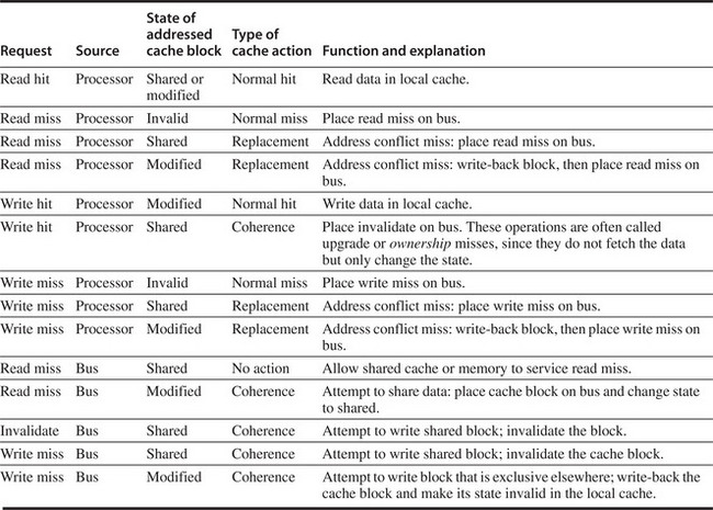
Figure 5.5 The cache coherence mechanism receives requests from both the core’s processor and the shared bus and responds to these based on the type of request, whether it hits or misses in the local cache, and the state of the local cache block specified in the request. The fourth column describes the type of cache action as normal hit or miss (the same as a uniprocessor cache would see), replacement (a uniprocessor cache replacement miss), or coherence (required to maintain cache coherence); a normal or replacement action may cause a coherence action depending on the state of the block in other caches. For read, misses, write misses, or invalidates snooped from the bus, an action is required only if the read or write addresses match a block in the local cache and the block is valid.
When an invalidate or a write miss is placed on the bus, any cores whose private caches have copies of the cache block invalidate it. For a write miss in a write-back cache, if the block is exclusive in just one private cache, that cache also writes back the block; otherwise, the data can be read from the shared cache or memory.
Figure 5.6 shows a finite-state transition diagram for a single private cache block using a write invalidation protocol and a write-back cache. For simplicity, the three states of the protocol are duplicated to represent transitions based on processor requests (on the left, which corresponds to the top half of the table in Figure 5.5), as opposed to transitions based on bus requests (on the right, which corresponds to the bottom half of the table in Figure 5.5). Boldface type is used to distinguish the bus actions, as opposed to the conditions on which a state transition depends. The state in each node represents the state of the selected private cache block specified by the processor or bus request.

Figure 5.6 A write invalidate, cache coherence protocol for a private write-back cache showing the states and state transitions for each block in the cache. The cache states are shown in circles, with any access permitted by the local processor without a state transition shown in parentheses under the name of the state. The stimulus causing a state change is shown on the transition arcs in regular type, and any bus actions generated as part of the state transition are shown on the transition arc in bold. The stimulus actions apply to a block in the private cache, not to a specific address in the cache. Hence, a read miss to a block in the shared state is a miss for that cache block but for a different address. The left side of the diagram shows state transitions based on actions of the processor associated with this cache; the right side shows transitions based on operations on the bus. A read miss in the exclusive or shared state and a write miss in the exclusive state occur when the address requested by the processor does not match the address in the local cache block. Such a miss is a standard cache replacement miss. An attempt to write a block in the shared state generates an invalidate. Whenever a bus transaction occurs, all private caches that contain the cache block specified in the bus transaction take the action dictated by the right half of the diagram. The protocol assumes that memory (or a shared cache) provides data on a read miss for a block that is clean in all local caches. In actual implementations, these two sets of state diagrams are combined. In practice, there are many subtle variations on invalidate protocols, including the introduction of the exclusive unmodified state, as to whether a processor or memory provides data on a miss. In a multicore chip, the shared cache (usually L3, but sometimes L2) acts as the equivalent of memory, and the bus is the bus between the private caches of each core and the shared cache, which in turn interfaces to the memory.
All of the states in this cache protocol would be needed in a uniprocessor cache, where they would correspond to the invalid, valid (and clean), and dirty states. Most of the state changes indicated by arcs in the left half of Figure 5.6 would be needed in a write-back uniprocessor cache, with the exception being the invalidate on a write hit to a shared block. The state changes represented by the arcs in the right half of Figure 5.6 are needed only for coherence and would not appear at all in a uniprocessor cache controller.
As mentioned earlier, there is only one finite-state machine per cache, with stimuli coming either from the attached processor or from the bus. Figure 5.7 shows how the state transitions in the right half of Figure 5.6 are combined with those in the left half of the figure to form a single state diagram for each cache block.
To understand why this protocol works, observe that any valid cache block is either in the shared state in one or more private caches or in the exclusive state in exactly one cache. Any transition to the exclusive state (which is required for a processor to write to the block) requires an invalidate or write miss to be placed on the bus, causing all local caches to make the block invalid. In addition, if some other local cache had the block in exclusive state, that local cache generates a write-back, which supplies the block containing the desired address. Finally, if a read miss occurs on the bus to a block in the exclusive state, the local cache with the exclusive copy changes its state to shared.
The actions in gray in Figure 5.7, which handle read and write misses on the bus, are essentially the snooping component of the protocol. One other property that is preserved in this protocol, and in most other protocols, is that any memory block in the shared state is always up to date in the outer shared cache (L2 or L3, or memory if there is no shared cache), which simplifies the implementation. In fact, it does not matter whether the level out from the private caches is a shared cache or memory; the key is that all accesses from the cores go through that level.

Figure 5.7 Cache coherence state diagram with the state transitions induced by the local processor shown in black and by the bus activities shown in gray. As in Figure 5.6, the activities on a transition are shown in bold.
Although our simple cache protocol is correct, it omits a number of complications that make the implementation much trickier. The most important of these is that the protocol assumes that operations are atomic—that is, an operation can be done in such a way that no intervening operation can occur. For example, the protocol described assumes that write misses can be detected, acquire the bus, and receive a response as a single atomic action. In reality this is not true. In fact, even a read miss might not be atomic; after detecting a miss in the L2 of a multicore, the core must arbitrate for access to the bus connecting to the shared L3. Nonatomic actions introduce the possibility that the protocol can deadlock, meaning that it reaches a state where it cannot continue. We will explore these complications later in this section and when we examine DSM designs.
With multicore processors, the coherence among the processor cores is all implemented on chip, using either a snooping or simple central directory protocol. Many dual-processor chips, including the Intel Xeon and AMD Opteron, supported multichip multiprocessors that could be built by connecting a high-speed interface (called Quickpath or Hypertransport, respectively). These next-level interconnects are not just extensions of the shared bus, but use a different approach for interconnecting multicores.
A multiprocessor built with multiple multicore chips will have a distributed memory architecture and will need an interchip coherency mechanism above and beyond the one within the chip. In most cases, some form of directory scheme is used.
Extensions to the Basic Coherence Protocol
The coherence protocol we have just described is a simple three-state protocol and is often referred to by the first letter of the states, making it a MSI (Modified, Shared, Invalid) protocol. There are many extensions of this basic protocol, which we mentioned in the captions of figures in this section. These extensions are created by adding additional states and transactions, which optimize certain behaviors, possibly resulting in improved performance. Two of the most common extensions are
The next section examines the performance of these protocols for our parallel and multiprogrammed workloads; the value of these extensions to a basic protocol will be clear when we examine the performance. But, before we do that, let’s take a brief look at the limitations on the use of a symmetric memory structure and a snooping coherence scheme.
Limitations in Symmetric Shared-Memory Multiprocessors and Snooping Protocols
As the number of processors in a multiprocessor grows, or as the memory demands of each processor grow, any centralized resource in the system can become a bottleneck. Using the higher bandwidth connection available on-chip and a shared L3 cache, which is faster than memory, designers have managed to support four to eight high-performance cores in a symmetric fashion. Such an approach is unlikely to scale much past eight cores, and it will not work once multiple multicores are combined.
Snooping bandwidth at the caches can also become a problem, since every cache must examine every miss placed on the bus. As we mentioned, duplicating the tags is one solution. Another approach, which has been adopted in some recent multicores, is to place a directory at the level of the outermost cache. The directory explicitly indicates which processor’s caches have copies of every item in the outermost cache. This is the approach Intel uses on the i7 and Xeon 7000 series. Note that the use of this directory does not eliminate the bottleneck due to a shared bus and L3 among the processors, but it is much simpler to implement than the distributed directory schemes that we will examine in Section 5.4.
How can a designer increase the memory bandwidth to support either more or faster processors? To increase the communication bandwidth between processors and memory, designers have used multiple buses as well as interconnection networks, such as crossbars or small point-to-point networks. In such designs, the memory system (either main memory or a shared cache) can be configured into multiple physical banks, so as to boost the effective memory bandwidth while retaining uniform access time to memory. Figure 5.8 shows how such a system might look if it where implemented with a single-chip multicore. Although such an approach might be used to allow more than four cores to be interconnected on a single chip, it does not scale well to a multichip multiprocessor that uses multicore building blocks, since the memory is already attached to the individual multicore chips, rather than centralized.

Figure 5.8 A multicore single-chip multiprocessor with uniform memory access through a banked shared cache and using an interconnection network rather than a bus.
The AMD Opteron represents another intermediate point in the spectrum between a snooping and a directory protocol. Memory is directly connected to each multicore chip, and up to four multicore chips can be connected. The system is a NUMA, since local memory is somewhat faster. The Opteron implements its coherence protocol using the point-to-point links to broadcast up to three other chips. Because the interprocessor links are not shared, the only way a processor can know when an invalid operation has completed is by an explicit acknowledgment. Thus, the coherence protocol uses a broadcast to find potentially shared copies, like a snooping protocol, but uses the acknowledgments to order operations, like a directory protocol. Because local memory is only somewhat faster than remote memory in the Opteron implementation, some software treats an Opteron multiprocessor as having uniform memory access.
A snooping cache coherence protocol can be used without a centralized bus, but still requires that a broadcast be done to snoop the individual caches on every miss to a potentially shared cache block. This cache coherence traffic creates another limit on the scale and the speed of the processors. Because coherence traffic is unaffected by larger caches, faster processors will inevitably overwhelm the network and the ability of each cache to respond to snoop requests from all the other caches. In Section 5.4, we examine directory-based protocols, which eliminate the need for broadcast to all caches on a miss. As processor speeds and the number of cores per processor increase, more designers are likely to opt for such protocols to avoid the broadcast limit of a snooping protocol.
Implementing Snooping Cache Coherence
When we wrote the first edition of this book in 1990, our final “Putting It All Together” was a 30-processor, single-bus multiprocessor using snoop-based coherence; the bus had a capacity of just over 50 MB/sec, which would not be enough bus bandwidth to support even one core of an Intel i7 in 2011! When we wrote the second edition of this book in 1995, the first cache coherence multiprocessors with more than a single bus had recently appeared, and we added an appendix describing the implementation of snooping in a system with multiple buses. In 2011, most multicore processors that support only a single-chip multiprocessor have opted to use a shared bus structure connecting to either a shared memory or a shared cache. In contrast, every multicore multiprocessor system that supports 16 or more cores uses an interconnect other than a single bus, and designers must face the challenge of implementing snooping without the simplification of a bus to serialize events.
As we said earlier, the major complication in actually implementing the snooping coherence protocol we have described is that write and upgrade misses are not atomic in any recent multiprocessor. The steps of detecting a write or upgrade miss, communicating with the other processors and memory, getting the most recent value for a write miss and ensuring that any invalidates are processed, and updating the cache cannot be done as if they took a single cycle.
In a single multicore chip, these steps can be made effectively atomic by arbitrating for the bus to the shared cache or memory first (before changing the cache state) and not releasing the bus until all actions are complete. How can the processor know when all the invalidates are complete? In some multicores, a single line is used to signal when all necessary invalidates have been received and are being processed. Following that signal, the processor that generated the miss can release the bus, knowing that any required actions will be completed before any activity related to the next miss. By holding the bus exclusively during these steps, the processor effectively makes the individual steps atomic.
In a system without a bus, we must find some other method of making the steps in a miss atomic. In particular, we must ensure that two processors that attempt to write the same block at the same time, a situation which is called a race, are strictly ordered: One write is processed and precedes before the next is begun. It does not matter which of two writes in a race wins the race, just that there be only a single winner whose coherence actions are completed first. In a snooping system, ensuring that a race has only one winner is accomplished by using broadcast for all misses as well as some basic properties of the interconnection network. These properties, together with the ability to restart the miss handling of the loser in a race, are the keys to implementing snooping cache coherence without a bus. We explain the details in Appendix I.
It is possible to combine snooping and directories, and several designs use snooping within a multicore and directories among multiple chips or, vice versa, directories within a multicore and snooping among multiple chips.
5.3 Performance of Symmetric Shared-Memory Multiprocessors
In a multicore using a snooping coherence protocol, several different phenomena combine to determine performance. In particular, the overall cache performance is a combination of the behavior of uniprocessor cache miss traffic and the traffic caused by communication, which results in invalidations and subsequent cache misses. Changing the processor count, cache size, and block size can affect these two components of the miss rate in different ways, leading to overall system behavior that is a combination of the two effects.
Appendix B breaks the uniprocessor miss rate into the three C’s classification (capacity, compulsory, and conflict) and provides insight into both application behavior and potential improvements to the cache design. Similarly, the misses that arise from interprocessor communication, which are often called coherence misses, can be broken into two separate sources.
The first source is the so-called true sharing misses that arise from the communication of data through the cache coherence mechanism. In an invalidation-based protocol, the first write by a processor to a shared cache block causes an invalidation to establish ownership of that block. Additionally, when another processor attempts to read a modified word in that cache block, a miss occurs and the resultant block is transferred. Both these misses are classified as true sharing misses since they directly arise from the sharing of data among processors.
The second effect, called false sharing, arises from the use of an invalidation-based coherence algorithm with a single valid bit per cache block. False sharing occurs when a block is invalidated (and a subsequent reference causes a miss) because some word in the block, other than the one being read, is written into. If the word written into is actually used by the processor that received the invalidate, then the reference was a true sharing reference and would have caused a miss independent of the block size. If, however, the word being written and the word read are different and the invalidation does not cause a new value to be communicated, but only causes an extra cache miss, then it is a false sharing miss. In a false sharing miss, the block is shared, but no word in the cache is actually shared, and the miss would not occur if the block size were a single word. The following example makes the sharing patterns clear.
Example
Assume that words x1 and x2 are in the same cache block, which is in the shared state in the caches of both P1 and P2. Assuming the following sequence of events, identify each miss as a true sharing miss, a false sharing miss, or a hit. Any miss that would occur if the block size were one word is designated a true sharing miss.
| Time | P1 | P2 |
|---|---|---|
| 1 | Write x1 | |
| 2 | Read x2 | |
| 3 | Write x1 | |
| 4 | Write x2 | |
| 5 | Read x2 |
Answer
Here are the classifications by time step:
Although we will see the effects of true and false sharing misses in commercial workloads, the role of coherence misses is more significant for tightly coupled applications that share significant amounts of user data. We examine their effects in detail in Appendix I, when we consider the performance of a parallel scientific workload.
A Commercial Workload
In this section, we examine the memory system behavior of a four-processor shared-memory multiprocessor when running a general-purpose commercial workload. The study we examine was done with a four-processor Alpha system in 1998, but it remains the most comprehensive and insightful study of the performance of a multiprocessor for such workloads. The results were collected either on an Alpha-Server 4100 or using a configurable simulator modeled after the AlphaServer 4100. Each processor in the AlphaServer 4100 is an Alpha 21164, which issues up to four instructions per clock and runs at 300 MHz. Although the clock rate of the Alpha processor in this system is considerably slower than processors in systems designed in 2011, the basic structure of the system, consisting of a four-issue processor and a three-level cache hierarchy, is very similar to the multicore Intel i7 and other processors, as shown in Figure 5.9. In particular, the Alpha caches are somewhat smaller, but the miss times are also lower than on an i7. Thus, the behavior of the Alpha system should provide interesting insights into the behavior of modern multicore designs.

Figure 5.9 The characteristics of the cache hierarchy of the Alpha 21164 used in this study and the Intel i7. Although the sizes are larger and the associativity is higher on the i7, the miss penalties are also higher, so the behavior may differ only slightly. For example, from Appendix B, we can estimate the miss rates of the smaller Alpha L1 cache as 4.9% and 3% for the larger i7 L1 cache, so the average L1 miss penalty per reference is 0.34 for the Alpha and 0.30 for the i7. Both systems have a high penalty (125 cycles or more) for a transfer required from a private cache. The i7 also shares its L3 among all the cores.
The workload used for this study consists of three applications:
Figure 5.10 shows the percentages of time spent in user mode, in the kernel, and in the idle loop. The frequency of I/O increases both the kernel time and the idle time (see the OLTP entry, which has the largest I/O-to-computation ratio). AltaVista, which maps the entire search database into memory and has been extensively tuned, shows the least kernel or idle time.

Figure 5.10 The distribution of execution time in the commercial workloads. The OLTP benchmark has the largest fraction of both OS time and processor idle time (which is I/O wait time). The DSS benchmark shows much less OS time, since it does less I/O, but still more than 9% idle time. The extensive tuning of the AltaVista search engine is clear in these measurements. The data for this workload were collected by Barroso, Gharachorloo, and Bugnion [1998] on a four-processor AlphaServer 4100.
Performance Measurements of the Commercial Workload
We start by looking at the overall processor execution for these benchmarks on the four-processor system; as discussed on page 367, these benchmarks include substantial I/O time, which is ignored in the processor time measurements. We group the six DSS queries as a single benchmark, reporting the average behavior. The effective CPI varies widely for these benchmarks, from a CPI of 1.3 for the AltaVista Web search, to an average CPI of 1.6 for the DSS workload, to 7.0 for the OLTP workload. Figure 5.11 shows how the execution time breaks down into instruction execution, cache and memory system access time, and other stalls (which are primarily pipeline resource stalls but also include translation lookaside buffer (TLB) and branch mispredict stalls). Although the performance of the DSS and AltaVista workloads is reasonable, the performance of the OLTP workload is very poor, due to a poor performance of the memory hierarchy.

Figure 5.11 The execution time breakdown for the three programs (OLTP, DSS, and AltaVista) in the commercial workload. The DSS numbers are the average across six different queries. The CPI varies widely from a low of 1.3 for AltaVista, to 1.61 for the DSS queries, to 7.0 for OLTP. (Individually, the DSS queries show a CPI range of 1.3 to 1.9.) “Other stalls” includes resource stalls (implemented with replay traps on the 21164), branch mispredict, memory barrier, and TLB misses. For these benchmarks, resource-based pipeline stalls are the dominant factor. These data combine the behavior of user and kernel accesses. Only OLTP has a significant fraction of kernel accesses, and the kernel accesses tend to be better behaved than the user accesses! All the measurements shown in this section were collected by Barroso, Gharachorloo, and Bugnion [1998].
Since the OLTP workload demands the most from the memory system with large numbers of expensive L3 misses, we focus on examining the impact of L3 cache size, processor count, and block size on the OLTP benchmark. Figure 5.12 shows the effect of increasing the cache size, using two-way set associative caches, which reduces the large number of conflict misses. The execution time is improved as the L3 cache grows due to the reduction in L3 misses. Surprisingly, almost all of the gain occurs in going from 1 to 2 MB, with little additional gain beyond that, despite the fact that cache misses are still a cause of significant performance loss with 2 MB and 4 MB caches. The question is, Why?

Figure 5.12 The relative performance of the OLTP workload as the size of the L3 cache, which is set as two-way set associative, grows from 1 MB to 8 MB. The idle time also grows as cache size is increased, reducing some of the performance gains. This growth occurs because, with fewer memory system stalls, more server processes are needed to cover the I/O latency. The workload could be retuned to increase the computation/communication balance, holding the idle time in check. The PAL code is a set of sequences of specialized OS-level instructions executed in privileged mode; an example is the TLB miss handler.
To better understand the answer to this question, we need to determine what factors contribute to the L3 miss rate and how they change as the L3 cache grows. Figure 5.13 shows these data, displaying the number of memory access cycles contributed per instruction from five sources. The two largest sources of L3 memory access cycles with a 1 MB L3 are instruction and capacity/conflict misses. With a larger L3, these two sources shrink to be minor contributors. Unfortunately, the compulsory, false sharing, and true sharing misses are unaffected by a larger L3. Thus, at 4 MB and 8 MB, the true sharing misses generate the dominant fraction of the misses; the lack of change in true sharing misses leads to the limited reductions in the overall miss rate when increasing the L3 cache size beyond 2 MB.

Figure 5.13 The contributing causes of memory access cycle shift as the cache size is increased. The L3 cache is simulated as two-way set associative.
Increasing the cache size eliminates most of the uniprocessor misses while leaving the multiprocessor misses untouched. How does increasing the processor count affect different types of misses? Figure 5.14 shows these data assuming a base configuration with a 2 MB, two-way set associative L3 cache. As we might expect, the increase in the true sharing miss rate, which is not compensated for by any decrease in the uniprocessor misses, leads to an overall increase in the memory access cycles per instruction.

Figure 5.14 The contribution to memory access cycles increases as processor count increases primarily due to increased true sharing. The compulsory misses slightly increase since each processor must now handle more compulsory misses.
The final question we examine is whether increasing the block size—which should decrease the instruction and cold miss rate and, within limits, also reduce the capacity/conflict miss rate and possibly the true sharing miss rate—is helpful for this workload. Figure 5.15 shows the number of misses per 1000 instructions as the block size is increased from 32 to 256 bytes. Increasing the block size from 32 to 256 bytes affects four of the miss rate components:

Figure 5.15 The number of misses per 1000 instructions drops steadily as the block size of the L3 cache is increased, making a good case for an L3 block size of at least 128 bytes. The L3 cache is 2 MB, two-way set associative.
The lack of a significant effect on the instruction miss rate is startling. If there were an instruction-only cache with this behavior, we would conclude that the spatial locality is very poor. In the case of a mixed L2 cache, other effects such as instruction-data conflicts may also contribute to the high instruction cache miss rate for larger blocks. Other studies have documented the low spatial locality in the instruction stream of large database and OLTP workloads, which have lots of short basic blocks and special-purpose code sequences. Based on these data, the miss penalty for a larger block size L3 to perform as well as the 32-byte block size L3 can be expressed as a multiplier on the 32-byte block size penalty:
| Block size | Miss penalty relative to 32-byte block miss penalty |
|---|---|
| 64 bytes | 1.19 |
| 128 bytes | 1.36 |
| 256 bytes | 1.52 |
With modern DDR SDRAMs that make block access fast, these numbers seem attainable, especially at the 128 byte block size. Of course, we must also worry about the effects of the increased traffic to memory and possible contention for the memory with other cores. This latter effect may easily negate the gains obtained from improving the performance of a single processor.
A Multiprogramming and OS Workload
Our next study is a multiprogrammed workload consisting of both user activity and OS activity. The workload used is two independent copies of the compile phases of the Andrew benchmark, a benchmark that emulates a software development environment. The compile phase consists of a parallel version of the Unix “make” command executed using eight processors. The workload runs for 5.24 seconds on eight processors, creating 203 processes and performing 787 disk requests on three different file systems. The workload is run with 128 MB of memory, and no paging activity takes place.
The workload has three distinct phases: compiling the benchmarks, which involves substantial compute activity; installing the object files in a library; and removing the object files. The last phase is completely dominated by I/O, and only two processes are active (one for each of the runs). In the middle phase, I/O also plays a major role, and the processor is largely idle. The overall workload is much more system and I/O intensive than the highly tuned commercial workload.
For the workload measurements, we assume the following memory and I/O systems:
Figure 5.16 shows how the execution time breaks down for the eight processors using the parameters just listed. Execution time is broken down into four components:

Figure 5.16 The distribution of execution time in the multiprogrammed parallel “make” workload. The high fraction of idle time is due to disk latency when only one of the eight processors is active. These data and the subsequent measurements for this workload were collected with the SimOS system [Rosenblum et al. 1995]. The actual runs and data collection were done by M. Rosenblum, S. Herrod, and E. Bugnion of Stanford University.
This multiprogramming workload has a significant instruction cache performance loss, at least for the OS. The instruction cache miss rate in the OS for a 64-byte block size, two-way set associative cache varies from 1.7% for a 32 KB cache to 0.2% for a 256 KB cache. User-level instruction cache misses are roughly one-sixth of the OS rate, across the variety of cache sizes. This partially accounts for the fact that, although the user code executes nine times as many instructions as the kernel, those instructions take only about four times as long as the smaller number of instructions executed by the kernel.
Performance of the Multiprogramming and OS Workload
In this subsection, we examine the cache performance of the multiprogrammed workload as the cache size and block size are changed. Because of differences between the behavior of the kernel and that of the user processes, we keep these two components separate. Remember, though, that the user processes execute more than eight times as many instructions, so that the overall miss rate is determined primarily by the miss rate in user code, which, as we will see, is often one-fifth of the kernel miss rate.
Although the user code executes more instructions, the behavior of the operating system can cause more cache misses than the user processes for two reasons beyond larger code size and lack of locality. First, the kernel initializes all pages before allocating them to a user, which significantly increases the compulsory component of the kernel’s miss rate. Second, the kernel actually shares data and thus has a nontrivial coherence miss rate. In contrast, user processes cause coherence misses only when the process is scheduled on a different processor, and this component of the miss rate is small.
Figure 5.17 shows the data miss rate versus data cache size and versus block size for the kernel and user components. Increasing the data cache size affects the user miss rate more than it affects the kernel miss rate. Increasing the block size has beneficial effects for both miss rates, since a larger fraction of the misses arise from compulsory and capacity, both of which can be potentially improved with larger block sizes. Since coherence misses are relatively rarer, the negative effects of increasing block size are small. To understand why the kernel and user processes behave differently, we can look at how the kernel misses behave.

Figure 5.17 The data miss rates for the user and kernel components behave differently for increases in the L1 data cache size (on the left) versus increases in the L1 data cache block size (on the right). Increasing the L1 data cache from 32 KB to 256 KB (with a 32-byte block) causes the user miss rate to decrease proportionately more than the kernel miss rate: the user-level miss rate drops by almost a factor of 3, while the kernel-level miss rate drops only by a factor of 1.3. The miss rate for both user and kernel components drops steadily as the L1 block size is increased (while keeping the L1 cache at 32 KB). In contrast to the effects of increasing the cache size, increasing the block size improves the kernel miss rate more significantly (just under a factor of 4 for the kernel references when going from 16-byte to 128-byte blocks versus just under a factor of 3 for the user references).
Figure 5.18 shows the variation in the kernel misses versus increases in cache size and in block size. The misses are broken into three classes: compulsory misses, coherence misses (from both true and false sharing), and capacity/conflict misses (which include misses caused by interference between the OS and the user process and between multiple user processes). Figure 5.18 confirms that, for the kernel references, increasing the cache size reduces only the uniprocessor capacity/conflict miss rate. In contrast, increasing the block size causes a reduction in the compulsory miss rate. The absence of large increases in the coherence miss rate as block size is increased means that false sharing effects are probably insignificant, although such misses may be offsetting some of the gains from reducing the true sharing misses.

Figure 5.18 The components of the kernel data miss rate change as the L1 data cache size is increased from 32 KB to 256 KB, when the multiprogramming workload is run on eight processors. The compulsory miss rate component stays constant, since it is unaffected by cache size. The capacity component drops by more than a factor of 2, while the coherence component nearly doubles. The increase in coherence misses occurs because the probability of a miss being caused by an invalidation increases with cache size, since fewer entries are bumped due to capacity. As we would expect, the increasing block size of the L1 data cache substantially reduces the compulsory miss rate in the kernel references. It also has a significant impact on the capacity miss rate, decreasing it by a factor of 2.4 over the range of block sizes. The increased block size has a small reduction in coherence traffic, which appears to stabilize at 64 bytes, with no change in the coherence miss rate in going to 128-byte lines. Because there are no significant reductions in the coherence miss rate as the block size increases, the fraction of the miss rate due to coherence grows from about 7% to about 15%.
If we examine the number of bytes needed per data reference, as in Figure 5.19, we see that the kernel has a higher traffic ratio that grows with block size. It is easy to see why this occurs: When going from a 16-byte block to a 128-byte block, the miss rate drops by about 3.7, but the number of bytes transferred per miss increases by 8, so the total miss traffic increases by just over a factor of 2. The user program also more than doubles as the block size goes from 16 to 128 bytes, but it starts out at a much lower level.

Figure 5.19 The number of bytes needed per data reference grows as block size is increased for both the kernel and user components. It is interesting to compare this chart against the data on scientific programs shown in Appendix I.
For the multiprogrammed workload, the OS is a much more demanding user of the memory system. If more OS or OS-like activity is included in the workload, and the behavior is similar to what was measured for this workload, it will become very difficult to build a sufficiently capable memory system. One possible route to improving performance is to make the OS more cache aware, through either better programming environments or through programmer assistance. For example, the OS reuses memory for requests that arise from different system calls. Despite the fact that the reused memory will be completely overwritten, the hardware, not recognizing this, will attempt to preserve coherency and the possibility that some portion of a cache block may be read, even if it is not. This behavior is analogous to the reuse of stack locations on procedure invocations. The IBM Power series has support to allow the compiler to indicate this type of behavior on procedure invocations, and the newest AMD processors have similar support. It is harder to detect such behavior by the OS, and doing so may require programmer assistance, but the payoff is potentially even greater.
OS and commercial workloads pose tough challenges for multiprocessor memory systems, and unlike scientific applications, which we examine in Appendix I, they are less amenable to algorithmic or compiler restructuring. As the number of cores increases predicting the behavior of such applications is likely to get more difficult. Emulation or simulation methodologies that allow the simulation of hundreds of cores with large applications (including operating systems) will be crucial to maintaining an analytical and quantitative approach to design.
5.4 Distributed Shared-Memory and Directory-Based Coherence
As we saw in Section 5.2, a snooping protocol requires communication with all caches on every cache miss, including writes of potentially shared data. The absence of any centralized data structure that tracks the state of the caches is both the fundamental advantage of a snooping-based scheme, since it allows it to be inexpensive, as well as its Achilles’ heel when it comes to scalability.
For example, consider a multiprocessor composed of four 4-core multicores capable of sustaining one data reference per clock and a 4 GHz clock. From the data in Section I.5 of Appendix I, we can see that the applications may require 4 GB/sec to 170 GB/sec of bus bandwidth. Although the caches in those experiments are small, most of the traffic is coherence traffic, which is unaffected by cache size. Although a modern bus might accommodate 4 GB/sec, 170 GB/sec is far beyond the capability of any bus-based system. In the last few years, the development of multicore processors forced all designers to shift to some form of distributed memory to support the bandwidth demands of the individual processors.
We can increase the memory bandwidth and interconnection bandwidth by distributing the memory, as shown in Figure 5.2 on page 348; this immediately separates local memory traffic from remote memory traffic, reducing the bandwidth demands on the memory system and on the interconnection network. Unless we eliminate the need for the coherence protocol to broadcast on every cache miss, distributing the memory will gain us little.
As we mentioned earlier, the alternative to a snooping-based coherence protocol is a directory protocol. A directory keeps the state of every block that may be cached. Information in the directory includes which caches (or collections of caches) have copies of the block, whether it is dirty, and so on. Within a multicore with a shared outermost cache (say, L3), it is easy to implement a directory scheme: Simply keep a bit vector of the size equal to the number of cores for each L3 block. The bit vector indicates which private caches may have copies of a block in L3, and invalidations are only sent to those caches. This works perfectly for a single multicore if L3 is inclusive, and this scheme is the one used in the Intel i7.
The solution of a single directory used in a multicore is not scalable, even though it avoids broadcast. The directory must be distributed, but the distribution must be done in a way that the coherence protocol knows where to find the directory information for any cached block of memory. The obvious solution is to distribute the directory along with the memory, so that different coherence requests can go to different directories, just as different memory requests go to different memories. A distributed directory retains the characteristic that the sharing status of a block is always in a single known location. This property, together with the maintenance of information that says what other nodes may be caching the block, is what allows the coherence protocol to avoid broadcast. Figure 5.20 shows how our distributed-memory multiprocessor looks with the directories added to each node.

Figure 5.20 A directory is added to each node to implement cache coherence in a distributed-memory multiprocessor. In this case, a node is shown as a single multicore chip, and the directory information for the associated memory may reside either on or off the multicore. Each directory is responsible for tracking the caches that share the memory addresses of the portion of memory in the node. The coherence mechanism would handle both the maintenance of the directory information and any coherence actions needed within the multicore node.
The simplest directory implementations associate an entry in the directory with each memory block. In such implementations, the amount of information is proportional to the product of the number of memory blocks (where each block is the same size as the L2 or L3 cache block) times the number of nodes, where a node is a single multicore processor or a small collection of processors that implements coherence internally. This overhead is not a problem for multiprocessors with less than a few hundred processors (each of which might be a multicore) because the directory overhead with a reasonable block size will be tolerable. For larger multiprocessors, we need methods to allow the directory structure to be efficiently scaled, but only supercomputer-sized systems need to worry about this.
Directory-Based Cache Coherence Protocols: The Basics
Just as with a snooping protocol, there are two primary operations that a directory protocol must implement: handling a read miss and handling a write to a shared, clean cache block. (Handling a write miss to a block that is currently shared is a simple combination of these two.) To implement these operations, a directory must track the state of each cache block. In a simple protocol, these states could be the following:
In addition to tracking the state of each potentially shared memory block, we must track which nodes have copies of that block, since those copies will need to be invalidated on a write. The simplest way to do this is to keep a bit vector for each memory block. When the block is shared, each bit of the vector indicates whether the corresponding processor chip (which is likely a multicore) has a copy of that block. We can also use the bit vector to keep track of the owner of the block when the block is in the exclusive state. For efficiency reasons, we also track the state of each cache block at the individual caches.
The states and transitions for the state machine at each cache are identical to what we used for the snooping cache, although the actions on a transition are slightly different. The processes of invalidating and locating an exclusive copy of a data item are different, since they both involve communication between the requesting node and the directory and between the directory and one or more remote nodes. In a snooping protocol, these two steps are combined through the use of a broadcast to all the nodes.
Before we see the protocol state diagrams, it is useful to examine a catalog of the message types that may be sent between the processors and the directories for the purpose of handling misses and maintaining coherence. Figure 5.21 shows the types of messages sent among nodes. The local node is the node where a request originates. The home node is the node where the memory location and the directory entry of an address reside. The physical address space is statically distributed, so the node that contains the memory and directory for a given physical address is known. For example, the high-order bits may provide the node number, while the low-order bits provide the offset within the memory on that node. The local node may also be the home node. The directory must be accessed when the home node is the local node, since copies may exist in yet a third node, called a remote node.

Figure 5.21 The possible messages sent among nodes to maintain coherence, along with the source and destination node, the contents (where P = requesting node number, A = requested address, and D = data contents), and the function of the message. The first three messages are requests sent by the local node to the home. The fourth through sixth messages are messages sent to a remote node by the home when the home needs the data to satisfy a read or write miss request. Data value replies are used to send a value from the home node back to the requesting node. Data value write-backs occur for two reasons: when a block is replaced in a cache and must be written back to its home memory, and also in reply to fetch or fetch/invalidate messages from the home. Writing back the data value whenever the block becomes shared simplifies the number of states in the protocol, since any dirty block must be exclusive and any shared block is always available in the home memory.
A remote node is the node that has a copy of a cache block, whether exclusive (in which case it is the only copy) or shared. A remote node may be the same as either the local node or the home node. In such cases, the basic protocol does not change, but interprocessor messages may be replaced with intraprocessor messages.
In this section, we assume a simple model of memory consistency. To minimize the type of messages and the complexity of the protocol, we make an assumption that messages will be received and acted upon in the same order they are sent. This assumption may not be true in practice and can result in additional complications, some of which we address in Section 5.6 when we discuss memory consistency models. In this section, we use this assumption to ensure that invalidates sent by a node are honored before new messages are transmitted, just as we assumed in the discussion of implementing snooping protocols. As we did in the snooping case, we omit some details necessary to implement the coherence protocol. In particular, the serialization of writes and knowing that the invalidates for a write have completed are not as simple as in the broadcast-based snooping mechanism. Instead, explicit acknowledgments are required in response to write misses and invalidate requests. We discuss these issues in more detail in Appendix I.
An Example Directory Protocol
The basic states of a cache block in a directory-based protocol are exactly like those in a snooping protocol, and the states in the directory are also analogous to those we showed earlier. Thus, we can start with simple state diagrams that show the state transitions for an individual cache block and then examine the state diagram for the directory entry corresponding to each block in memory. As in the snooping case, these state transition diagrams do not represent all the details of a coherence protocol; however, the actual controller is highly dependent on a number of details of the multiprocessor (message delivery properties, buffering structures, and so on). In this section, we present the basic protocol state diagrams. The knotty issues involved in implementing these state transition diagrams are examined in Appendix I.
Figure 5.22 shows the protocol actions to which an individual cache responds. We use the same notation as in the last section, with requests coming from outside the node in gray and actions in bold. The state transitions for an individual cache are caused by read misses, write misses, invalidates, and data fetch requests; Figure 5.22 shows these operations. An individual cache also generates read miss, write miss, and invalidate messages that are sent to the home directory. Read and write misses require data value replies, and these events wait for replies before changing state. Knowing when invalidates complete is a separate problem and is handled separately.

Figure 5.22 State transition diagram for an individual cache block in a directory-based system. Requests by the local processor are shown in black, and those from the home directory are shown in gray. The states are identical to those in the snooping case, and the transactions are very similar, with explicit invalidate and write-back requests replacing the write misses that were formerly broadcast on the bus. As we did for the snooping controller, we assume that an attempt to write a shared cache block is treated as a miss; in practice, such a transaction can be treated as an ownership request or upgrade request and can deliver ownership without requiring that the cache block be fetched.
The operation of the state transition diagram for a cache block in Figure 5.22 is essentially the same as it is for the snooping case: The states are identical, and the stimulus is almost identical. The write miss operation, which was broadcast on the bus (or other network) in the snooping scheme, is replaced by the data fetch and invalidate operations that are selectively sent by the directory controller. Like the snooping protocol, any cache block must be in the exclusive state when it is written, and any shared block must be up to date in memory. In many multicore processors, the outermost level in the processor cache is shared among the cores (as is the L3 in the Intel i7, the AMD Opteron, and the IBM Power7), and hardware at that level maintains coherence among the private caches of each core on the same chip, using either an internal directory or snooping. Thus, the on-chip multicore coherence mechanism can be used to extend coherence among a larger set of processors by simply interfacing to the outermost shared cache. Because this interface is at L3, contention between the processor and coherence requests is less of an issue, and duplicating the tags could be avoided.
In a directory-based protocol, the directory implements the other half of the coherence protocol. A message sent to a directory causes two different types of actions: updating the directory state and sending additional messages to satisfy the request. The states in the directory represent the three standard states for a block; unlike in a snooping scheme, however, the directory state indicates the state of all the cached copies of a memory block, rather than for a single cache block.
The memory block may be uncached by any node, cached in multiple nodes and readable (shared), or cached exclusively and writable in exactly one node. In addition to the state of each block, the directory must track the set of nodes that have a copy of a block; we use a set called Sharers to perform this function. In multiprocessors with fewer than 64 nodes (each of which may represent four to eight times as many processors), this set is typically kept as a bit vector. Directory requests need to update the set Sharers and also read the set to perform invalidations.
Figure 5.23 shows the actions taken at the directory in response to messages received. The directory receives three different requests: read miss, write miss, and data write-back. The messages sent in response by the directory are shown in bold, while the updating of the set Sharers is shown in bold italics. Because all the stimulus messages are external, all actions are shown in gray. Our simplified protocol assumes that some actions are atomic, such as requesting a value and sending it to another node; a realistic implementation cannot use this assumption.

Figure 5.23 The state transition diagram for the directory has the same states and structure as the transition diagram for an individual cache. All actions are in gray because they are all externally caused. Bold indicates the action taken by the directory in response to the request.
To understand these directory operations, let’s examine the requests received and actions taken state by state. When a block is in the uncached state, the copy in memory is the current value, so the only possible requests for that block are
When the block is in the shared state, the memory value is up to date, so the same two requests can occur:
When the block is in the exclusive state, the current value of the block is held in a cache on the node identified by the set Sharers (the owner), so there are three possible directory requests:
This state transition diagram in Figure 5.23 is a simplification, just as it was in the snooping cache case. In the case of a directory, as well as a snooping scheme implemented with a network other than a bus, our protocols will need to deal with nonatomic memory transactions. Appendix I explores these issues in depth.
The directory protocols used in real multiprocessors contain additional optimizations. In particular, in this protocol when a read or write miss occurs for a block that is exclusive, the block is first sent to the directory at the home node. From there it is stored into the home memory and also sent to the original requesting node. Many of the protocols in use in commercial multiprocessors forward the data from the owner node to the requesting node directly (as well as performing the write-back to the home). Such optimizations often add complexity by increasing the possibility of deadlock and by increasing the types of messages that must be handled.
Implementing a directory scheme requires solving most of the same challenges we discussed for snooping protocols beginning on page 365. There are, however, new and additional problems, which we describe in Appendix I. In Section 5.8, we briefly describe how modern multicores extend coherence beyond a single chip. The combinations of multichip coherence and multicore coherence include all four possibilities of snooping/snooping (AMD Opteron), snooping/directory, directory/snooping, and directory/directory!
5.5 Synchronization: The Basics
Synchronization mechanisms are typically built with user-level software routines that rely on hardware-supplied synchronization instructions. For smaller multiprocessors or low-contention situations, the key hardware capability is an uninterruptible instruction or instruction sequence capable of atomically retrieving and changing a value. Software synchronization mechanisms are then constructed using this capability. In this section, we focus on the implementation of lock and unlock synchronization operations. Lock and unlock can be used straight-forwardly to create mutual exclusion, as well as to implement more complex synchronization mechanisms.
In high-contention situations, synchronization can become a performance bottleneck because contention introduces additional delays and because latency is potentially greater in such a multiprocessor. We discuss how the basic synchronization mechanisms of this section can be extended for large processor counts in Appendix I.
Basic Hardware Primitives
The key ability we require to implement synchronization in a multiprocessor is a set of hardware primitives with the ability to atomically read and modify a memory location. Without such a capability, the cost of building basic synchronization primitives will be too high and will increase as the processor count increases. There are a number of alternative formulations of the basic hardware primitives, all of which provide the ability to atomically read and modify a location, together with some way to tell if the read and write were performed atomically. These hardware primitives are the basic building blocks that are used to build a wide variety of user-level synchronization operations, including things such as locks and barriers. In general, architects do not expect users to employ the basic hardware primitives, but instead expect that the primitives will be used by system programmers to build a synchronization library, a process that is often complex and tricky. Let’s start with one such hardware primitive and show how it can be used to build some basic synchronization operations.
One typical operation for building synchronization operations is the atomic exchange, which interchanges a value in a register for a value in memory. To see how to use this to build a basic synchronization operation, assume that we want to build a simple lock where the value 0 is used to indicate that the lock is free and 1 is used to indicate that the lock is unavailable. A processor tries to set the lock by doing an exchange of 1, which is in a register, with the memory address corresponding to the lock. The value returned from the exchange instruction is 1 if some other processor had already claimed access and 0 otherwise. In the latter case, the value is also changed to 1, preventing any competing exchange from also retrieving a 0.
For example, consider two processors that each try to do the exchange simultaneously: This race is broken since exactly one of the processors will perform the exchange first, returning 0, and the second processor will return 1 when it does the exchange. The key to using the exchange (or swap) primitive to implement synchronization is that the operation is atomic: The exchange is indivisible, and two simultaneous exchanges will be ordered by the write serialization mechanisms. It is impossible for two processors trying to set the synchronization variable in this manner to both think they have simultaneously set the variable.
There are a number of other atomic primitives that can be used to implement synchronization. They all have the key property that they read and update a memory value in such a manner that we can tell whether or not the two operations executed atomically. One operation, present in many older multiprocessors, is test-and-set, which tests a value and sets it if the value passes the test. For example, we could define an operation that tested for 0 and set the value to 1, which can be used in a fashion similar to how we used atomic exchange. Another atomic synchronization primitive is fetch-and-increment: It returns the value of a memory location and atomically increments it. By using the value 0 to indicate that the synchronization variable is unclaimed, we can use fetch-and-increment, just as we used exchange. There are other uses of operations like fetch-and-increment, which we will see shortly.
Implementing a single atomic memory operation introduces some challenges, since it requires both a memory read and a write in a single, uninterruptible instruction. This requirement complicates the implementation of coherence, since the hardware cannot allow any other operations between the read and the write, and yet must not deadlock.
An alternative is to have a pair of instructions where the second instruction returns a value from which it can be deduced whether the pair of instructions was executed as if the instructions were atomic. The pair of instructions is effectively atomic if it appears as if all other operations executed by any processor occurred before or after the pair. Thus, when an instruction pair is effectively atomic, no other processor can change the value between the instruction pair.
The pair of instructions includes a special load called a load linked or load locked and a special store called a store conditional. These instructions are used in sequence: If the contents of the memory location specified by the load linked are changed before the store conditional to the same address occurs, then the store conditional fails. If the processor does a context switch between the two instructions, then the store conditional also fails. The store conditional is defined to return 1 if it was successful and a 0 otherwise. Since the load linked returns the initial value and the store conditional returns 1 only if it succeeds, the following sequence implements an atomic exchange on the memory location specified by the contents of R1:

At the end of this sequence the contents of R4 and the memory location specified by R1 have been atomically exchanged (ignoring any effect from delayed branches). Anytime a processor intervenes and modifies the value in memory between the LL and SC instructions, the SC returns 0 in R3, causing the code sequence to try again.
An advantage of the load linked/store conditional mechanism is that it can be used to build other synchronization primitives. For example, here is an atomic fetch-and-increment:

These instructions are typically implemented by keeping track of the address specified in the LL instruction in a register, often called the link register. If an interrupt occurs, or if the cache block matching the address in the link register is invalidated (for example, by another SC), the link register is cleared. The SC instruction simply checks that its address matches that in the link register. If so, the SC succeeds; otherwise, it fails. Since the store conditional will fail after either another attempted store to the load linked address or any exception, care must be taken in choosing what instructions are inserted between the two instructions. In particular, only register-register instructions can safely be permitted; otherwise, it is possible to create deadlock situations where the processor can never complete the SC. In addition, the number of instructions between the load linked and the store conditional should be small to minimize the probability that either an unrelated event or a competing processor causes the store conditional to fail frequently.
Implementing Locks Using Coherence
Once we have an atomic operation, we can use the coherence mechanisms of a multiprocessor to implement spin locks—locks that a processor continuously tries to acquire, spinning around a loop until it succeeds. Spin locks are used when programmers expect the lock to be held for a very short amount of time and when they want the process of locking to be low latency when the lock is available. Because spin locks tie up the processor, waiting in a loop for the lock to become free, they are inappropriate in some circumstances.
The simplest implementation, which we would use if there were no cache coherence, would be to keep the lock variables in memory. A processor could continually try to acquire the lock using an atomic operation, say, atomic exchange from page 387, and test whether the exchange returned the lock as free. To release the lock, the processor simply stores the value 0 to the lock. Here is the code sequence to lock a spin lock whose address is in R1 using an atomic exchange:

If our multiprocessor supports cache coherence, we can cache the locks using the coherence mechanism to maintain the lock value coherently. Caching locks has two advantages. First, it allows an implementation where the process of “spinning” (trying to test and acquire the lock in a tight loop) could be done on a local cached copy rather than requiring a global memory access on each attempt to acquire the lock. The second advantage comes from the observation that there is often locality in lock accesses; that is, the processor that used the lock last will use it again in the near future. In such cases, the lock value may reside in the cache of that processor, greatly reducing the time to acquire the lock.
Obtaining the first advantage—being able to spin on a local cached copy rather than generating a memory request for each attempt to acquire the lock—requires a change in our simple spin procedure. Each attempt to exchange in the loop directly above requires a write operation. If multiple processors are attempting to get the lock, each will generate the write. Most of these writes will lead to write misses, since each processor is trying to obtain the lock variable in an exclusive state.
Thus, we should modify our spin lock procedure so that it spins by doing reads on a local copy of the lock until it successfully sees that the lock is available. Then it attempts to acquire the lock by doing a swap operation. A proces-sor first reads the lock variable to test its state. A processor keeps reading and testing until the value of the read indicates that the lock is unlocked. The processor then races against all other processes that were similarly “spin waiting” to see who can lock the variable first. All processes use a swap instruction that reads the old value and stores a 1 into the lock variable. The single winner will see the 0, and the losers will see a 1 that was placed there by the winner. (The losers will continue to set the variable to the locked value, but that doesn’t matter.) The win-ning processor executes the code after the lock and, when finished, stores a 0 into the lock variable to release the lock, which starts the race all over again. Here is the code to perform this spin lock (remember that 0 is unlocked and 1 is locked):

Let’s examine how this “spin lock” scheme uses the cache coherence mechanisms. Figure 5.24 shows the processor and bus or directory operations for multiple processes try-ing to lock a variable using an atomic swap. Once the processor with the lock stores a 0 into the lock, all other caches are invalidated and must fetch the new value to update their copy of the lock. One such cache gets the copy of the unlocked value (0) first and performs the swap. When the cache miss of other processors is satisfied, they find that the variable is already locked, so they must return to testing and spinning.

Figure 5.24 Cache coherence steps and bus traffic for three processors, P0, P1, and P2. This figure assumes write invalidate coherence. P0 starts with the lock (step 1), and the value of the lock is 1 (i.e., locked); it is initially exclusive and owned by P0 before step 1 begins. P0 exits and unlocks the lock (step 2). P1 and P2 race to see which reads the unlocked value during the swap (steps 3 to 5). P2 wins and enters the critical section (steps 6 and 7), while P1’s attempt fails so it starts spin waiting (steps 7 and 8). In a real system, these events will take many more than 8 clock ticks, since acquiring the bus and replying to misses take much longer. Once step 8 is reached, the process can repeat with P2, eventually getting exclusive access and setting the lock to 0.
This example shows another advantage of the load linked/store conditional primitives: The read and write operations are explicitly separated. The load linked need not cause any bus traffic. This fact allows the following simple code sequence, which has the same characteristics as the optimized version using exchange (R1 has the address of the lock, the LL has replaced the LD, and the SC has replaced the EXCH):

The first branch forms the spinning loop; the second branch resolves races when two processors see the lock available simultaneously.
5.6 Models of Memory Consistency: An Introduction
Cache coherence ensures that multiple processors see a consistent view of memory. It does not answer the question of how consistent the view of memory must be. By “how consistent” we are really asking when must a processor see a value that has been updated by another processor? Since processors communicate through shared variables (used both for data values and for synchronization), the question boils down to this: In what order must a processor observe the data writes of another processor? Since the only way to “observe the writes of another processor” is through reads, the question becomes what properties must be enforced among reads and writes to different locations by different processors?
Although the question of how consistent memory must be seems simple, it is remarkably complicated, as we can see with a simple example. Here are two code segments from processes P1 and P2, shown side by side:

Assume that the processes are running on different processors, and that locations A and B are originally cached by both processors with the initial value of 0. If writes always take immediate effect and are immediately seen by other processors, it will be impossible for both if statements (labeled L1 and L2) to evaluate their conditions as true, since reaching the if statement means that either A or B must have been assigned the value 1. But suppose the write invalidate is delayed, and the processor is allowed to continue during this delay. Then, it is possible that both P1 and P2 have not seen the invalidations for B and A (respectively) before they attempt to read the values. The question now is should this behavior be allowed, and, if so, under what conditions?
The most straightforward model for memory consistency is called sequential consistency. Sequential consistency requires that the result of any execution be the same as if the memory accesses executed by each processor were kept in order and the accesses among different processors were arbitrarily interleaved. Sequential consistency eliminates the possibility of some nonobvious execution in the previous example because the assignments must be completed before the if statements are initiated.
The simplest way to implement sequen-tial consistency is to require a processor to delay the completion of any memory access until all the invalidations caused by that access are completed. Of course, it is equally effective to delay the next memory access until the previous one is completed. Remember that memory consistency involves operations among different variables: The two accesses that must be ordered are actually to different memory locations. In our example, we must delay the read of A or B (A == 0 or B == 0) until the previous write has completed (B = 1 or A = 1). Under sequential consistency, we cannot, for example, simply place the write in a write buffer and continue with the read.
Although sequential consistency presents a simple programming paradigm, it reduces potential performance, especially in a multiprocessor with a large number of processors or long inter-connect delays, as we can see in the following example.
Example
Suppose we have a processor where a write miss takes 50 cycles to establish ownership, 10 cycles to issue each invalidate after ownership is established, and 80 cycles for an invalidate to complete and be acknowledged once it is issued. Assuming that four other processors share a cache block, how long does a write miss stall the writing processor if the processor is sequentially consistent? Assume that the invalidates must be explicitly acknowledged before the coherence controller knows they are completed. Suppose we could continue executing after obtaining ownership for the write miss without waiting for the invalidates; how long would the write take?
Answer
When we wait for invalidates, each write takes the sum of the ownership time plus the time to complete the invalidates. Since the invalidates can overlap, we need only worry about the last one, which starts 10 + 10 + 10 + 10 = 40 cycles after ownership is established. Hence, the total time for the write is 50 + 40 + 80 = 170 cycles. In comparison, the ownership time is only 50 cycles. With appropriate write buffer implementations, it is even possible to continue before ownership is established.
To provide better performance, researchers and architects have explored two different routes. First, they developed ambitious implementations that preserve sequential consistency but use latency-hiding techniques to reduce the penalty; we discuss these in Section 5.7. Second, they developed less restrictive memory consistency models that allow for faster hardware. Such models can affect how the programmer sees the multiprocessor, so before we discuss these less restrictive models, let’s look at what the programmer expects.
The Programmer’s View
Although the sequential consistency model has a performance disadvantage, from the viewpoint of the programmer it has the advantage of simplicity. The challenge is to develop a programming model that is simple to explain and yet allows a high-performance implementation.
One such programming model that allows us to have a more efficient implementation is to assume that programs are synchronized. A program is synchronized if all accesses to shared data are ordered by synchronization operations. A data reference is ordered by a synchronization operation if, in every possible execution, a write of a variable by one processor and an access (either a read or a write) of that variable by another processor are separated by a pair of synchronization operations, one executed after the write by the writing processor and one executed before the access by the second processor. Cases where variables may be updated without ordering by synchronization are called data races because the execution outcome depends on the relative speed of the processors, and, like races in hardware design, the outcome is unpredictable, which leads to another name for synchronized programs: data-race-free.
As a simple example, consider a variable being read and updated by two different processors. Each processor surrounds the read and update with a lock and an unlock, both to ensure mutual exclusion for the update and to ensure that the read is consistent. Clearly, every write is now separated from a read by the other processor by a pair of synchronization operations: one unlock (after the write) and one lock (before the read). Of course, if two processors are writing a variable with no intervening reads, then the writes must also be separated by synchronization operations.
It is a broadly accepted observation that most programs are synchronized. This observation is true primarily because if the accesses were unsynchronized, the behavior of the program would likely be unpredictable because the speed of execution would determine which processor won a data race and thus affect the results of the program. Even with sequential consistency, reasoning about such programs is very difficult.
Programmers could attempt to guarantee ordering by constructing their own synchronization mechanisms, but this is extremely tricky, can lead to buggy programs, and may not be supported architecturally, meaning that they may not work in future generations of the multiprocessor. Instead, almost all programmers will choose to use synchronization libraries that are correct and optimized for the multiprocessor and the type of synchronization.
Finally, the use of standard synchronization primitives ensures that even if the architecture implements a more relaxed consistency model than sequential consistency, a synchronized program will behave as if the hardware implemented sequential consistency.
Relaxed Consistency Models: The Basics
The key idea in relaxed consistency models is to allow reads and writes to complete out of order, but to use synchronization operations to enforce ordering, so that a synchronized program behaves as if the processor were sequentially consistent. There are a variety of relaxed models that are classified according to what read and write orderings they relax. We specify the orderings by a set of rules of the form X→Y, meaning that operation X must complete before operation Y is done. Sequential consistency requires maintaining all four possible orderings: R→W, R→R, W→R, and W→W. The relaxed models are defined by which of these four sets of orderings they relax:
By relaxing these orderings, the processor can possibly obtain significant performance advantages. There are, however, many complexities in describing relaxed consistency models, including the advantages and complexities of relaxing different orders, defining precisely what it means for a write to complete, and deciding when processors can see values that the processor itself has written. For more information about the complexities, implementation issues, and performance potential from relaxed models, we highly recommend the excellent tutorial by Adve and Gharachorloo [1996].
Final Remarks on Consistency Models
At the present time, many multiprocessors being built support some sort of relaxed consistency model, varying from processor consistency to release consistency. Since synchronization is highly multiprocessor specific and error prone, the expectation is that most programmers will use standard synchronization libraries and will write synchronized programs, making the choice of a weak consistency model invisible to the programmer and yielding higher performance.
An alternative viewpoint, which we discuss more extensively in the next section, argues that with speculation much of the performance advantage of relaxed consistency models can be obtained with sequential or processor consistency.
A key part of this argument in favor of relaxed consistency revolves around the role of the compiler and its ability to optimize memory access to potentially shared variables; this topic is also discussed in Section 5.7.
5.7 Crosscutting Issues
Because multiprocessors redefine many system characteristics (e.g., performance assessment, memory latency, and the importance of scalability), they introduce interesting design problems that cut across the spectrum, affecting both hardware and software. In this section, we give several examples related to the issue of memory consistency. We then examine the performance gained when multithreading is added to multiprocessing.
Compiler Optimization and the Consistency Model
Another reason for defining a model for memory consistency is to specify the range of legal compiler optimizations that can be performed on shared data. In explicitly parallel programs, unless the synchronization points are clearly defined and the programs are synchronized, the compiler cannot interchange a read and a write of two different shared data items because such transformations might affect the semantics of the program. This prevents even relatively simple optimizations, such as register allocation of shared data, because such a process usually interchanges reads and writes. In implicitly parallelized programs—for example, those written in High Performance FORTRAN (HPF)—programs must be synchronized and the synchronization points are known, so this issue does not arise. Whether compilers can get significant advantage from more relaxed consistency models remains an open question, both from a research viewpoint and from a practical viewpoint, where the lack of uniform models is likely to retard progress on deploying compilers.
Using Speculation to Hide Latency in Strict Consistency Models
As we saw in Chapter 3, speculation can be used to hide memory latency. It can also be used to hide latency arising from a strict consistency model, giving much of the benefit of a relaxed memory model. The key idea is for the processor to use dynamic scheduling to reorder memory references, letting them possibly execute out of order. Executing the memory references out of order may generate violations of sequential consistency, which might affect the execution of the program. This possibility is avoided by using the delayed commit feature of a speculative processor. Assume the coherency protocol is based on invalidation. If the processor receives an invalidation for a memory reference before the memory reference is committed, the processor uses speculation recovery to back out of the computation and restart with the memory reference whose address was invalidated.
If the reordering of memory requests by the processor yields an execution order that could result in an outcome that differs from what would have been seen under sequential consistency, the processor will redo the execution. The key to using this approach is that the processor need only guarantee that the result would be the same as if all accesses were completed in order, and it can achieve this by detecting when the results might differ. The approach is attractive because the speculative restart will rarely be triggered. It will only be triggered when there are unsynchronized accesses that actually cause a race [Gharachorloo, Gupta, and Hennessy 1992].
Hill [1998] advocated the combination of sequential or processor consistency together with speculative execution as the consistency model of choice. His argument has three parts. First, an aggressive implementation of either sequential consistency or processor consistency will gain most of the advantage of a more relaxed model. Second, such an implementation adds very little to the implementation cost of a speculative processor. Third, such an approach allows the programmer to reason using the simpler programming models of either sequential or processor consistency. The MIPS R10000 design team had this insight in the mid-1990s and used the R10000’s out-of-order capability to support this type of aggressive implementation of sequential consistency.
One open question is how successful compiler technology will be in optimizing memory references to shared variables. The state of optimization technology and the fact that shared data are often accessed via pointers or array indexing have limited the use of such optimizations. If this technology became available and led to significant performance advantages, compiler writers would want to be able to take advantage of a more relaxed programming model.
Inclusion and Its Implementation
All multiprocessors use multilevel cache hierarchies to reduce both the demand on the global interconnect and the latency of cache misses. If the cache also provides multilevel inclusion—every level of cache hierarchy is a subset of the level further away from the processor—then we can use the multilevel structure to reduce the contention between coherence traffic and processor traffic that occurs when snoops and processor cache accesses must contend for the cache. Many multiprocessors with multilevel caches enforce the inclusion property, although recent multiprocessors with smaller L1 caches and different block sizes have sometimes chosen not to enforce inclusion. This restriction is also called the subset property because each cache is a subset of the cache below it in the hierarchy.
At first glance, preserving the multilevel inclusion property seems trivial. Consider a two-level example: Any miss in L1 either hits in L2 or generates a miss in L2, causing it to be brought into both L1 and L2. Likewise, any invalidate that hits in L2 must be sent to L1, where it will cause the block to be invalidated if it exists.
The catch is what happens when the block sizes of L1 and L2 are different. Choosing different block sizes is quite reasonable, since L2 will be much larger and have a much longer latency component in its miss penalty, and thus will want to use a larger block size. What happens to our “automatic” enforcement of inclusion when the block sizes differ? A block in L2 represents multiple blocks in L1, and a miss in L2 causes the replacement of data that is equivalent to multiple L1 blocks. For example, if the block size of L2 is four times that of L1, then a miss in L2 will replace the equivalent of four L1 blocks. Let’s consider a detailed example.
Example
Assume that L2 has a block size four times that of L1. Show how a miss for an address that causes a replacement in L1 and L2 can lead to violation of the inclusion property.
Answer
Assume that L1 and L2 are direct mapped and that the block size of L1 is b bytes and the block size of L2 is 4b bytes. Suppose L1 contains two blocks with starting addresses x and x + b and that x mod 4b = 0, meaning that x also is the starting address of a block in L2; then that single block in L2 contains the L1 blocks x, x + b, x + 2b, and x + 3b. Suppose the processor generates a reference to block y that maps to the block containing x in both caches and hence misses. Since L2 missed, it fetches 4b bytes and replaces the block containing x, x + b, x + 2b, and x + 3b, while L1 takes b bytes and replaces the block containing x. Since L1 still contains x + b, but L2 does not, the inclusion property no longer holds.
To maintain inclusion with multiple block sizes, we must probe the higher levels of the hierarchy when a replacement is done at the lower level to ensure that any words replaced in the lower level are invalidated in the higher-level caches; different levels of associativity create the same sort of problems. In 2011, designers still appear to be split on the enforcement of inclusion. Baer and Wang [1988] described the advantages and challenges of inclusion in detail. The Intel i7 uses inclusion for L3, meaning that L3 always includes the contents of all of L2 and L1. This allows them to implement a straightforward directory scheme at L3 and to minimize the interference from snooping on L1 and L2 to those circumstances where the directory indicates that L1 or L2 have a cached copy. The AMD Opteron, in contrast, makes L2 inclusive of L1 but has no such restriction for L3. They use a snooping protocol, but only needs to snoop at L2 unless there is a hit, in which case a snoop is sent to L1.
Performance Gains from Using Multiprocessing and Multithreading
In this section, we look at two different studies of the effectiveness of using multithreading on a multicore processor; we will return to this topic in the next section, when we examine the performance of the Intel i7. Our two studies are based on the Sun T1, which we introduced in Chapter 3, and the IBM Power5 processor.
We look at the performance of the T1 multicore using the same three server-oriented benchmarks—TPC-C, SPECJBB (the SPEC Java Business Benchmark), and SPECWeb99—that we examined in Chapter 3. The SPECWeb99 benchmark is only run on a four-core version of T1 because it cannot scale to use the full 32 threads of an eight-core processor; the other two benchmarks are run with eight cores and four threads each for a total of 32 threads. Figure 5.25 shows the per-thread and per-core CPIs and the effective CPI and instructions per clock (IPC) for the eight-core T1.

Figure 5.25 The per-thread CPI, the per-core CPI, the effective eight-core CPI, and the effective IPC (inverse of CPI) for the eight-core Sun T1 processor.
The IBM Power 5 is a dual-core that supports simultaneous multithreading (SMT). To examine the performance of multithreading in a multiprocessor, measurements were made on an IBM system with eight Power 5 processors, using only one core on each one. Figure 5.26 shows the speedup for an eight-processor Power5 multiprocessor, with and without SMT, for the SPECRate2000 benchmarks, as described in the caption. On average, the SPECintRate is 1.23 times faster, while the SPECfpRate is 1.16 times faster. Note that a few floating-point benchmarks experience a slight decrease in performance in SMT mode, with the maximum reduction in speedup being 0.93. Although one might expect that SMT would do a better job of hiding the higher miss rates of the SPECFP benchmarks, it appears that limits in the memory system are encountered when running in SMT mode on such benchmarks.

Figure 5.26 A comparison of SMT and single-thread (ST) performance on the eight-processor IBM eServer p5 575. Note that the y-axis starts at a speedup of 0.9, a performance loss. Only one processor in each Power5 core is active, which should slightly improve the results from SMT by decreasing destructive interference in the memory system. The SMT results are obtained by creating 16 user threads, while the ST results use only eight threads; with only one thread per processor, the Power5 is switched to single-threaded mode by the OS. These results were collected by John McCalpin of IBM. As we can see from the data, the standard deviation of the results for the SPECfpRate is higher than for SPECintRate (0.13 versus 0.07), indicating that the SMT improvement for FP programs is likely to vary widely.
5.8 Putting It All Together: Multicore Processors and Their Performance
In 2011, multicore is a theme of all new processors. The implementations vary widely, as does their support for larger multichip multiprocessors. In this section, we examine the design of four different multicore processors and some performance characteristics.
Figure 5.27 shows the key characteristics of four multicore processors designed for server applications. The Intel Xeon is based on the same design as the i7, but it has more cores, a slightly slower clock rate (power is the limitation), and a larger L3 cache. The AMD Opteron and desktop Phenom share the same basic core, while the SUN T2 is related to the SUN T1 we encountered in Chapter 3. The Power7 is an extension of the Power5 with more cores and bigger caches.

Figure 5.27 Summary of the characteristics of four recent high-end multicore processors (2010 releases) designed for servers. The table includes the highest core count versions of these processors; there are versions with lower core counts and higher clock rates for several of these processors. The L3 in the IBM Power7 can be all shared or partitioned into faster private regions dedicated to individual cores. We include only single-chip implementations of multicores.
First, we compare the performance and performance scalability of three of these multicore processors (omitting the AMD Opteron where insufficient data are available) when configured as multichip multiprocessors.
In addition to how these three microprocessors differ in their emphasis on ILP versus TLP, there are significant differences in their target markets. Thus, our focus will be less on comparative absolute performance and more on scalability of performance as additional processors are added. After we examine this data, we will examine the multicore performance of the Intel Core i7 in more detail.
We show the performance for three benchmark sets: SPECintRate, SPECfpRate, and SPECjbb2005. The SPECRate benchmarks, which we clump together, illustrate the performance of these multiprocessors for request-level parallelism, since it is characterized by the parallel and overlapped execution of independent programs. In particular, nothing other than systems services is shared. SPECjbb2005 is a scalable Java business benchmark that models a three-tier client/server system, with the focus on the server, and is similar to the benchmark used in SPECPower, which we examined in Chapter 1. The benchmark exercises the implementations of the Java Virtual Machine, just in time compiler, garbage collection, threads, and some aspects of the operating system; it also tests scalability of multiprocessor systems.
Figure 5.28 shows the performance of the SPECRate CPU benchmarks as core counts are increased. Nearly linear speedup is achieved as the number of processor chips and hence the core count is increased.

Figure 5.28 The performance on the SPECRate benchmarks for three multicore processors as the number of processor chips is increased. Notice for this highly parallel benchmark, nearly linear speedup is achieved. Both plots are on a log-log scale, so linear speedup is a straight line.
Figure 5.29 shows similar data for the SPECjbb2005 benchmark. The trade-offs between exploiting more ILP and focusing on just TLP are complex and are highly workload dependent. SPECjbb2005 is a workload that scales up as additional processors are added, holding the time, rather than the problem size, constant. In this case, there appears to be ample parallelism to get linear speedup through 64 cores. We will return to this topic in the concluding remarks, but first let’s take a more detailed look at the performance of the Intel Core i7 in a single-chip, four-core mode.

Figure 5.29 The performance on the SPECjbb2005 benchmark for three multicore processors as the number of processor chips is increased. Notice for this parallel benchmark, nearly linear speedup is achieved.
Performance and Energy Efficiency of the Intel Core i7 Multicore
In this section, we examine the performance of the i7 on the same two groups of benchmarks we considered in Chapter 3: the parallel Java benchmarks and the parallel PARSEC benchmarks (described in detail in Figure 3.34 on page 231). First, we look at the multicore performance and scaling versus a single-core without the use of SMT. Then, we combine both the multicore and SMT capability. All the data in this section, like that in the earlier i7 SMT evaluation (Chapter 3, Section 3.13) come from Esmaeilzadeh et al. [2011]. The dataset is the same as that used earlier (see Figure 3.34 on page 231), except that the Java benchmarks tradebeans and pjbb2005 are removed (leaving only the five scalable Java benchmarks); tradebeans and pjbb2005 never achieve speedup above 1.55 even with four cores and a total of eight threads, and thus are not appropriate for evaluating more cores.
Figure 5.30 plots both the speedup and energy efficiency of the Java and PARSEC benchmarks without the use of SMT. Showing energy efficiency means we are plotting the ratio of the energy consumed by the two- or four-core run by the energy consumed by the single-core run; thus, higher energy efficiency is better, with a value of 1.0 being the break-even point. The unused cores in all cases were in deep sleep mode, which minimized their power consumption by essentially turning them off. In comparing the data for the single-core and multicore benchmarks, it is important to remember that the full energy cost of the L3 cache and memory interface is paid in the single-core (as well as the multicore) case. This fact increases the likelihood that energy consumption will improve for applications that scale reasonably well. Harmonic mean is used to summarize results with the implication described in the caption.

Figure 5.30 This chart shows the speedup for two- and four-core executions of the parallel Java and PARSEC workloads without SMT. These data were collected by Esmaeilzadeh et al. [2011] using the same setup as described in Chapter 3. Turbo Boost is turned off. The speedup and energy efficiency are summarized using harmonic mean, implying a workload where the total time spent running each 2p benchmark is equivalent.
As the figure shows, the PARSEC benchmarks get better speedup than the Java benchmarks, achieving 76% speedup efficiency (i.e., actual speedup divided by processor count) on four cores, while the Java benchmarks achieve 67% speedup efficiency on four cores. Although this observation is clear from the data, analyzing why this difference exists is difficult. For example, it is quite possible that Amdahl’s law effects have reduced the speedup for the Java workload. In addition, interaction between the processor architecture and the application, which affects issues such as the cost of synchronization or communication, may also play a role. In particular, well-parallelized applications, such as those in PARSEC, sometimes benefit from an advantageous ratio between computation and communication, which reduces the dependence on communications costs. (See Appendix I.)
These differences in speedup translate to differences in energy efficiency. For example, the PARSEC benchmarks actually slightly improve energy efficiency over the single-core version; this result may be significantly affected by the fact that the L3 cache is more effectively used in the multicore runs than in the single-core case and the energy cost is identical in both cases. Thus, for the PARSEC benchmarks, the multicore approach achieves what designers hoped for when they switched from an ILP-focused design to a multicore design; namely, it scales performance as fast or faster than scaling power, resulting in constant or even improved energy efficiency. In the Java case, we see that neither the two- or four-core runs break even in energy efficiency due to the lower speedup levels of the Java workload (although Java energy efficiency for the 2p run is the same as for PARSEC!). The energy efficiency in the four-core Java case is reasonably high (0.94). It is likely that an ILP-centric processor would need even more power to achieve a comparable speedup on either the PARSEC or Java workload. Thus, the TLP–centric approach is also certainly better than the ILP-centric approach for improving performance for these applications.
Putting Multicore and SMT Together
Finally, we consider the combination of multicore and multithreading by measuring the two benchmark sets for two to four processors and one to two threads (a total of four data points and up to eight threads). Figure 5.31 shows the speedup and energy efficiency obtained on the Intel i7 when the processor count is two or four and SMT is or is not employed, using harmonic mean to summarize the two benchmarks sets. Clearly, SMT can add to performance when there is sufficient thread-level parallelism available even in the multicore situation. For example, in the four-core, no-SMT case the speedup efficiencies were 67% and 76% for Java and PARSEC, respectively. With SMT on four cores, those ratios are an astonishing 83% and 97%!

Figure 5.31 This chart shows the speedup for two- and four-core executions of the parallel Java and PARSEC workloads both with and without SMT. Remember that the results above vary in the number of threads from two to eight, and reflect both architectural effects and application characteristics. Harmonic mean is used to summarize results, as discussed in the caption of Figure 5.30.
Energy efficiency presents a slightly different picture. In the case of PARSEC, speedup is essentially linear for the four-core SMT case (eight threads), and power scales more slowly, resulting in an energy efficiency of 1.1 for that case. The Java situation is more complex; energy efficiency peaks for the two-core SMT (four-thread) run at 0.97 and drops to 0.89 in the four-core SMT (8-thread) run. It seems highly likely that the Java benchmarks are encountering Amdahl’s law effects when more than four threads are deployed. As some architects have observed, multicore does shift more responsibility for performance (and hence energy efficiency) to the programmer, and the results for the Java workload certainly bear this out.
5.9 Fallacies and Pitfalls
Given the lack of maturity in our understanding of parallel computing, there are many hidden pitfalls that will be uncovered either by careful designers or by unfortunate ones. Given the large amount of hype that has surrounded multi-processors over the years, common fallacies abound. We have included a selection of these.
Pitfall Measuring performance of Multiprocessors by Linear Speedup versus Execution Time
“Mortar shot” graphs—plotting performance versus number of processors, showing linear speedup, a plateau, and then a falling off—have long been used to judge the success of parallel processors. Although speedup is one facet of a parallel program, it is not a direct measure of performance. The first question is the power of the processors being scaled: A program that linearly improves performance to equal 100 Intel Atom processors (the low-end processor used for netbooks) may be slower than the version run on an eight-core Xeon. Be especially careful of floating-point-intensive programs; processing elements without hardware assist may scale wonderfully but have poor collective performance.
Comparing execution times is fair only if you are comparing the best algorithms on each computer. Comparing the identical code on two computers may seem fair, but it is not; the parallel program may be slower on a uniprocessor than a sequential ver-sion. Developing a parallel program will sometimes lead to algorithmic improvements, so comparing the previously best-known sequential program with the parallel code—which seems fair—will not compare equivalent algorithms. To reflect this issue, the terms relative speedup (same program) and true speedup (best program) are sometimes used.
Results that suggest superlinear performance, when a program on n pro-cessors is more than n times faster than the equivalent uniprocessor, may indicate that the comparison is unfair, although there are instances where “real” superlinear speedups have been encountered. For example, some scientific applications regularly achieve superlinear speedup for small increases in processor count (2 or 4 to 8 or 16). These results usually arise because critical data structures that do not fit into the aggregate caches of a multiprocessor with 2 or 4 processors fit into the aggregate cache of a multiprocessor with 8 or 16 processors.
In summary, comparing performance by comparing speedups is at best tricky and at worst misleading. Comparing the speedups for two different multiprocessors does not necessarily tell us anything about the relative performance of the multiprocessors. Even comparing two different algorithms on the same multiprocessor is tricky, since we must use true speedup, rather than relative speedup, to obtain a valid comparison.
Fallacy Amdahl’s Law doesn’t apply to Parallel Computers
In 1987, the head of a research organization claimed that Amdahl’s law (see Section 1.9) had been broken by an MIMD multiprocessor. This statement hardly meant, however, that the law has been over-turned for parallel computers; the neglected portion of the program will still limit performance. To understand the basis of the media reports, let’s see what Amdahl [1967] originally said:
A fairly obvious conclusion which can be drawn at this point is that the effort expended on achieving high parallel processing rates is wasted unless it is accompanied by achievements in sequential processing rates of very nearly the same magnitude. [p. 483]
One interpretation of the law was that, since portions of every program must be sequential, there is a limit to the useful economic number of processors—say, 100. By showing linear speedup with 1000 processors, this interpretation of Amdahl’s law was disproved.
The basis for the statement that Amdahl’s law had been “overcome” was the use of scaled speedup, also called weak scaling. The researchers scaled the benchmark to have a dataset size that was 1000 times larger and compared the uniprocessor and parallel execution times of the scaled benchmark. For this particular algorithm, the sequential portion of the program was constant independent of the size of the input, and the rest was fully parallel—hence, linear speedup with 1000 processors. Because the running time grew faster than linear, the program actually ran longer after scaling, even with 1000 processors.
Speedup that assumes scaling of the input is not the same as true speedup and reporting it as if it were is misleading. Since parallel benchmarks are often run on different-sized multiprocessors, it is important to specify what type of application scaling is permissible and how that scaling should be done. Although simply scaling the data size with processor count is rarely appropriate, assuming a fixed problem size for a much larger processor count (called strong scaling) is often inappropriate, as well, since it is likely that users given a much larger multiprocessor would opt to run a larger or more detailed version of an application. See Appendix I for more discussion on this important topic.
Fallacy Linear Speedups are needed to make Multiprocessors Cost Effective
It is widely recognized that one of the major benefits of parallel computing is to offer a “shorter time to solution” than the fastest uniprocessor. Many people, however, also hold the view that parallel processors cannot be as cost effective as uniprocessors unless they can achieve perfect linear speedup. This argument says that, because the cost of the multiprocessor is a linear function of the number of processors, anything less than linear speedup means that the performance/cost ratio decreases, making a parallel processor less cost effective than using a uniprocessor.
The problem with this argument is that cost is not only a function of processor count but also depends on memory, I/O, and the overhead of the system (box, power supply, interconnect, and so on). It also makes less sense in the multicore era, when there are multiple processors per chip.
The effect of including memory in the system cost was pointed out by Wood and Hill [1995]. We use an example based on more recent data using TPC-C and SPECRate benchmarks, but the argument could also be made with a parallel scientific application workload, which would likely make the case even stronger.
Figure 5.32 shows the speedup for TPC-C, SPECintRate, and SPECfpRate on an IBM eServer p5 multiprocessor configured with 4 to 64 processors. The figure shows that only TPC-C achieves better than linear speedup. For SPECintRate and SPECfpRate, speedup is less than linear, but so is the cost, since unlike TPC-C the amount of main memory and disk required both scale less than linearly.

Figure 5.32 Speedup for three benchmarks on an IBM eServer p5 multiprocessor when configured with 4, 8, 16, 32, and 64 processors. The dashed line shows linear speedup.
As Figure 5.33 shows, larger processor counts can actually be more cost effective than the four-processor configuration. In comparing the cost-performance of two computers, we must be sure to include accurate assessments of both total system cost and what performance is achievable. For many applications with larger memory demands, such a comparison can dramatically increase the attractiveness of using a multiprocessor.

Figure 5.33 The performance/cost relative to a 4-processor system for three benchmarks run on an IBM eServer p5 multiprocessor containing from 4 to 64 processors shows that the larger processor counts can be as cost effective as the 4-processor configuration. For TPC-C the configurations are those used in the official runs, which means that disk and memory scale nearly linearly with processor count, and a 64-processor machine is approximately twice as expensive as a 32-processor version. In contrast, the disk and memory are scaled more slowly (although still faster than necessary to achieve the best SPECRate at 64 processors). In particular, the disk configurations go from one drive for the 4-processor version to four drives (140 GB) for the 64-processor version. Memory is scaled from 8 GB for the 4-processor system to 20 GB for the 64-p-rocessor system.
Pitfall Not developing the Software to take advantage of, or optimize for, a Multiprocessor Architecture
There is a long history of software lagging behind on multiprocessors, probably because the software problems are much harder. We give one example to show the subtlety of the issues, but there are many examples we could choose from!
One frequently encountered problem occurs when software designed for a uniprocessor is adapted to a multiprocessor environment. For example, the SGI operating system in 2000 originally protected the page table data structure with a single lock, assuming that page allocation is infrequent. In a uniprocessor, this does not represent a performance problem. In a multiprocessor, it can become a major performance bottleneck for some programs. Consider a program that uses a large number of pages that are initialized at start-up, which UNIX does for statically allocated pages. Suppose the program is parallelized so that multiple processes allocate the pages. Because page allocation requires the use of the page table data structure, which is locked whenever it is in use, even an OS kernel that allows multiple threads in the OS will be serialized if the processes all try to allocate their pages at once (which is exactly what we might expect at initialization time!).
This page table serialization eliminates parallelism in initialization and has significant impact on overall parallel performance. This performance bottleneck persists even under multiprogramming. For example, suppose we split the parallel program apart into separate processes and run them, one process per processor, so that there is no sharing between the processes. (This is exactly what one user did, since he reasonably believed that the performance problem was due to unintended sharing or interference in his application.) Unfortunately, the lock still serializes all the processes, so even the multiprogramming performance is poor. This pitfall indicates the kind of subtle but significant performance bugs that can arise when software runs on multiprocessors. Like many other key software components, the OS algorithms and data structures must be rethought in a multiprocessor context. Placing locks on smaller portions of the page table effectively eliminates the problem. Similar problems exist in memory structures, which increases the coherence traffic in cases where no sharing is actually occurring.
As multicore became the dominant theme in everything from desktops to servers, the lack of an adequate investment in parallel software became apparent. Given the lack of focus, it will likely be many years before the software systems we use adequately exploit this growing numbers of cores.
5.10 Concluding Remarks
For more than 30 years, researchers and designers have predicted the end of uniprocessors and their dominance by multiprocessors. Until the early years of this century, this prediction was constantly proven wrong. As we saw in Chapter 3, the costs of trying to find and exploit more ILP are prohibitive in efficiency (both in silicon area and in power). Of course, multicore does not solve the power problem, since it clearly increases both the transistor count and the active number of transistors switching, which are the two dominant contributions to power.
However, multicore does alter the game. By allowing idle cores to be placed in power-saving mode, some improvement in power efficiency can be achieved, as the results in this chapter have shown. More importantly, multicore shifts the burden for keeping the processor busy by relying more on TLP, which the application and programmer are responsible for identifying, rather than on ILP, for which the hardware is responsible. As we saw, these differences clearly played out in the multicore performance and energy efficiency of the Java versus the PARSEC benchmarks.
Although multicore provides some direct help with the energy efficiency challenge and shifts much of the burden to the software system, there remain difficult challenges and unresolved questions. For example, attempts to exploit thread-level versions of aggressive speculation have so far met the same fate as their ILP counterparts. That is, the performance gains have been modest and are likely less than the increase in energy consumption, so ideas such as speculative threads or hardware run-ahead have not been successfully incorporated in processors. As in speculation for ILP, unless the speculation is almost always right, the costs exceed the benefits.
In addition to the central problems of programming languages and compiler technology, multicore has reopened another long-standing question in computer architecture: Is it worthwhile to consider heterogeneous processors? Although no such multicore has yet been delivered and heterogeneous multiprocessors have had only limited success in special-purpose computers or embedded systems, the possibilities are much broader in a multicore environment. As with many issues in multiprocessing, the answer will likely depend on the software models and programming systems. If compilers and operating systems can effectively use heterogeneous processors, they will become more mainstream. At the present, dealing effectively with modest numbers of homogeneous core strains is beyond existing compiler capability for many applications, but multiprocessors that have heterogeneous cores with clear differences in functional capability and obvious methods to decompose an application are becoming more commonplace, including special processing units such as GPUs and media processors. Emphasis on energy efficiency could also lead to cores with different performance to power ratios being included.
In the 1995 edition of this text, we concluded the chapter with a discussion of two then-current controversial issues:
The intervening years have largely resolved these two questions.
Because very large-scale multiprocessors did not become a major and growing market, the only cost effective way to build such large-scale multiprocessors was to use clusters where the individual nodes are either single multicore microprocessors or small-scale, shared-memory multiprocessors (typically two to four multicores), and the interconnect technology is standard network technology. These clusters, which have been scaled to tens of thousands of processors and installed in specially designed “warehouses,” are the subject of the next chapter.
The answer to the second question has become crystal clear in the last six or seven years: The future performance growth in microprocessors will come from the exploitation of thread-level parallelism through multicore processors rather than through exploiting more ILP.
As a consequence of this, cores have become the new building blocks of chips, and vendors offer a variety of chips based around one core design using varying numbers of cores and L3 caches. For example, Figure 5.34 shows the Intel processor family built using the just the Nehalem core (used in the Xeon 7560 and i7)!
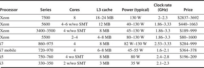
Figure 5.34 The characteristics for a range of Intel parts based on the Nehalem microarchitecture. This chart still collapses a variety of entries in each row (from 2 to 8!). The price is for an order of 1000 units.
In the 1980s and 1990s, with the birth and development of ILP, software in the form of optimizing compilers that could exploit ILP was key to its success. Similarly, the successful exploitation of thread-level parallelism will depend as much on the development of suitable software systems as it will on the contributions of computer architects. Given the slow progress on parallel software in the past 30-plus years, it is likely that exploiting thread-level parallelism broadly will remain challenging for years to come. Furthermore, your authors believe that there is significant opportunity for better multicore architectures. To design those architects will require a quantitative design discipline and the ability to accurately model tens to hundreds of cores running trillions of instructions, including large-scale applications and operating systems. Without such a methodology and capability, architects will be shooting in the dark. Sometimes you’re lucky, but often you miss.
5.11 Historical Perspectives and References
Section L.7 (available online) looks at the history of multiprocessors and parallel processing. Divided by both time period and architecture, the section features discussions on early experimental multiprocessors and some of the great debates in parallel processing. Recent advances are also covered. References for further reading are included.
Case Studies and Exercises by Amr Zaky and David A. Wood
Case Study 1: Single-Chip Multicore Multiprocessor
Concepts illustrated by this Case Study
The simple, multicore multiprocessor illustrated in Figure 5.35 represents a commonly implemented symmetric shared-memory architecture. Each processor has a single, private cache with coherence maintained using the snooping coherence protocol of Figure 5.7. Each cache is direct-mapped, with four blocks each holding two words. To simplify the illustration, the cache-address tag contains the full address, and each word shows only two hex characters, with the least significant word on the right. The coherence states are denoted M, S, and I (Modified, Shared, and Invalid).

where P# designates the CPU (e.g., P0), <op> is the CPU operation (e.g., read or write), <address> denotes the memory address, and <value> indicates the new word to be assigned on a write operation. Treat each action below as independently applied to the initial state as given in Figure 5.35. What is the resulting state (i.e., coherence state, tags, and data) of the caches and memory after the given action? Show only the blocks that change; for example, P0.B0: (I, 120, 00 01) indicates that CPU P0’s block B0 has the final state of I, tag of 120, and data words 00 and 01. Also, what value is returned by each read operation?

Consider two implementations with different performance characteristics summarized in Figure 5.36. Consider the following sequence of operations assuming the initial cache state in Figure 5.35. For simplicity, assume that the second operation begins after the first completes (even though they are on different processors):

For Implementation 1, the first read generates 50 stall cycles because the read is satisfied by P0’s cache. P1 stalls for 40 cycles while it waits for the block, and P0 stalls for 10 cycles while it writes the block back to memory in response to P1’s request. Thus, the second read by P3 generates 100 stall cycles because its miss is satisfied by memory, and this sequence generates a total of 150 stall cycles. For the following sequences of operations, how many stall cycles are generated by each implementation?


Unlocking a spin lock simply requires a store of the value 0:
![]()
As discussed in Section 5.5, the more optimized spin lock employs cache coherence and uses a load to check the lock, allowing it to spin with a shared variable in the cache:

Assume that processors P0, P1, and P3 are all trying to acquire a lock at address 0x100 (i.e., register R1 holds the value 0x100). Assume the cache contents from Figure 5.35 and the timing parameters from Implementation 1 in Figure 5.36. For simplicity, assume that the critical sections are 1000 cycles long.
where the write A results in a cache miss and the read B results in a cache hit. Under SC, the processor must stall read B until after it can order (and thus perform) write A. Simple implementations of SC will stall the processor until the cache receives the data and can perform the write. Weaker consistency models relax the ordering constraints on reads and writes, reducing the cases that the processor must stall. The Total Store Order (TSO) consistency model requires that all writes appear to occur in a total order but allows a processor’s reads to pass its own writes. This allows processors to implement write buffers that hold committed writes that have not yet been ordered with respect to other processors’ writes. Reads are allowed to pass (and potentially bypass) the write buffer in TSO (which they could not do under SC). Assume that one memory operation can be performed per cycle and that operations that hit in the cache or that can be satisfied by the write buffer introduce no stall cycles. Operations that miss incur the latencies listed in Figure 5.36. Assume the cache contents of Figure 5.35. How many stall cycles occur prior to each operation for both the SC and TSO consistency models?

Case Study 2: Simple Directory-Based Coherence
Concepts illustrated by this case study
Consider the distributed shared-memory system illustrated in Figure 5.37. It consists of two four-core chips. The processor in each chip share an L2 cache (L2$), and the two chips are connected via a point-to-point interconnect. The system memory is distributed across the two chips. Figure 5.38 zooms in on part of this system. Pi,j denotes processor i in chip j. Each processor has a single direct-mapped L1 cache that holds two blocks, each holding two words. Each chip has a single direct-mapped L2 cache that holds two blocks, each holding two words. To simplify the illustration, the cache address tags contain the full address and each word shows only two hex characters, with the least significant word on the right. The L1 cache states are denoted M, S, and I for Modified, Shared, and Invalid. Both the L2 caches and memories have directories. The directory states are denoted DM, DS, and DI for Directory Modified, Directory Shared, and Directory Invalid. The simple directory protocol is described in Figures 5.22 and 5.23. The L2 directory lists the local sharers/owners and additionally records if a line is shared externally in another chip; for example, P1,0;E denotes that a line is shared by local processor P1,0 and is externally shared in some other chip. The memory directory has a list of the chip sharers/owners of a line; for example, C0,C1 denotes that a line is shared in chips 0 and 1.


P#: <op> <address> [ <-- <value> ]
where P# designates the CPU (e.g., P0,0), <op> is the CPU operation (e.g., read or write), <address> denotes the memory address, and <value> indicates the new word to be assigned on a write operation. What is the final state (i.e., coherence state, sharers/owners, tags, and data) of the caches and memory after the given sequence of CPU operations has completed? Also, what value is returned by each read operation?

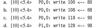
Case Study 3: Advanced Directory Protocol
Concepts illustrated by this case study
The directory coherence protocol in Case Study 2 describes directory coherence at an abstract level but assumes atomic transitions much like the simple snooping system. High-performance directory systems use pipelined, switched interconnects that greatly improve bandwidth but also introduce transient states and nonatomic transactions. Directory cache coherence protocols are more scalable than snooping cache coherence protocols for two reasons. First, snooping cache coherence protocols broadcast requests to all nodes, limiting their scalability. Directory protocols use a level of indirection—a message to the directory—to ensure that requests are only sent to the nodes that have copies of a block. Second, the address network of a snooping system must deliver requests in a total order, while directory protocols can relax this constraint. Some directory protocols assume no network ordering, which is beneficial since it allows adaptive routing techniques to improve network bandwidth. Other protocols rely on point-to-point order (i.e., messages from node P0 to node P1 will arrive in order). Even with this ordering constraint, directory protocols usually have more transient states than snooping protocols. Figure 5.39 presents the cache controller state transitions for a simplified directory protocol that relies on point-to-point network ordering. Figure 5.40 presents the directory controller’s state transitions.


For each block, the directory maintains a state and a current owner field or a current sharers’ list (if any). For the sake of the following discussion and ensuing problem, assume that the L2 caches are disabled. Assume that the memory directory lists sharers/owners at a processor granularity. For example, in Figure 5.38, the memory directory for line 108 would be “P0, 0; P3, 0” rather than “C0, C1”. Also, assume that messages cross chip boundaries—if needed—in a transparent way.
The row is indexed by the current state, and the column by the event determines the <action/nextstate> tuple. If only a next state is listed, then no action is required. Impossible cases are marked “error” and represent error conditions; “z” means the requested event cannot currently be processed.
The following example illustrates the basic operation of this protocol. Suppose a processor attempts a write to a block in state I (Invalid). The corresponding tuple is “send GetM/IMAD,” indicating that the cache controller should send a GetM (GetModified) request to the directory and transition to state IMAD. In the simplest case, the request message finds the directory in state DI (Directory Invalid), indicating that no other cache has a copy. The directory responds with a Data message that also contains the number of Acks to expect (in this case, zero). In this simplified protocol, the cache controller treats this single message as two messages: a Data message followed by a Last Ack event. The Data message is processed first, saving the data and transitioning to IMA. The Last Ack event is then processed, transitioning to state M. Finally, the write can be performed in state M.
If the GetM finds the directory in state DS (Directory Shared), the directory will send Invalidate (INV) messages to all nodes on the sharers’ list, send Data to the requester with the number of sharers, and transition to state M. When the INV messages arrive at the sharers, they will find the block in either state S or state I (if they have silently invalidated the block). In either case, the sharer will send an Ack directly to the requesting node. The requester will count the Acks it has received and compare that to the number sent back with the Data message. When all the Acks have arrived, the Last Ack event occurs, triggering the cache to transition to state M and allowing the write to proceed. Note that it is possible for all the Acks to arrive before the Data message, but not for the Last Ack event to occur. This is because the Data message contains the Ack count. Thus, the protocol assumes that the Data message is processed before the Last Ack event.


Consider an implementation with the performance characteristics summarized in Figure 5.41.

For the sequences of operations below, the cache contents of Figure 5.38, and the directory protocol above, what is the latency observed by each processor node?


Exercises
Assume that when i processors are in use, the applications run i times faster. Rewrite Amdahl’s law so it gives the speedup as a function of p for some application.

Assume that a processor supports a relaxed memory consistency model. A relaxed consistency model requires synchronization to be explicitly identified. Assume that the processor supports a “barrier” instruction, which ensures that all memory operations preceding the barrier instruction complete before any memory operations following the barrier are allowed to begin. Where would you include barrier instructions in the above code segment to ensure that you get the “intuitive results” of sequential consistency?