
Chapter 3. Network and Security Components, Concepts, and Architectures
This chapter covers the following topics:
![]() Advanced Network Design (Wired/Wireless): Concepts discussed include remote access, IPv6 and associated transitional technologies, transport encryption, network authentication methods, 802.1x, and mesh networks.
Advanced Network Design (Wired/Wireless): Concepts discussed include remote access, IPv6 and associated transitional technologies, transport encryption, network authentication methods, 802.1x, and mesh networks.
![]() Security Devices: Topics covered include unified threat management, network IPS and IDS systems, in-line network encryptors, security information and event management, hardware security modules, device placement, and application- and protocol-aware technologies.
Security Devices: Topics covered include unified threat management, network IPS and IDS systems, in-line network encryptors, security information and event management, hardware security modules, device placement, and application- and protocol-aware technologies.
![]() Networking Devices: Topics covered include switches, firewalls, wireless controllers, routers, and proxies.
Networking Devices: Topics covered include switches, firewalls, wireless controllers, routers, and proxies.
![]() Virtual Networking and Security Components: Topics covered include the virtualization of switches, firewalls, wireless controllers, routers, and proxies.
Virtual Networking and Security Components: Topics covered include the virtualization of switches, firewalls, wireless controllers, routers, and proxies.
![]() Complex Network Security Solutions for Data Flow: Topics covered include SSL inspection and network data flow.
Complex Network Security Solutions for Data Flow: Topics covered include SSL inspection and network data flow.
![]() Secure Configuration and Baselining of Networking and Security Components: Topics covered include access control lists, change monitoring, configuration lockdown, and availability controls.
Secure Configuration and Baselining of Networking and Security Components: Topics covered include access control lists, change monitoring, configuration lockdown, and availability controls.
![]() Software-Defined Networking: This section discusses an architecture that decouples the network control and forwarding functions.
Software-Defined Networking: This section discusses an architecture that decouples the network control and forwarding functions.
![]() Cloud-Managed Networks: This section discusses a technology that allows companies to easily configure, manage, and deploy networking devices such as those for wireless access.
Cloud-Managed Networks: This section discusses a technology that allows companies to easily configure, manage, and deploy networking devices such as those for wireless access.
![]() Network Management and Monitoring Tools: Topics covered include devices and software that can be used to identify and resolve network issues.
Network Management and Monitoring Tools: Topics covered include devices and software that can be used to identify and resolve network issues.
![]() Advanced Configuration of Routers, Switches, and Other Network Devices: Topics covered include transport security, trunking security, and route protection.
Advanced Configuration of Routers, Switches, and Other Network Devices: Topics covered include transport security, trunking security, and route protection.
![]() Security Zones: Topics covered include DMZs, data flow enforcement, and separation of critical assets.
Security Zones: Topics covered include DMZs, data flow enforcement, and separation of critical assets.
![]() Network Access Control: Topics covered include quarantine and remediation.
Network Access Control: Topics covered include quarantine and remediation.
![]() Operational and Consumer Network-Enabled Devices: This section discusses building automation systems, IP video, HVAC controllers, sensors, physical access control systems, AV systems, and scientific and industrial equipment.
Operational and Consumer Network-Enabled Devices: This section discusses building automation systems, IP video, HVAC controllers, sensors, physical access control systems, AV systems, and scientific and industrial equipment.
![]() Critical Infrastructure/Supervisory Control and Data Acquisition (SCADA)/Industrial Control Systems (ICS): This section discusses a system operating with coded signals over communication channels to provide control of remote equipment.
Critical Infrastructure/Supervisory Control and Data Acquisition (SCADA)/Industrial Control Systems (ICS): This section discusses a system operating with coded signals over communication channels to provide control of remote equipment.
This chapter covers CAS-002 objective 1.3.
A secure network design cannot be achieved without an understanding of the components that must be included and the concepts of secure design that must be followed. While it is true that many security features come at a cost of performance or ease of use, these are costs that most enterprises will be willing to incur if they understand some important security principles. This chapter discusses the building blocks of a secure architecture.
Foundation Topics
Advanced Network Design (Wired/Wireless)
Changes in network design and approaches to securing the network infrastructure come fast and furious. It is easy to fall behind and cling to outdated approaches. New technologies and new design principles are constantly coming. The following sections cover some the more recent advances and their costs and benefits.
Remote Access
The day when all workers gathered together in the same controlled environment to do their jobs is fast fading into the rearview mirror. Increasingly workers are working from other locations, such as their home or distant small offices. A secure remote access solution is critical as remote access becomes a more common method of connecting to corporate resources. The following sections discuss options for securing these connections.
VPNs
Virtual private network (VPN) connections use an untrusted carrier network but provide protection of the information through strong authentication protocols and encryption mechanisms. While we typically use the most untrusted network—the Internet—as the classic example, and most VPNs do travel through the Internet, a VPN can be used with interior networks as well whenever traffic needs to be protected from prying eyes.
In VPN operations, entire protocols wrap around other protocols when this process occurs. They include:
![]() A LAN protocol (required)
A LAN protocol (required)
![]() A remote access or line protocol (required)
A remote access or line protocol (required)
![]() An authentication protocol (optional)
An authentication protocol (optional)
![]() An encryption protocol (optional)
An encryption protocol (optional)
A device that terminates multiple VPN connections is called a VPN concentrator. VPN concentrators incorporate the most advanced encryption and authentication techniques available.
In some instances, VLANs in a VPN solution may not be supported by the ISP if they are also using VLANs in their internal network. Choosing a provider that provisions Multiprotocol Label Switching (MPLS) connections can allow customers to establish VLANs to other sites. MPLS provides VPN services with address and routing separation between VPNs.
VPN connections can be used to provide remote access to teleworkers or traveling users (called remote access VPNs) and can also be used to securely connect two locations (called site-to-site VPNs). The implementation process is conceptually different for these two. In the former, the tunnel that is created has as its endpoints the user’s computer and the VPN concentrator. In this case, only traffic traveling from the user computer to the VPN concentrator uses this tunnel.
In the case of two offices locations, the tunnel endpoints are the two VPN routers, one in each office. With this configuration, all traffic that goes between the offices will use the tunnel, regardless of the source or destination. The endpoints are defined during the creation of the VPN connection and thus must be set correctly according to the type of remote access link being used.
SSH
In many cases, administrators or network technicians need to manage and configure network devices remotely. Protocols such as Telnet allow these technicians to connect to devices such as routers, switches, and wireless access points to manage them from the command line. Telnet, however, transmits in cleartext, which is a security issue.
Secure Shell (SSH) was created to provide an encrypted method of performing these same procedures. It connects, via a secure channel over an insecure network, a server and a client running SSH server and SSH client programs, respectively. It is a widely used replacement for Telnet and should be considered when performing remote management from the command line.
Several steps can be taken to enhance the security of an SSH implementation. Among these steps are:
![]() Change the port number in use from the default of 22 to something above 1024.
Change the port number in use from the default of 22 to something above 1024.
![]() Use only version 2, which corrects many vulnerabilities that exist in earlier versions.
Use only version 2, which corrects many vulnerabilities that exist in earlier versions.
![]() Disable root login to devices that have a root account (in Linux or UNIX).
Disable root login to devices that have a root account (in Linux or UNIX).
![]() Control access to any SSH-enabled devices by using ACLs, IP tables, or TCP wrappers.
Control access to any SSH-enabled devices by using ACLs, IP tables, or TCP wrappers.
RDP
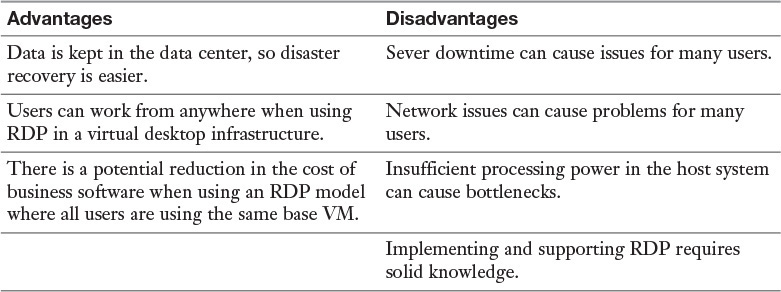
Remote Desktop Protocol (RDP) is a proprietary protocol developed by Microsoft that provides a graphical interface to connect to another computer over a network connection. Unlike Telnet and SSH, which allow only working from the command line, RDP enables you to work on a remote computer as if you were actually sitting at its console.
RDP sessions use native RDP encryption but do not authenticate the session host server. To mitigate this, you can use SSL for server authentication and to encrypt RDP session host server communications. This requires a certificate. You can use an existing certificate or the default self-signed certificate.
While RDP can be used for remote connections to a machine, it can also be used to connect users to a virtual desktop infrastructure (VDI). This allows the user to connect from anywhere and work from a virtual desktop. Each user may have his or her own virtual machine (VM) image, or many users may use images based on the same VM.
The advantages and disadvantages of RDP are described in Table 3-1.
VNC
Virtual Network Computing (VNC) operates much like RDP but uses the Remote Frame Buffer (RFB) protocol. Unlike RDP, VNC is platform independent. For example, it could be used to transmit between a Linux server and an OS X laptop. The VNC system contains the following components:
![]() The VNC server is the program on the machine that shares its screen.
The VNC server is the program on the machine that shares its screen.
![]() The VNC client (or viewer) is the program that watches, controls, and interacts with the server.
The VNC client (or viewer) is the program that watches, controls, and interacts with the server.
![]() The VNC protocol (RFB) is used to communicate between the VNC server and client.
The VNC protocol (RFB) is used to communicate between the VNC server and client.
Keep in mind when using VNC that any connections that go through a firewall will be on port 5900. It may be necessary to add a rule to the firewall to allow this traffic. Moreover, the VNC server should be safely placed in the internal network, and only local connections should be allowed to it. Any connections from outside the network should use a VPN or should use SSH through a more secure server. The VNC server should also be set to only allow viewing of sessions to minimize the damage if a breach occurs.
SSL
Secure Sockets Layer (SSL) is another option for creating secure connections to servers. It works at the application layer of the OSI model. It is used mainly to protect HTTP traffic or web servers. Its functionality is embedded in most browsers, and its use typically requires no action on the part of the user. It is widely used to secure Internet transactions. It can be implemented in two ways:
![]() SSL portal VPN: In this case, a user has a single SSL connection for accessing multiple services on the web server. Once authenticated, the user is provided a page that acts as a portal to other services.
SSL portal VPN: In this case, a user has a single SSL connection for accessing multiple services on the web server. Once authenticated, the user is provided a page that acts as a portal to other services.
![]() SSL tunnel VPN: A user may use an SSL tunnel to access services on a server that is not a web server. This solution uses custom programming to provide access to non-web services through a web browser.
SSL tunnel VPN: A user may use an SSL tunnel to access services on a server that is not a web server. This solution uses custom programming to provide access to non-web services through a web browser.
TLS and SSL are very similar but not the same. TLS 1.0 is based on the SSL 3.0 specification, but the two are not operationally compatible. Both implement confidentiality, authentication, and integrity above the transport layer. The server is always authenticated, and optionally the client can also be authenticated. SSL v2 must be used for client-side authentication. When configuring SSL, a session key length must be designated. The two options are 40-bit and 128-bit. Using self-signed certificates to authenticate the server’s public key prevents man-in-the-middle attacks.
SSL is often used to protect other protocols. Secure Copy Protocol (SCP), for example, uses SSL to secure file transfers between hosts. Some of the advantages and disadvantages of SSL are listed in Table 3-2.
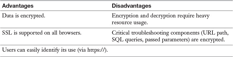
When placing the SSL gateway, you must consider a trade-off: The closer the gateway is to the edge of the network, the less encryption that needs to be performed in the LAN (and the less performance degradation), but the closer to the network edge it is placed, the farther the traffic travels through the LAN in the clear. The decision comes down to how much you trust your internal network.
IPv6 and Associated Transitional Technologies
IPv6 is an IP addressing scheme designed to provide a virtually unlimited number of IP addresses. It uses 128 bits rather than 32, as in IPv4, and it is represented in hexadecimal rather than dotted-decimal format. Moreover, any implementation of IPv6 requires support built in for Internet Protocol Security (IPsec), which is optional in IPv4. IPsec is used to protect the integrity and confidentiality of the data contained in a packet.
An IPv6 address looks different from an IPv4 address. When viewed in nonbinary format (it can be represented in binary and is processed by the computer in binary), it is organized into eight sections, or fields, instead of four, as in IPv4. The sections are separated by colons rather than periods, as in IPv4. Finally, each of the eight sections has four characters rather than one to three, as in the dotted-decimal format of IPv4. An IPv4 and IPv6 address are presented here for comparison:
IPv4: 192.168.5.6
IPv6: 2001:0db8:85a3:0000:0000:8a2e:0370:7334
The IPv6 address has two logical parts: a 64-bit network prefix and a 64-bit host address. The host address is automatically generated from the MAC address of the device. The host address in the example above consists of the rightmost four sections, or 0000:8a2e:0370:7334. The leftmost four sections are the network portion. This portion can be further subdivided. The first section to the left of the host portion can be used by organizations to identify a site within the organization. The other three far-left sections are assigned by the ISP or in some cases are generated automatically, based on the address type.
There are some allowed methods/rules of shortening the representation of the IPv6 address:
![]() Leading zeros in each section can be omitted, but each section must be represented by at least one character, unless you are making use of the next rule. By applying this rule, the previous IPv6 address example could be written as follows:
Leading zeros in each section can be omitted, but each section must be represented by at least one character, unless you are making use of the next rule. By applying this rule, the previous IPv6 address example could be written as follows:
2001:0db8:85a3:0:0:8a2e:0370:7334
![]() One or more consecutive sections with only a 0 can be represented with a single empty section (double colons), as shown here applied to the same address:
One or more consecutive sections with only a 0 can be represented with a single empty section (double colons), as shown here applied to the same address:
2001:0db8:85a3:: 8a2e:0370:7334
![]() The second rule can be applied only once within an address. For example, the following IPv6 address, which contains two sets of consecutive sections with all zeros, could have the second rule applied only once.
The second rule can be applied only once within an address. For example, the following IPv6 address, which contains two sets of consecutive sections with all zeros, could have the second rule applied only once.
2001:0000:0000:85a3:8a2e:0000:0000:7334
It could not be represented as follows:
2001::85a3:8a2e::7334
To alleviate some of the stress of changing over to IPv6, a number of transition mechanisms have been developed. Among them are:
![]() 6 to 4: This allows IPv6 sites to communicate with each other over an IPv4 network. IPv6 sites communicate with native IPv6 domains via relay routers. This effectively treats a wide area IPv4 network as a unicast point-to-point link layer.
6 to 4: This allows IPv6 sites to communicate with each other over an IPv4 network. IPv6 sites communicate with native IPv6 domains via relay routers. This effectively treats a wide area IPv4 network as a unicast point-to-point link layer.
![]() Teredo: This assigns addresses and creates host-to-host tunnels for unicast IPv6 traffic when IPv6 hosts are located behind IPv4 network address translators (NATs).
Teredo: This assigns addresses and creates host-to-host tunnels for unicast IPv6 traffic when IPv6 hosts are located behind IPv4 network address translators (NATs).
![]() Dual Stack: This solution runs both IPv4 and IPv6 on networking devices.
Dual Stack: This solution runs both IPv4 and IPv6 on networking devices.
![]() GRE tunnels: Generic Routing Encapsulation (GRE) can be used to carry IPv6 packets across an IPv4 network by encapsulating them in GRE IPv4 packets.
GRE tunnels: Generic Routing Encapsulation (GRE) can be used to carry IPv6 packets across an IPv4 network by encapsulating them in GRE IPv4 packets.
There are many more techniques, but these are some of the most common.
While there is a learning curve for those versed in IPv4, there are a number of advantages to using IPv6:
![]() Security: IPsec is built into the standard; it’s not an add-on.
Security: IPsec is built into the standard; it’s not an add-on.
![]() Larger address space: There are enough IPv6 addresses for every man, woman, and child on the face of the earth to each have the number of IP addresses that were available in IPv4.
Larger address space: There are enough IPv6 addresses for every man, woman, and child on the face of the earth to each have the number of IP addresses that were available in IPv4.
![]() Stateless autoconfiguration: It is possible for IPv6 devices to create their own IPv6 address, either link-local or global unicast.
Stateless autoconfiguration: It is possible for IPv6 devices to create their own IPv6 address, either link-local or global unicast.
![]() Better performance: Performance is better due to the simpler header.
Better performance: Performance is better due to the simpler header.
IPv6 does not remove all security issues, though. The following concerns still exist:
![]() Lack of training on IPv6: With so many devices already running IPv6, failure to secure it creates a backdoor.
Lack of training on IPv6: With so many devices already running IPv6, failure to secure it creates a backdoor.
![]() New threats: Current security products may lack the ability to recognize IPv6 threats.
New threats: Current security products may lack the ability to recognize IPv6 threats.
![]() Bugs in code of new IPv6 products: As products supporting IPv6 are rushed to market, in many cases, not all of the bugs have ben worked out.
Bugs in code of new IPv6 products: As products supporting IPv6 are rushed to market, in many cases, not all of the bugs have ben worked out.
Transport Encryption
Transport encryption includes any method that protects data in transit. We already discussed SSL/TLS earlier. The following sections discuss some additional methods.
FTP, FTPS, and SFTP
File Transfer Protocol (FTP) transfers files from one system to another. FTP is insecure in that the username and password are transmitted in cleartext. The original cleartext version uses TCP port 20 for data and TCP port 21 as the control channel. It is not recommended to use FTP when security is a consideration.
FTPS is FTP that adds support for the cryptographic protocols Transport Layer Security (TLS) and Secure Sockets Layer (SSL). FTPS uses TCP ports 989 and 990.
FTPS is not the same as and should not be confused with another secure version of FTP, SSH File Transfer Protocol (SFTP). Rather, it is an extension of the Secure Shell Protocol (SSH). There have been a number of different versions, with version 6 being the latest. Since it uses SSH for the file transfer, it uses TCP port 22.
HTTP, HTTPS, and SHTTP
One of the most frequently used protocols today is Hypertext Transfer Protocol (HTTP) and its secure versions, HTTPS and SHTTP. These protocols are discussed in Chapter 1, “Cryptographic Concepts and Techniques.” When implementing these protocols, you must configure any firewalls to allow the traffic to exit through the firewall. As this is usually done on the basis of port numbers, you need to know these port numbers. Table 3-3 lists the port numbers of these protocols.

Network Authentication Methods
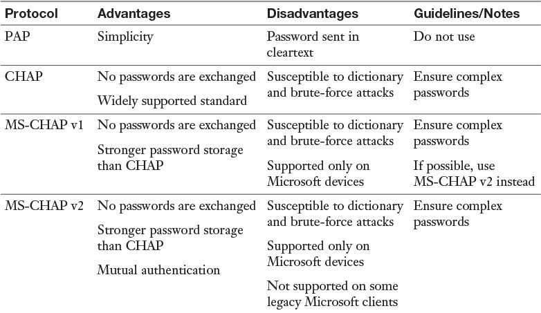
One of the protocol choices that must be made in creating a remote access solution is the authentication protocol. The following are some of the most important of those protocols:
![]() Password Authentication Protocol (PAP) provides authentication, but the credentials are sent in cleartext and can be read with a sniffer.
Password Authentication Protocol (PAP) provides authentication, but the credentials are sent in cleartext and can be read with a sniffer.
![]() Challenge Handshake Authentication Protocol (CHAP) solves the cleartext problem by operating without sending the credentials across the link. The server sends the client a set of random text called a challenge. The client encrypts the text with the password and sends it back. The server then decrypts it with the same password and compares the result with what was sent originally. If the results match, then the server can be assured that the user or system possesses the correct password without ever needing to send it across the untrusted network.
Challenge Handshake Authentication Protocol (CHAP) solves the cleartext problem by operating without sending the credentials across the link. The server sends the client a set of random text called a challenge. The client encrypts the text with the password and sends it back. The server then decrypts it with the same password and compares the result with what was sent originally. If the results match, then the server can be assured that the user or system possesses the correct password without ever needing to send it across the untrusted network.
![]() MS-CHAP v1: This is the first version of a variant of CHAP by Microsoft. This protocol works only with Microsoft devices, and while it stores the password more securely than CHAP, like any other password-based system, it is susceptible, to brute-force and dictionary attacks.
MS-CHAP v1: This is the first version of a variant of CHAP by Microsoft. This protocol works only with Microsoft devices, and while it stores the password more securely than CHAP, like any other password-based system, it is susceptible, to brute-force and dictionary attacks.
![]() MS-CHAP v2: This is an update to MS-CHAP. It provided stronger encryption keys and mutual authentication, and it uses different keys for sending and receiving.
MS-CHAP v2: This is an update to MS-CHAP. It provided stronger encryption keys and mutual authentication, and it uses different keys for sending and receiving.
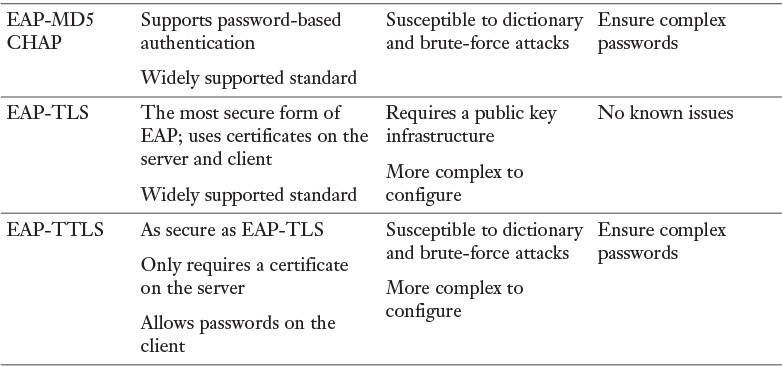
![]() Extensible Authentication Protocol (EAP) is not a single protocol but a framework for port-based access control that uses the same three components that are used in RADIUS. A wide variety of these implementations can use all sorts of authentication mechanisms, including certificates, a PKI, or even simple passwords.
Extensible Authentication Protocol (EAP) is not a single protocol but a framework for port-based access control that uses the same three components that are used in RADIUS. A wide variety of these implementations can use all sorts of authentication mechanisms, including certificates, a PKI, or even simple passwords.
![]() EAP-MD5-CHAP: This variant of EAP uses the CHAP challenge process, but the challenges and responses are sent as EAP messages. It allows the use of passwords with EAP.
EAP-MD5-CHAP: This variant of EAP uses the CHAP challenge process, but the challenges and responses are sent as EAP messages. It allows the use of passwords with EAP.
![]() EAP-TLS: This form of EAP requires a public key infrastructure because it requires certificates on both server and clients. It is, however, immune to password-based attacks as it does not use passwords.
EAP-TLS: This form of EAP requires a public key infrastructure because it requires certificates on both server and clients. It is, however, immune to password-based attacks as it does not use passwords.
![]() EAP-TTLS: This form of EAP requires a certificate on the server only. The client uses a password, but the password is sent within a protected EAP message. It is, however, susceptible to password-based attacks.
EAP-TTLS: This form of EAP requires a certificate on the server only. The client uses a password, but the password is sent within a protected EAP message. It is, however, susceptible to password-based attacks.
Table 3-4 compares the authentication protocols described here.
Authentication Factors
Once the user identification method has been established, an organization must decide which authentication method to use. Authentication methods are divided into five broad categories:
![]() Knowledge factor authentication: Something a person knows
Knowledge factor authentication: Something a person knows
![]() Ownership factor authentication: Something a person has
Ownership factor authentication: Something a person has
![]() Characteristic factor authentication: Something a person is
Characteristic factor authentication: Something a person is
![]() Location factor authentication: Somewhere a person is
Location factor authentication: Somewhere a person is
![]() Action factor authentication: Something a person does
Action factor authentication: Something a person does
Authentication usually ensures that a user provides at least one factor from these categories, which is referred to as single-factor authentication. An example of this would be providing a username and password at login. Two-factor authentication ensures that the user provides two of the three factors. An example of two-factor authentication would be providing a username, password, and smart card at login. Three-factor authentication ensures that a user provides three factors. An example of three-factor authentication would be providing a username, password, smart card, and fingerprint at login. For authentication to be considered strong authentication, a user must provide factors from at least two different categories. (Note that the username is the identification factor, not an authentication factor.)
You should understand that providing multiple authentication factors from the same category is still considered single-factor authentication. For example, if a user provides a username, password, and the user’s mother’s maiden name, single-factor authentication is being used. In this example, the user is still only providing factors that are something a person knows.
Knowledge Factors
As briefly described above, knowledge factor authentication is authentication that is provided based on something a person knows. This type of authentication is referred to as a Type I authentication factor. While the most popular form of authentication used by this category is password authentication, other knowledge factors can be used, including date of birth, mother’s maiden name, key combination, or PIN.
As briefly described above, ownership factor authentication is authentication that is provided based on something that a person has. This type of authentication is referred to as a Type II authentication factor. Ownership factors can include the following:
![]() Token devices: A token device is a handheld device that presents the authentication server with the one-time password. If the authentication method requires a token device, the user must be in physical possession of the device to authenticate. So although the token device provides a password to the authentication server, the token device is considered a Type II authentication factor because its use requires ownership of the device. A token device is usually implemented only in very secure environments because of the cost of deploying the token device. In addition, token-based solutions can experience problems because of the battery lifespan of the token device.
Token devices: A token device is a handheld device that presents the authentication server with the one-time password. If the authentication method requires a token device, the user must be in physical possession of the device to authenticate. So although the token device provides a password to the authentication server, the token device is considered a Type II authentication factor because its use requires ownership of the device. A token device is usually implemented only in very secure environments because of the cost of deploying the token device. In addition, token-based solutions can experience problems because of the battery lifespan of the token device.
![]() Memory cards: A memory card is a swipe card that is issued to a valid user. The card contains user authentication information. When the card is swiped through a card reader, the information stored on the card is compared to the information that the user enters. If the information matches, the authentication server approves the login. If it does not match, authentication is denied. Because the card must be read by a card reader, each computer or access device must have its own card reader. In addition, the cards must be created and programmed. Both of these steps add complexity and cost to the authentication process. However, it is often worth the extra complexity and cost for the added security it provides, which is a definite benefit of this system. However, the data on the memory cards is not protected, and this is a weakness that organizations should consider before implementing this type of system. Memory-only cards are very easy to counterfeit.
Memory cards: A memory card is a swipe card that is issued to a valid user. The card contains user authentication information. When the card is swiped through a card reader, the information stored on the card is compared to the information that the user enters. If the information matches, the authentication server approves the login. If it does not match, authentication is denied. Because the card must be read by a card reader, each computer or access device must have its own card reader. In addition, the cards must be created and programmed. Both of these steps add complexity and cost to the authentication process. However, it is often worth the extra complexity and cost for the added security it provides, which is a definite benefit of this system. However, the data on the memory cards is not protected, and this is a weakness that organizations should consider before implementing this type of system. Memory-only cards are very easy to counterfeit.
![]() Smart cards: A smart card accepts, stores, and sends data but can hold more data than a memory card. Smart cards, often known as integrated circuit cards (ICCs), contain memory like a memory card but also contain an embedded chip like bank or credit cards. Smart cards use card readers. However, the data on the smart card is used by the authentication server without user input. To protect against lost or stolen smart cards, most implementations require the user to input a secret PIN, meaning the user is actually providing both Type I (PIN) and Type II (smart card) authentication factors.
Smart cards: A smart card accepts, stores, and sends data but can hold more data than a memory card. Smart cards, often known as integrated circuit cards (ICCs), contain memory like a memory card but also contain an embedded chip like bank or credit cards. Smart cards use card readers. However, the data on the smart card is used by the authentication server without user input. To protect against lost or stolen smart cards, most implementations require the user to input a secret PIN, meaning the user is actually providing both Type I (PIN) and Type II (smart card) authentication factors.
Characteristic Factors
As briefly described above, characteristic factor authentication is authentication that is provided based on something a person is. This type of authentication is referred to as a Type III authentication factor. Biometric technology is the technology that allows users to be authenticated based on physiological or behavioral characteristics. Physiological characteristics include any unique physical attribute of the user, including iris, retina, and fingerprints. Behavioral characteristics measure a person’s actions in a situation, including voice patterns and data entry characteristics.
Additional Authentication Concepts
The following are some additional authentication concepts with which all security professionals should be familiar:
![]() Time-based One-time Password Algorithm (TOTP): This is an algorithm that computes a password from a shared secret and the current time. It is based on HOTP but turns the current time into an integer-based counter.
Time-based One-time Password Algorithm (TOTP): This is an algorithm that computes a password from a shared secret and the current time. It is based on HOTP but turns the current time into an integer-based counter.
![]() HMAC-based One-time Password Algorithm (HOTP): This is an algorithm that computes a password from a shared secret that is used one time only. It uses an incrementing counter that is synchronized on both the client and the server to do this.
HMAC-based One-time Password Algorithm (HOTP): This is an algorithm that computes a password from a shared secret that is used one time only. It uses an incrementing counter that is synchronized on both the client and the server to do this.
![]() Single sign-on: This is provided when an authentication system requires a user to only authenticate once to access all network resources.
Single sign-on: This is provided when an authentication system requires a user to only authenticate once to access all network resources.
802.1x
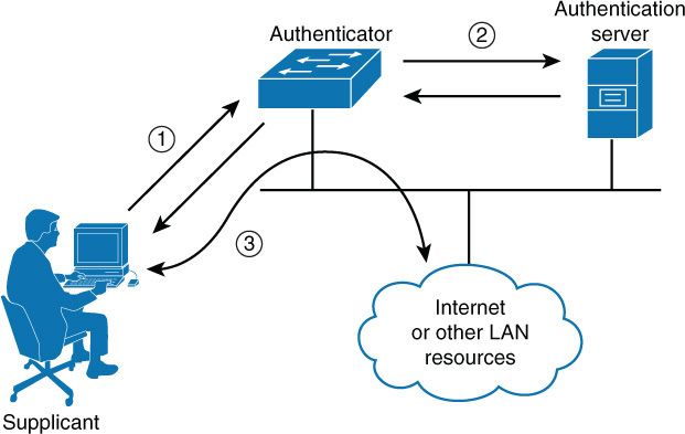
802.1x is a standard that defines a framework for centralized port-based authentication. It can be applied to both wireless and wired networks and uses three components:
![]() Supplicant: The user or device requesting access to the network
Supplicant: The user or device requesting access to the network
![]() Authenticator: The device through which the supplicant is attempting to access the network
Authenticator: The device through which the supplicant is attempting to access the network
![]() Authentication server: The centralized device that performs authentication
Authentication server: The centralized device that performs authentication
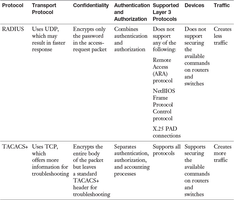
The role of the authenticator can be performed by a wide variety of network access devices, including remote access servers (both dial-up and VPN), switches, and wireless access points. The role of the authentication server can be performed by a Remote Authentication Dial-in User Service (RADIUS) or Terminal Access Controller Access Control System + (TACACS+) server. The authenticator requests credentials from the supplicant and, upon receipt of those credentials, relays them to the authentication server, where they are validated. Upon successful verification, the authenticator is notified to open the port for the supplicant to allow network access. This process is illustrated in Figure 3-1.
While RADIUS and TACACS+ perform the same roles, they have different characteristics. These differences must be taken into consideration when choosing a method. Keep in mind also that while RADUIS is a standard, TACACS+ is Cisco proprietary. Table 3-5 compares them.
Many consider enabling 802.1x authentication on all devices to be the best protection you can provide a network.
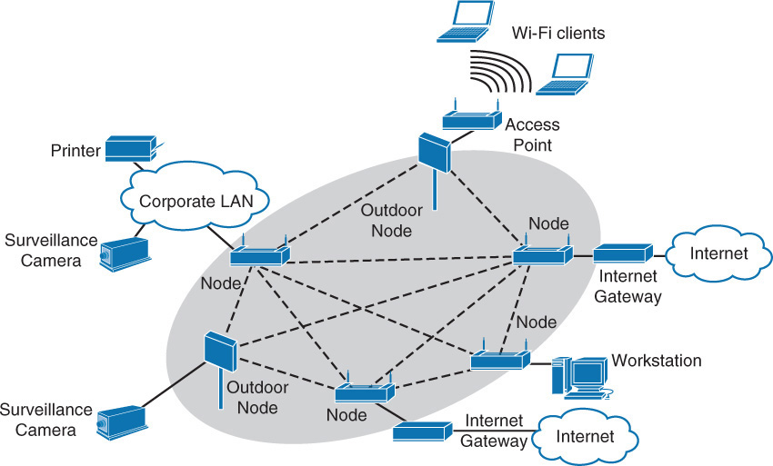
Mesh Networks
A mesh network is a network in which all nodes cooperate to relay data and are all connected to one another. To ensure complete availability, continuous connections are provided by using self-healing algorithms that are used to route around broken or blocked paths.
One area where this concept has been utilized is in wireless mesh networking. When one node can no longer operate, the rest of the nodes can still communicate with each other, directly or through one or more intermediate nodes. This is accomplished with one of several protocols, including:
![]() Ad Hoc Configuration Protocol (AHCP)
Ad Hoc Configuration Protocol (AHCP)
![]() Proactive Autoconfiguration (PAA)
Proactive Autoconfiguration (PAA)
![]() Dynamic WMN Configuration Protocol (DWCP)
Dynamic WMN Configuration Protocol (DWCP)
In Figure 3-2, multiple connections between the wireless nodes allow one of these protocols to self-heal the network by routing around broken links in real time.
Application of Solutions
This chapter has already covered a number of network design approaches and solutions. Although knowledge of these solutions is certainly valuable, the proper application of these solutions to a given scenario is the true test of your understanding. Consider a scenario with the following network:
![]() 37 workstations
37 workstations
![]() 3 printers
3 printers
![]() 48 port switch
48 port switch
![]() The latest patches and up-to-date antivirus software
The latest patches and up-to-date antivirus software
![]() An enterprise class router
An enterprise class router
![]() A firewall at the boundary to the ISP
A firewall at the boundary to the ISP
![]() Two-factor authentication
Two-factor authentication
![]() Encrypted sensitive data on each workstation
Encrypted sensitive data on each workstation
This scenario seems secure, but can you tell what’s missing? That’s right: There’s no transport security. Data traveling around the network is unencrypted!
Now consider another scenario. This time, two companies are merging, and their respective authentication systems are:
Company A: Captive portal using LDAP
Company B: 802.1x with a RADIUS server
What would be the best way to integrate these networks: Use the captive portal or switch Company A to 802.1x? If you said 802.1x, you are correct. It is a superior method to using a captive portal, which uses passwords that can be spoofed; 802.1x uses certificates for devices.
Now consider one more scenario. You are a consultant and have been asked to suggest an improvement in the following solution:
![]() End-to-end encryption via SSL in the DMZ
End-to-end encryption via SSL in the DMZ
![]() IPsec in transport mode with Authentication Headers (AH) enabled and Encrypted Security Payload (ESP) disabled throughout the internal network
IPsec in transport mode with Authentication Headers (AH) enabled and Encrypted Security Payload (ESP) disabled throughout the internal network
You need to minimize the performance degradation of the improvement.
What would you do? If you said enable ESP in the network, you are wrong. That would cause all traffic to be encrypted, which would increase security but would degrade performance. A better suggestion would be to change from SSL in the DMZ to TLS. TLS versions 1.1 and 1.2 are significantly more secure and fix many vulnerabilities present in SSL v3.0 and TLS v1.0.
Security Devices
To implement a secure network, you need to understand the available security devices and their respective capabilities. The following sections discuss a variety of devices, both hardware and software based.
UTM
Unified threat management (UTM) is an approach that involves performing multiple security functions within the same device or appliance. The functions may include:
![]() Network firewalling
Network firewalling
![]() Network intrusion prevention
Network intrusion prevention
![]() Gateway antivirus
Gateway antivirus
![]() Gateway antispam
Gateway antispam
![]() Content filtering
Content filtering
![]() Load balancing
Load balancing
![]() Data leak prevention
Data leak prevention
![]() On-appliance reporting
On-appliance reporting
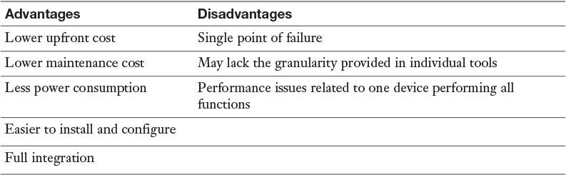
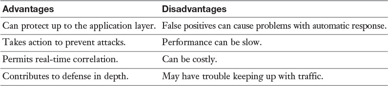
UTM makes administering multiple systems unnecessary. However, some feel that UTM creates a single point of failure and favor creating multiple layers of devices as a more secure approach. Some additional advantages and disadvantages of UTM are listed in Table 3-6.
NIPS
A network intrusion prevention system (NIPS) scans traffic on a network for signs of malicious activity and then takes some action to prevent it. A NIPS monitors the entire network. You need to be careful to set a NIPS’s filter in such a way that the generation of false positives and false negatives are kept to a minimum. False positives indicate an unwarranted alarm, and false negatives indicate troubling traffic that does not generate an alarm. The advantages and disadvantages of NIPS devices are shown in Table 3-7.
NIDS
An intrusion detection system (IDS) is a system responsible for detecting unauthorized access or attacks. It can verify, itemize, and characterize threats from outside and inside the network. Most IDSs are programmed to react certain ways in specific situations. Event notification and alerts are crucial to IDSs. These notifications and alerts inform administrators and security professionals when and where attacks are detected. The most common way to classify an IDS is based on its information source: network based or host based.
The most common IDS, a network-based IDS (NIDS), monitors network traffic on a local network segment. To monitor traffic on the network segment, the network interface card (NIC) must be operating in promiscuous mode. An NIDS can only monitor the network traffic. It cannot monitor any internal activity that occurs within a system, such as an attack against a system that is carried out by logging on to the system’s local terminal. An NIDS is affected by a switched network because generally an NIDS monitors only a single network segment.
IDS implementations are further divided into the following categories:
![]() Signature-based IDS: This type of IDS analyzes traffic and compares it to attack or state patterns, called signatures, that reside within the IDS database. It is also referred to as a misuse-detection system. While this type of IDS is very popular, it can only recognize attacks as compared with its database and is therefore only as effective as the signatures provided. Frequent updates are necessary. There are two main types of signature-based IDSs:
Signature-based IDS: This type of IDS analyzes traffic and compares it to attack or state patterns, called signatures, that reside within the IDS database. It is also referred to as a misuse-detection system. While this type of IDS is very popular, it can only recognize attacks as compared with its database and is therefore only as effective as the signatures provided. Frequent updates are necessary. There are two main types of signature-based IDSs:
![]() Pattern-matching: This type of IDS compares traffic to a database of attack patterns. The IDS carries out specific steps when it detects traffic that matches an attack pattern.
Pattern-matching: This type of IDS compares traffic to a database of attack patterns. The IDS carries out specific steps when it detects traffic that matches an attack pattern.
![]() Stateful-matching: This type of IDS records the initial operating system state. Any changes to the system state that specifically violate the defined rules result in an alert or a notification being sent.
Stateful-matching: This type of IDS records the initial operating system state. Any changes to the system state that specifically violate the defined rules result in an alert or a notification being sent.
![]() Anomaly-based IDS: This type of IDS analyzes traffic and compares it to normal traffic to determine whether that traffic is a threat. It is also referred to as a behavior-based, or profile-based, system. The problem with this type of system is that any traffic outside expected norms is reported, resulting in more false positives than with signature-based systems. There are five main types of anomaly-based IDSs:
Anomaly-based IDS: This type of IDS analyzes traffic and compares it to normal traffic to determine whether that traffic is a threat. It is also referred to as a behavior-based, or profile-based, system. The problem with this type of system is that any traffic outside expected norms is reported, resulting in more false positives than with signature-based systems. There are five main types of anomaly-based IDSs:
![]() Statistical anomaly-based IDS: This type of IDS samples the live environment to record activities. The longer the IDS is in operation, the more accurate the profile that is built. However, developing a profile that will not have a large number of false positives can be difficult and time-consuming. Thresholds for activity deviations are important in this type of IDS. Too low a threshold will result in false positives, while too high a threshold will result in false negatives.
Statistical anomaly-based IDS: This type of IDS samples the live environment to record activities. The longer the IDS is in operation, the more accurate the profile that is built. However, developing a profile that will not have a large number of false positives can be difficult and time-consuming. Thresholds for activity deviations are important in this type of IDS. Too low a threshold will result in false positives, while too high a threshold will result in false negatives.
![]() Protocol anomaly-based IDS: This type of IDS has knowledge of the protocols that it will monitor. A profile of normal usage is built and compared to activity.
Protocol anomaly-based IDS: This type of IDS has knowledge of the protocols that it will monitor. A profile of normal usage is built and compared to activity.
![]() Traffic anomaly-based IDS: This type of IDS tracks traffic pattern changes. All future traffic patterns are compared to the sample. Changing the threshold reduces the number of false positives or false negatives. This type of filter is excellent for detecting unknown attacks. But user activity may not be static enough to effectively implement such a system.
Traffic anomaly-based IDS: This type of IDS tracks traffic pattern changes. All future traffic patterns are compared to the sample. Changing the threshold reduces the number of false positives or false negatives. This type of filter is excellent for detecting unknown attacks. But user activity may not be static enough to effectively implement such a system.
![]() Rule- or heuristic-based IDS: This type of IDS is an expert system that uses a knowledge base, an inference engine, and rule-based programming. The knowledge is configured as rules. The data and traffic are analyzed, and the rules are applied to the analyzed traffic. The inference engine uses its intelligent software to “learn.” If characteristics of an attack are met, alerts or notifications are triggered. This is often referred to as an if/then, or expert, system.
Rule- or heuristic-based IDS: This type of IDS is an expert system that uses a knowledge base, an inference engine, and rule-based programming. The knowledge is configured as rules. The data and traffic are analyzed, and the rules are applied to the analyzed traffic. The inference engine uses its intelligent software to “learn.” If characteristics of an attack are met, alerts or notifications are triggered. This is often referred to as an if/then, or expert, system.
![]() Application-based IDS: This is a specialized IDS that analyzes transaction log files for a single application. This type of IDS is usually provided as part of the application or can be purchased as an add-on.
Application-based IDS: This is a specialized IDS that analyzes transaction log files for a single application. This type of IDS is usually provided as part of the application or can be purchased as an add-on.
![]() While an IDS should be a part of any network security solution, there are some limitations to this technology, including the following:
While an IDS should be a part of any network security solution, there are some limitations to this technology, including the following:
![]() Network noise limits effectiveness by creating false positives.
Network noise limits effectiveness by creating false positives.
![]() A high number of false positives can cause a lax attitude on the part of the security team.
A high number of false positives can cause a lax attitude on the part of the security team.
![]() Signatures must be updated constantly.
Signatures must be updated constantly.
![]() There is lag time between the release of an attack and the release of the corresponding signature.
There is lag time between the release of an attack and the release of the corresponding signature.
![]() An IDS cannot address authentication issues.
An IDS cannot address authentication issues.
![]() Encrypted packets cannot be analyzed.
Encrypted packets cannot be analyzed.
![]() In some cases, IDS software is susceptible to attacks.
In some cases, IDS software is susceptible to attacks.
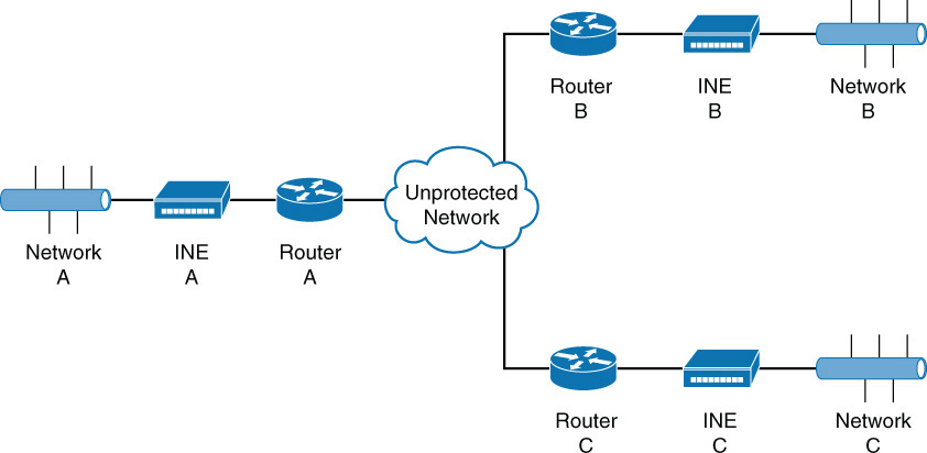
INE
An in-line network encryptor (INE), also called a high-assurance Internet Protocol encryptor (HAIPE), is a Type I encryption device. Type I designation indicates that it is a system certified by the NSA for use in securing U.S. government classified documents. To achieve this designation, the system must use NSA-approved algorithms. Such systems are seen in governmental, particularly DoD, deployments.
INE devices may also support routing and layer 2 VLANs. They also are built to be easily disabled and cleared of keys if in danger of physical compromise, using a technique called zeroization. INE devices are placed in each network that needs their services, and the INE devices communicate with one another through a secure tunnel.
SIEM
Security information and event management (SIEM) utilities receive information from log files of critical systems and centralize the collection and analysis of this data. SIEM technology is an intersection of two closely related technologies: security information management (SIM) and security event management (SEM). Figure 3-3 displays the relationship between the reporting, event management, and log analysis components.
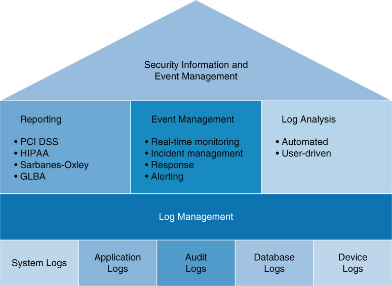
Log sources for SIEM can include the following:
![]() Application logs
Application logs
![]() Antivirus logs
Antivirus logs
![]() Operating system logs
Operating system logs
![]() Malware detection logs
Malware detection logs
One consideration when working with an SIEM system is to limit the amount of information collected to just what is really needed. Moreover, you need to ensure that adequate resources are available to ensure good performance.
In summary, an organization should implement an SIEM system when:
![]() More visibility into network events is desired
More visibility into network events is desired
![]() Faster correlation of events is required
Faster correlation of events is required
![]() Compliance issues require reporting to be streamlined and automated
Compliance issues require reporting to be streamlined and automated
![]() They need help prioritizing security issues
They need help prioritizing security issues
HSM
A hardware security module (HSM) is an appliance that safeguards and manages digital keys used with strong authentication and provides crypto processing. It attaches directly to a computer or server. Among the functions of an HSM are:
![]() Onboard secure cryptographic key generation
Onboard secure cryptographic key generation
![]() Onboard secure cryptographic key storage and management
Onboard secure cryptographic key storage and management
![]() Use of cryptographic and sensitive data material
Use of cryptographic and sensitive data material
![]() Offloading application servers for complete asymmetric and symmetric cryptography
Offloading application servers for complete asymmetric and symmetric cryptography
Not all HSM devices support the same functions. Each HSM has different features and different encryption technologies. Some of them might not support a strong enough encryption level for an enterprise’s needs. An additional consideration is that because these are physical devices and are portable, physical security must be ensured for any devices to which an HSM device is attached.
HSM devices can be used in a variety of scenarios, including:
![]() In a PKI environment to generate, store, and manage key pairs.
In a PKI environment to generate, store, and manage key pairs.
![]() In card payment systems to encrypt PINs and to load keys into protected memory.
In card payment systems to encrypt PINs and to load keys into protected memory.
![]() To perform the processing for applications that use SSL.
To perform the processing for applications that use SSL.
![]() In Domain Name System Security Extensions (DNSSEC) to store the keys used to signing zone file. This is a secure form of DNS that protects the integrity of zone files.
In Domain Name System Security Extensions (DNSSEC) to store the keys used to signing zone file. This is a secure form of DNS that protects the integrity of zone files.
There are some drawbacks to an HSM, including the following:
![]() High cost
High cost
![]() Lack of a standard for the strength of the random number generator
Lack of a standard for the strength of the random number generator
![]() Difficulty in upgrading
Difficulty in upgrading
When an HSM product is selected, you must ensure that it provides the services needed, based on its application. Remember that each HSM has different features and different encryption technologies, and some of them might not support a strong enough encryption level for an enterprise’s needs. Moreover, you should keep in mind the portable nature of these devices and protect the physical security of the area where they are connected.
Placement of Devices
The placement of a security device is driven by the functions it provides and the systems it is supposed to protect. Let’s talk about where to place the devices we have discussed so far in this chapter.
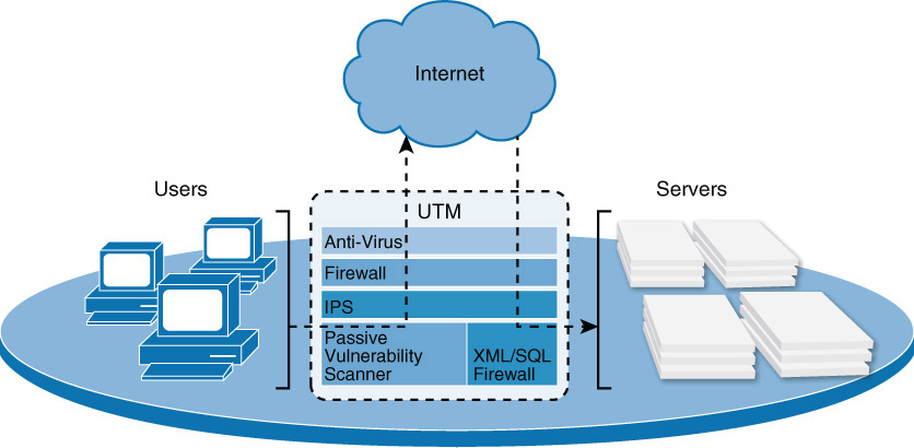
UTM
A UTM device should be placed between the LAN and the connection to the Internet, as shown in Figure 3-4.
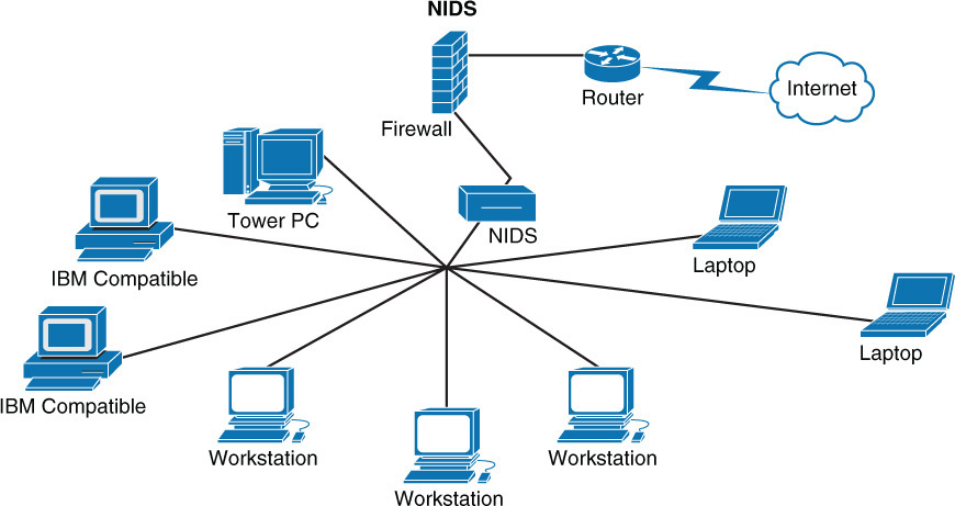
NIDS
Where you place a NIDS depends on the needs of the organization. To identify malicious traffic coming in from the Internet only, you should place it outside the firewall. On the other hand, placing the NIDS inside the firewall will enable the system to identify internal attacks and attacks that get through the firewall. In cases where multiple sensors can be deployed, you might place NIDS devices in both locations. When the budget allows, you should place any additional sensors closer to the sensitive systems in the network. When only a single sensor can be placed, all traffic should be funneled through it, regardless of whether it is inside or outside the firewall (see Figure 3-5).
INE
You place an INE or an HAIPE device in a network whose data is to be secured, at the point where the network has a connection to an unprotected network.
In Figure 3-6, any traffic that comes from Network A destined for either Network B or C goes through HAIPE A, is encrypted, encapsulated with headers that are appropriate for the transit network, and then sent out onto the insecure network. The receiving HAIPE device then decrypts the data packet and sends it on to the destination network.
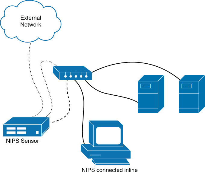
NIPS
You should place an NIPS at the border of the network and connect it in-line between the external network and the internal network, as shown in Figure 3-7.
SIEM
You should place an SIEM device in a central location where all reporting systems can reach it. Moreover, given the security information it contains, you should put it in a secured portion of the network. More important than the placement, though, is the tuning of the system so that it doesn’t gather so much information that it is unusable.
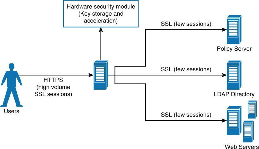
HSM
Figure 3-8 shows a typical placement of an HSM. These devices also exist in network card form.
Application- and Protocol-Aware Technologies
Application- and protocol-aware technologies maintain current information about applications and the protocols used to connect to them. These intelligent technologies use this information to optimize the functioning of the protocol and thus the application. The following sections look at some of these technologies.
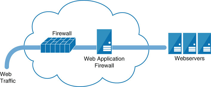
WAF
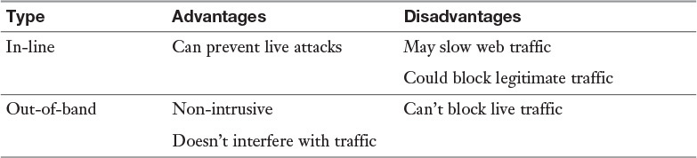
A web application firewall (WAF) applies rule sets to an HTTP conversation. These rule sets cover common attack types to which these session types are susceptible. Among the common attacks they address are cross-site scripting and SQL injections. A WAF can be implemented as an appliance or as a server plug-in. In appliance form, a WAF is typically placed directly behind the firewall and in front of the web server farm; Figure 3-9 shows an example. While all traffic is usually funneled in-line through the device, some solutions, however, monitor a port and operate out-of-band. Table 3-8 lists the pros and cons of these two approaches. Finally, WAFs can be installed directly on the web servers themselves.
The security issues involved with WAFs include the following:
![]() The IT infrastructure becomes more complex.
The IT infrastructure becomes more complex.
![]() Training on the WAF must be provided with each new release of the web application.
Training on the WAF must be provided with each new release of the web application.
![]() Testing procedures may change with each release.
Testing procedures may change with each release.
![]() False positives may occur and have a significant business impact.
False positives may occur and have a significant business impact.
![]() Troubleshooting becomes more complex.
Troubleshooting becomes more complex.
![]() The WAF terminating the application session can potentially have an effect on the web application.
The WAF terminating the application session can potentially have an effect on the web application.
NextGen Firewalls
Next-generation firewalls (NGFWs) are a category of devices that attempt to address traffic inspection and application awareness shortcomings of a traditional stateful firewall, without hampering the performance. Although UTM devices also attempt to address these issues, they tend to use separate internal engines to perform individual security functions. This means a packet may be examined several times by different engines to determine whether it should be allowed into the network.
NGFWs are application aware, which means they can distinguish between specific applications instead of allowing all traffic coming in via typical web ports. Moreover, they examine packets only once during the deep packet inspection phase (which is required to detect malware and anomalies). Among the features provided NGFWs are:
![]() Non-disruptive in-line configuration (which has little impact on network performance)
Non-disruptive in-line configuration (which has little impact on network performance)
![]() Standard first-generation firewall capabilities, such as network address translation (NAT), stateful protocol inspection (SPI), and virtual private networking (VPN)
Standard first-generation firewall capabilities, such as network address translation (NAT), stateful protocol inspection (SPI), and virtual private networking (VPN)
![]() Integrated signature-based IPS engine
Integrated signature-based IPS engine
![]() Application awareness, full stack visibility, and granular control
Application awareness, full stack visibility, and granular control
![]() Ability to incorporate information from outside the firewall, such as directory-based policy, blacklists, and whitelists
Ability to incorporate information from outside the firewall, such as directory-based policy, blacklists, and whitelists
![]() Upgrade path to include future information feeds and security threats and SSL decryption to enable identifying undesirable encrypted applications
Upgrade path to include future information feeds and security threats and SSL decryption to enable identifying undesirable encrypted applications
A NGFW can be paced in-line or out-of-path. Out-of-path means that a gateway redirects traffic to the NGFW, while in-line placement causes all traffic to flow through the device. The two placements are shown in Figure 3-10.
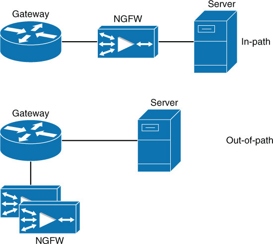
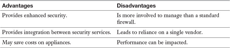
The advantages and disadvantages of NGFWs are listed in Table 3-9.
IPS
An intrusion protection system (IPS) is a system responsible for preventing attacks. These devices are discussed earlier in this chapter, in the section “NIPS.”
Passive Vulnerability Scanners
Vulnerability scanners are tools or utilities used to probe and reveal weaknesses in a network’s security. A passive vulnerability scanner (PVS) monitors network traffic at the packet layer to determine topology, services, and vulnerabilities. It avoids the instability that can be introduced to a system by actively scanning for vulnerabilities.
PVS tools analyze the packet stream and look for vulnerabilities through direct analysis. They are deployed much like a network IDS or packet analyzer. A PVS can pick a network session that targets a protected server and monitor it as much as needed. The biggest benefit of a PVS is its ability to do this without impacting the monitored network.
Active Vulnerability Scanners
Whereas passive scanners can only gather information, active scanners can take action to block an attack, such as block a dangerous IP address. They can also be used to simulate an attack to assess readiness. They operate by sending transmissions to nodes and examining the responses. Because of this, these scanners may disrupt network traffic.
Regardless of whether it’s active or passive, a vulnerability scanner cannot replace the expertise of trained security personnel. Moreover, these scanners are only as effective as the signature databases on which they depend, so the databases must be updated regularly. Finally, scanners require bandwidth and potentially slow the network.
For best performance, you can place a vulnerability scanner in a subnet that needs to be protected. You can also connect a scanner through a firewall to multiple subnets; this complicates the configuration and requires opening ports on the firewall, which could be problematic and could impact the performance of the firewall.
DAM
Database activity monitors (DAMs) monitor transactions and the activity of database services. They can be used for monitoring unauthorized access and fraudulent activities as well as for compliance auditing. Several implementations exist, with each operating and gathering information at different levels. A DAM typically performs continuously and in real time. In many cases, these systems operate independently of the database management system and do not rely on the logs created by these systems. Among the architectures used are:
![]() Interception-based model: Watches the communications between the client and the server.
Interception-based model: Watches the communications between the client and the server.
![]() Memory-based model: Uses a sensor attached to the database and continually polls the system to collect the SQL statements as they are being performed.
Memory-based model: Uses a sensor attached to the database and continually polls the system to collect the SQL statements as they are being performed.
![]() Log-based model: Analyzes and extracts information from the transaction logs
Log-based model: Analyzes and extracts information from the transaction logs
While DAMs are useful tools, they have some limitations:
![]() With some solutions that capture traffic on its way to the database, inspection of the SQL statements is not as thorough as with solutions that install an agent on the database; issues may be missed.
With some solutions that capture traffic on its way to the database, inspection of the SQL statements is not as thorough as with solutions that install an agent on the database; issues may be missed.
![]() Many solutions do a poor job of tracking responses to SQL queries.
Many solutions do a poor job of tracking responses to SQL queries.
![]() As the number of policies configured increases, the performance declines.
As the number of policies configured increases, the performance declines.
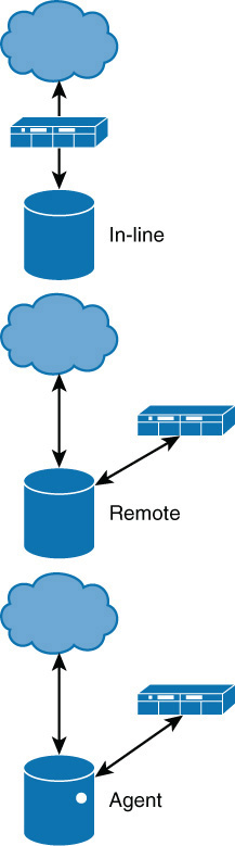
Placement of a DAM depends on how the DAM operates. In some cases, traffic is routed through a DAM before it reaches the database. In other solutions, the collector is given administrative access to the database, and it performs the monitoring remotely. Finally, some solutions install an agent directly on the database. These three placement options are shown in Figure 3-11.
Networking Devices
Network infrastructure devices play a role in the security of a network. To properly configure and maintain these devices securely, you must have a basic understanding of their operation. The following sections introduce these devices, and the later section “Advanced Configuration of Routers, Switches, and Other Network Devices” covers some specific steps to take to enhance the security of their operation.
Switches
Switches are intelligent and operate at layer 2 of the OSI model. We say they map to this layer because they make switching decisions based on MAC addresses, which reside at layer 2. This process is called transparent bridging (see Figure 3-12).
Switches improve performance over hubs because they eliminate collisions. Each switch port is in its own collision domain, while all ports of a hub are in the same collision domain. From a security standpoint, switches are more secure in that a sniffer connected to any single port will only be able to capture traffic destined for or originating from that port.
Some switches, however, are both routers and switches, and in that case, we call them layer 3 switches because they both route and switch.
When using switches, it is important to be aware that providing redundant connections between switches is desirable but can introduce switching loops, which can be devastating to the network. Most switches run Spanning Tree Protocol (STP) to prevent switching loops. You should ensure that a switch does this and that it is enabled.
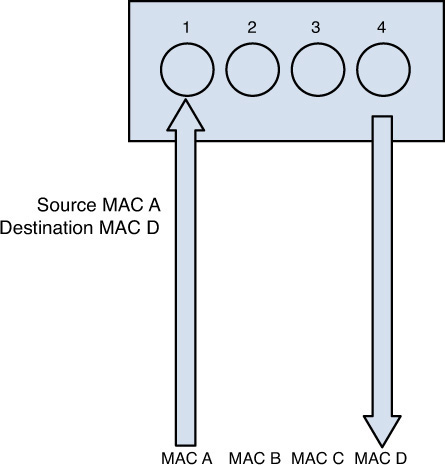
Preventing security issues with switches involves preventing MAC address overflow attacks. By design, switches place each port in its own collision domain, which is why a sniffer connected to a single port on a switch can only capture the traffic on that port and not other ports. However, an attack called a MAC address overflow attack can cause a switch to fill its MAC address table with nonexistent MAC addresses. Using free tools, a hacker can send thousands of nonexistent MAC addresses to the switch. The switch can only dedicate a certain amount of memory for the table, and at some point, it fills with the bogus MAC addresses. This prevents valid devices from creating content-addressable memory (CAM) entries (MAC addresses) in the MAC address table. When this occurs, all legitimate traffic received by the switch is flooded out every port. Remember, this is what switches do when they don’t find a MAC address in the table. Now the hackler can capture all the traffic. Figure 3-13 shows how this type of attack works.
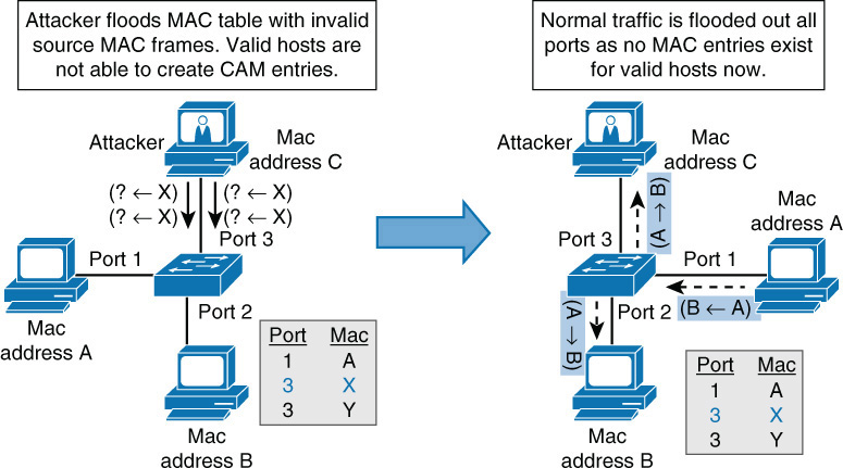
To prevent these attacks, you should limit the number of MAC addresses allowed on each port by using port security.
ARP Poisoning
One of the ways a man-in-the middle attack is accomplished is by poisoning the ARP cache on a switch. The attacker accomplishes this poison by answering ARP requests for another computer’s IP address with his own MAC address. Once the ARP cache has been successfully poisoned, when ARP resolution occurs, both computers will have the attacker’s MAC address listed as the MAC address that maps to the other computer’s IP address. As a result, both are sending to the attacker, placing him “in the middle.”
Two mitigation techniques are available for preventing ARP poisoning on a Cisco switch:
![]() Dynamic ARP inspection (DAI): This security feature intercepts all ARP requests and responses and compares each response’s MAC address and IP address information against the MAC–IP bindings contained in a trusted binding table. This table is built by also monitoring all DHCP requests for IP addresses and maintaining the mapping of each resulting IP address to a MAC address (which is a part of DHCP snooping). If an incorrect mapping is attempted, the switch rejects the packet.
Dynamic ARP inspection (DAI): This security feature intercepts all ARP requests and responses and compares each response’s MAC address and IP address information against the MAC–IP bindings contained in a trusted binding table. This table is built by also monitoring all DHCP requests for IP addresses and maintaining the mapping of each resulting IP address to a MAC address (which is a part of DHCP snooping). If an incorrect mapping is attempted, the switch rejects the packet.
![]() DHCP snooping: The main purpose of DHCP snooping is to prevent a poisoning attack on the DHCP database. This is not a switch attack per se, but one of its features can support DAI. It creates a mapping of IP addresses to MAC addresses from a trusted DHCP server that can be used in the validation process of DAI.
DHCP snooping: The main purpose of DHCP snooping is to prevent a poisoning attack on the DHCP database. This is not a switch attack per se, but one of its features can support DAI. It creates a mapping of IP addresses to MAC addresses from a trusted DHCP server that can be used in the validation process of DAI.
You must implement both DAI and DHCP snooping because DAI depend on DHCP snooping.
VLANs
Enterprise-level switches are capable of creating virtual local area networks (VLANs). These are logical subdivisions of a switch that segregate ports from one another as if they were in different LANs. VLANs can also span multiple switches, meaning that devices connected to switches in different parts of a network can be placed in the same VLAN, regardless of physical location.
A VLAN adds a layer of separation between sensitive devices and the rest of the network. For example, if only two devices should be able to connect to the HR server, the two devices and the HR server could be placed in a VLAN separate from the other VLANs. Traffic between VLANs can only occur through a router. Routers can be used to implement access control lists (ACLs) that control the traffic allowed between VLANs.
The advantages and disadvantages of deploying VLANs are listed in Table 3-10.

As you can see, the benefits of deploying VLANs far outweigh the disadvantages, but there are some VLAN attacks of which you should be aware. In particular, you need to watch out for VLAN hopping. By default, a switch port is an access port, which means it can only be a member of a single VLAN. Ports that are configured to carry the traffic of multiple VLANs, called trunk ports, are used to carry traffic between switches and to routers. An aim of a VLAN hopping attack is to receive traffic from a VLAN of which the hacker’s port is not a member. It can be done two ways:
![]() Switch spoofing: Switch ports can be set to use a negotiation protocol called Dynamic Trunking Protocol (DTP) to negotiate the formation of a trunk link. If an access port is left configured to use DTP, it is possible for a hacker to set his interface to spoof a switch and use DTP to create a trunk link. If this occurs, the hacker can capture traffic from all VLANs. To prevent this, you should disable DTP on all switch ports.
Switch spoofing: Switch ports can be set to use a negotiation protocol called Dynamic Trunking Protocol (DTP) to negotiate the formation of a trunk link. If an access port is left configured to use DTP, it is possible for a hacker to set his interface to spoof a switch and use DTP to create a trunk link. If this occurs, the hacker can capture traffic from all VLANs. To prevent this, you should disable DTP on all switch ports.
![]() Double tagging: Trunk ports use an encapsulation protocol called 802.1q to place a VLAN tag around each frame to identity the VLAN to which the frame belongs. When a switch at the end of a trunk link receives an 802.1q frame, it strips off that frame and forwards the traffic to the destination device. In a double tagging attack, the hacker creates a special frame that has two tags. The inner tag is the VLAN to which he wants to send a frame (perhaps with malicious content), and the outer tag is the real VLAN of which the hacker is a member. If the frame goes through two switches (which is possible because VLANs can span switches), the first tag gets taken off by the first switch, leaving the second switch, which allows the frame to be forwarded to the target VLAN.
Double tagging: Trunk ports use an encapsulation protocol called 802.1q to place a VLAN tag around each frame to identity the VLAN to which the frame belongs. When a switch at the end of a trunk link receives an 802.1q frame, it strips off that frame and forwards the traffic to the destination device. In a double tagging attack, the hacker creates a special frame that has two tags. The inner tag is the VLAN to which he wants to send a frame (perhaps with malicious content), and the outer tag is the real VLAN of which the hacker is a member. If the frame goes through two switches (which is possible because VLANs can span switches), the first tag gets taken off by the first switch, leaving the second switch, which allows the frame to be forwarded to the target VLAN.
Double tagging is only an issue on switches that use “native” VLANs. A native VLAN is used for any traffic that is still a member of the default VLAN, or VLAN 1. To mitigate double tagging, you can either move all ports out of VLAN 1 or change the number of the native VLAN from 1. If that is not possible, you can also enable the tagging of all traffic on the native VLAN. None of these settings are made by default, so you need to be actively in charge of this mitigation.
Firewalls
The network device that perhaps is most connected with the idea of security is the firewall. Firewalls can be software programs that are installed over server or client operating systems or appliances that have their own operating system. In either case, the job of a firewall is to inspect and control the type of traffic allowed.
Firewalls can be discussed on the basis of their type and their architecture. They can also be physical devices or can exist in a virtualized environment. The following sections look at them from all angles.
Types
When we discuss types of firewalls, we focus on the differences in the way they operate. Some firewalls make a more thorough inspection of traffic than others. Usually there is trade-off in the performance of the firewall and the type of inspection it performs. A deep inspection of the contents of the packets results in a firewall having a detrimental effect on throughput, while a more cursory look at each packet has somewhat less of a performance impact. To wisely select which traffic to inspect, you need to keep this trade-off in mind:
![]() Packet-filtering firewalls: These firewalls are the least detrimental to throughput as they only inspect the header of the packet for allowed IP addresses or port numbers. While performing this function slows traffic, it involves only looking at the beginning of the packet and making a quick decision to allow or disallow.
Packet-filtering firewalls: These firewalls are the least detrimental to throughput as they only inspect the header of the packet for allowed IP addresses or port numbers. While performing this function slows traffic, it involves only looking at the beginning of the packet and making a quick decision to allow or disallow.
While packet-filtering firewalls serve an important function, there are many attack types they cannot prevent. They cannot prevent IP spoofing, attacks that are specific to an application, attacks that depend on packet fragmentation, or attacks that take advantage of the TCP handshake. More advanced inspection firewall types are required to stop these attacks.
![]() Stateful firewalls: These firewalls are aware of the proper functioning of the TCP handshake, keep track of the state of all connections with respect to this process, and can recognize when packets are trying to enter the network that don’t make sense in the context of the TCP handshake.
Stateful firewalls: These firewalls are aware of the proper functioning of the TCP handshake, keep track of the state of all connections with respect to this process, and can recognize when packets are trying to enter the network that don’t make sense in the context of the TCP handshake.
In that process, a packet should never arrive at a firewall for delivery that has both the SYN flag and the ACK flag set, unless it is part of an existing handshake process, and it should be in response to a packet sent from inside the network with the SYN flag set. This is the type of packet that the stateful firewall would disallow. A stateful firewall also has the ability to recognize other attack types that attempt to misuse this process. It does this by maintaining a state table about all current connections and where each connection is in the process. This allows it to recognize any traffic that doesn’t make sense with the current state of the connections. Of course, maintaining this table and referencing the table cause this firewall type to have a larger effect on performance than does a packet-filtering firewall.
![]() Proxy firewalls: This type of firewall actually stands between an internal-to-external connection and makes the connection on behalf of the endpoints. Therefore, there is no direct connection. The proxy firewall acts as a relay between the two endpoints. Proxy firewalls can operate at two different layers of the OSI model:
Proxy firewalls: This type of firewall actually stands between an internal-to-external connection and makes the connection on behalf of the endpoints. Therefore, there is no direct connection. The proxy firewall acts as a relay between the two endpoints. Proxy firewalls can operate at two different layers of the OSI model:
![]() Circuit-level proxies operate at the session layer (layer 5) of the OSI model. This type of proxy makes decisions based on the protocol header and session layer information. Because it does no deep packet inspection (at layer 7, or the application layer), this type of proxy is considered application independent and can be used for wide range of layer 7 protocols. A SOCKS firewall is an example of a circuit-level firewall. It requires a SOCKS client on the computers. Many vendors have integrated their software with SOCKS to make it easier to use this type of firewall.
Circuit-level proxies operate at the session layer (layer 5) of the OSI model. This type of proxy makes decisions based on the protocol header and session layer information. Because it does no deep packet inspection (at layer 7, or the application layer), this type of proxy is considered application independent and can be used for wide range of layer 7 protocols. A SOCKS firewall is an example of a circuit-level firewall. It requires a SOCKS client on the computers. Many vendors have integrated their software with SOCKS to make it easier to use this type of firewall.
![]() Application-level proxies perform a type of deep packet inspection (inspection up to layer 7). This type of firewall understands the details of the communication process at layer 7 for the application. An application-level firewall maintains a different proxy function for each protocol. For example, the proxy will be able to read and filter HTTP traffic based on specific HTTP commands. Operating at this layer requires each packet to be completely opened and closed, giving this firewall the most impact on performance.
Application-level proxies perform a type of deep packet inspection (inspection up to layer 7). This type of firewall understands the details of the communication process at layer 7 for the application. An application-level firewall maintains a different proxy function for each protocol. For example, the proxy will be able to read and filter HTTP traffic based on specific HTTP commands. Operating at this layer requires each packet to be completely opened and closed, giving this firewall the most impact on performance.
![]() Dynamic packet-filtering: Although this isn’t actually a type of firewall, dynamic packet filtering is a process that a firewall may or may not handle and it is worth discussing here. When internal computers are attempting to establish a session with a remote computer, this process places both a source and destination port number in the packet. For example, if the computer is making a request of a web server, the destination will be port 80 because HTTP uses port 80 by default.
Dynamic packet-filtering: Although this isn’t actually a type of firewall, dynamic packet filtering is a process that a firewall may or may not handle and it is worth discussing here. When internal computers are attempting to establish a session with a remote computer, this process places both a source and destination port number in the packet. For example, if the computer is making a request of a web server, the destination will be port 80 because HTTP uses port 80 by default.
The source computer randomly selects the source port from the numbers available above the well-known port numbers or above 1023. Because it is impossible to predict what that random number will be, it is impossible to create a firewall rule that anticipates and allows traffic back through the firewall on that random port. A dynamic packet-filtering firewall keeps track of that source port and dynamically adds a rule to the list to allow return traffic to that port.
![]() Kernel proxy firewalls: This type of firewall is an example of a fifth-generation firewall. It inspects a packet at every layer of the OSI model but does not introduce the same performance hit as an application-layer firewall because it does this at the kernel layer. It also follows the proxy model in that it stands between two systems and creates connections on their behalf.
Kernel proxy firewalls: This type of firewall is an example of a fifth-generation firewall. It inspects a packet at every layer of the OSI model but does not introduce the same performance hit as an application-layer firewall because it does this at the kernel layer. It also follows the proxy model in that it stands between two systems and creates connections on their behalf.
The pros and cons of these firewall types are listed in Table 3-11.
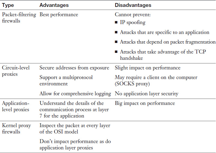
Although each scenario can be unique, the typical placement of each firewall type is shown in Table 3-12.

Firewall Architecture
Whereas the type of firewall speaks to the internal operation of the firewall, the architecture refers to the way in which firewalls are deployed in the network to form a system of protection. The following sections look at the various ways firewalls can be deployed.
A bastion host may or may not be a firewall. The term actually refers to the position of any device. If the device is exposed directly to the Internet or to any untrusted network while screening the rest of the network from exposure, it is a bastion host. Whether the bastion host is a firewall, a DNS server, or a web server, all standard hardening procedures are especially important because this device is exposed. Any unnecessary services should be stopped, all unneeded ports should be closed, and all security patches must be up to date. These procedures are referred to as reducing the attack surface. Some other examples of bastion hosts are FTP servers, DNS servers, web servers, and email servers.
In any case where a host must be publicly accessible from the Internet, the device must be treated as a bastion host, and you should take the following measures to protect these machines:
![]() Disable or remove all unnecessary services, protocols, programs, and network ports.
Disable or remove all unnecessary services, protocols, programs, and network ports.
![]() Use separate authentication services from trusted hosts within the network.
Use separate authentication services from trusted hosts within the network.
![]() Remove as many utilities and system configuration tools as is practical.
Remove as many utilities and system configuration tools as is practical.
![]() Install all appropriate service packs, hot fixes, and patches.
Install all appropriate service packs, hot fixes, and patches.
![]() Encrypt any local user account and password databases.
Encrypt any local user account and password databases.
A bastion host can be located in the following locations:
![]() Behind the exterior and interior firewalls: Locating it here and keeping it separate from the interior network complicates the configuration but is safest.
Behind the exterior and interior firewalls: Locating it here and keeping it separate from the interior network complicates the configuration but is safest.
![]() Behind the exterior firewall only: Perhaps the most common location for a bastion host is separated from the internal network; this means less complicated configuration (see Figure 3-14).
Behind the exterior firewall only: Perhaps the most common location for a bastion host is separated from the internal network; this means less complicated configuration (see Figure 3-14).

![]() As both the exterior firewall and a bastion host: This setup exposes the host to the most danger.
As both the exterior firewall and a bastion host: This setup exposes the host to the most danger.
Dual-Homed Firewalls
A dual-homed firewall has two network interfaces: one pointing to the internal network and another connected to the untrusted network. In many cases, routing between these interfaces is turned off. The firewall software will allow or deny traffic between the two interfaces based on the firewall rules configured by the administrator. The danger of relying on a single dual-homed firewall is that there is a single point of failure. If this device is compromised, the network is compromised, too. If it suffers a denial of service attack, no traffic will pass. Neither is a good situation.
The advantages of this setup include:
![]() The configuration is simple.
The configuration is simple.
![]() It’s possible to perform IP masquerading (NAT).
It’s possible to perform IP masquerading (NAT).
![]() It is less costly than using two firewalls
It is less costly than using two firewalls
Disadvantages include:
![]() There is a single point of failure.
There is a single point of failure.
![]() It is not as secure as other options.
It is not as secure as other options.
A dual-homed firewall (also called a dual-homed host) location is shown in Figure 3-15.
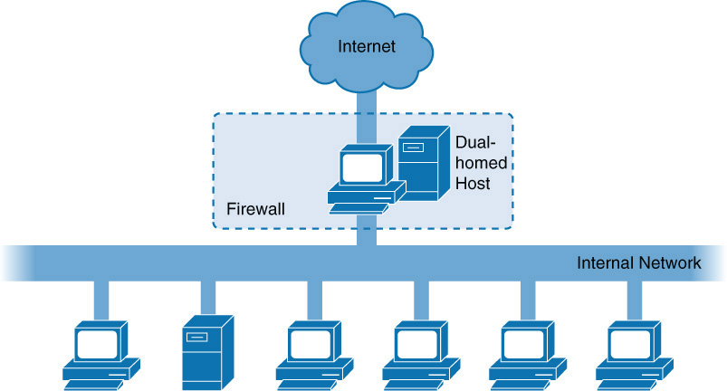
Multihomed Firewalls
A firewall may be multihomed. One popular type is the three-legged firewall. In this configuration, there are three interfaces: one connected to the untrusted network, one to the internal network, and the last to a part of the network called a demilitarized zone (DMZ), a protected network that contains systems that need a higher level of protection. A DMZ might contain web servers, email servers, or DNS servers. The firewall controls the traffic that flows between the three networks, being somewhat careful with traffic destined for the DMZ and treating traffic to the internal network with much more suspicion.
The advantages of a three-legged firewall include:
![]() They offer cost savings on devices, because you need only one firewall and not two or three.
They offer cost savings on devices, because you need only one firewall and not two or three.
![]() It is possible to perform IP masquerading (NAT) on the internal network while not doing so for the DMZ.
It is possible to perform IP masquerading (NAT) on the internal network while not doing so for the DMZ.
Among the disadvantages are:
![]() The complexity of the configuration is increased.
The complexity of the configuration is increased.
![]() There is a single point of failure.
There is a single point of failure.
The location of a three-legged firewall is shown in Figure 3-16.
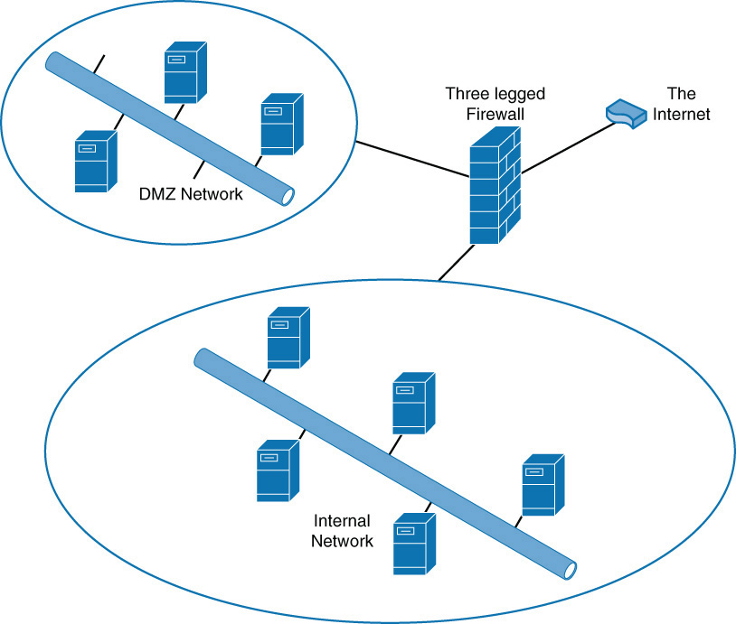
Screened Host Firewalls
While the firewalls discussed thus far typically connect directly to the untrusted network (at least one interface does), a screened host is a firewall that is between the final router and the internal network. When traffic comes into the router and is forwarded to the firewall, it is inspected before going into the internal network. This configuration is very similar to that of a dual-homed firewall; the difference is that the separation between the perimeter network and the internal network is logical and not physical. There is only a single interface.
The advantages to this solution include:
![]() It offers more flexibility than a dual-homed firewall because rules rather than an interface create the separation.
It offers more flexibility than a dual-homed firewall because rules rather than an interface create the separation.
![]() There are potential cost savings.
There are potential cost savings.
![]() The configuration is more complex.
The configuration is more complex.
![]() It is easier to violate the policies than with dual-homed firewalls.
It is easier to violate the policies than with dual-homed firewalls.
The location of a screened host firewall is shown in Figure 3-17.
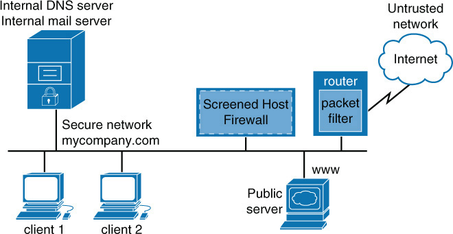
Screened Subnets
Taking the screened host concept a step further is a screened subnet. In this case, two firewalls are used, and traffic must be inspected at both firewalls before it can enter the internal network. This solution is called a screen subnet because there is a subnet between the two firewalls that can act as a DMZ for resources from the outside world.
The advantages of a screened subnet include:
![]() It offers the added security of two firewalls before the internal network.
It offers the added security of two firewalls before the internal network.
![]() One firewall is placed before the DMZ protecting the devices in the DMZ.
One firewall is placed before the DMZ protecting the devices in the DMZ.
Disadvantages include:
![]() It is more costly than using either a dual-homed or three-legged firewall.
It is more costly than using either a dual-homed or three-legged firewall.
![]() Configuring two firewalls adds complexity.
Configuring two firewalls adds complexity.
Figure 3-18 shows the placement of the firewalls to create a screened subnet.

In any situation where multiple firewalls are in use, such as an active/passive cluster of two firewalls, care should be taken to ensure that TCP sessions are not traversing one firewall while return traffic of the same session is traversing the other. When stateful filtering is being performed, the return traffic will be denied breaking, which will break the user connection.
In the real world, the various firewall approaches are mixed and matched to meet requirements. So you may find elements of all of these architectural concepts being applied to a specific situation.
Wireless Controllers
Wireless controllers are centralized appliances or software packages that monitor, manage, and control multiple wireless access points. Wireless controller architecture is shown in Figure 3-19.
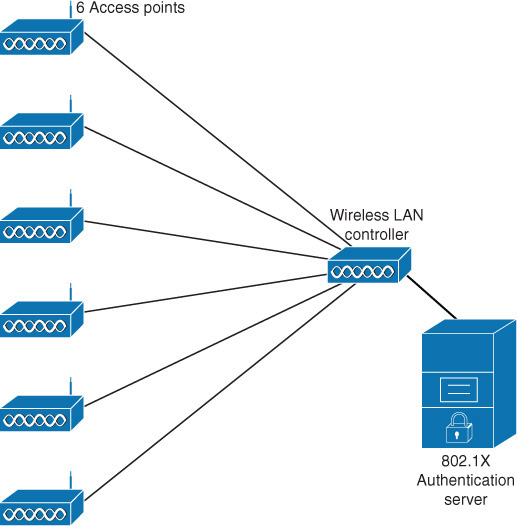
WLAN controllers include many security features that are not possible with access points (APs) operating independently of one another. Some of these features include:
![]() Interference detection and avoidance: This is achieved by adjusting the channel assignment and RF power in real time.
Interference detection and avoidance: This is achieved by adjusting the channel assignment and RF power in real time.
![]() Load balancing: You can use load balancing to connect a single user to multiple APs for better coverage and data rate.
Load balancing: You can use load balancing to connect a single user to multiple APs for better coverage and data rate.
![]() Coverage gap detection: This type of detection can increase the power to cover holes that appear in real time.
Coverage gap detection: This type of detection can increase the power to cover holes that appear in real time.
WLAN controllers also support forms of authentication such as 802.1x, Protected Extensible Authentication Protocol (PEAP), Lightweight Extensible Authentication Protocol (LEAP), Extensible Authentication Protocol–Transport Layer Protocol (EAP-TLS), Wi-Fi Protected Access (WPA), 802.11i (WPA2), and Layer 2 Tunneling Protocol (L2TP).
While in the past wireless access points operated as standalone devices, the move to wireless controllers that manage multiple APs gives many benefits over using standalone APs. Among them are:
![]() Ability to manage the relative strengths of the radio waves to provide backup and to reduce inference between APs
Ability to manage the relative strengths of the radio waves to provide backup and to reduce inference between APs
![]() More seamless roaming between APs
More seamless roaming between APs
![]() Real-time control of access points
Real-time control of access points
![]() Centralized authentication
Centralized authentication
The disadvantages are:
![]() More costly
More costly
![]() More complex configuration
More complex configuration
Figure 3-20 shows the layout of a WLAN using a controller, and Figure 3-21 shows a layout of a WLAN not using a controller.
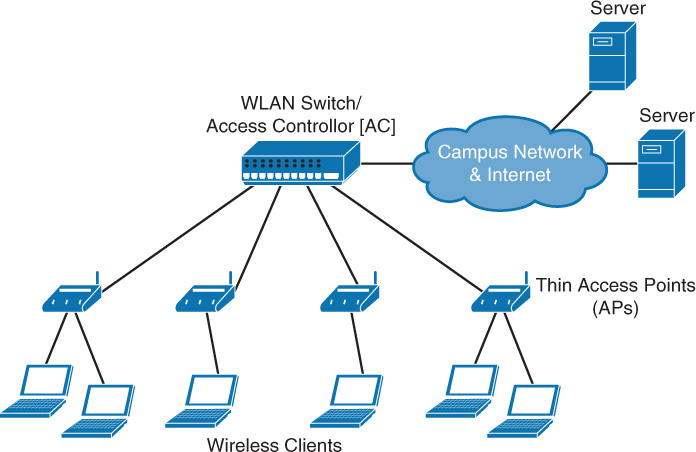
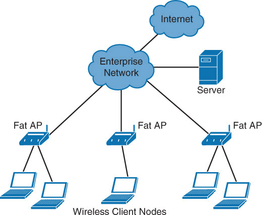
Routers
Routers operate at layer 3 when we are discussing the routing function in isolation. Some routing devices can combine routing functionality with switching and layer 4 filtering. But because routing uses layer 3 information (IP addresses) to make decisions, it is a layer 3 function.
Routers use a routing table that tells the router in which direction to send traffic destined for a particular network. Although routers can be configured with routes to individual computers, typically they route toward networks, not toward individual computers. When a packet arrives at a router that is directly connected to the destination network, that particular router will perform an ARP broadcast to learn the MAC address of the computer and send the packet as a frame at layer 2.
Routers perform an important security function in that ACLs are typically configured on them. ACLs are ordered sets of rules that control the traffic that is permitted or denied the use of a path through the router. These rules can operate at layer 3, making these decisions on the basis of IP addresses, or at layer 4, when only certain types of traffic are allowed. An ACL typically references a port number of the service or application that is allowed or denied.
To secure a router, you need to ensure that the following settings are in place:
![]() Configure authentication between your routers to prevent performing routing updates with rouge routers.
Configure authentication between your routers to prevent performing routing updates with rouge routers.
![]() Secure the management interfaces with strong passwords.
Secure the management interfaces with strong passwords.
![]() Manage routers with SSH rather than Telnet.
Manage routers with SSH rather than Telnet.
Proxies
Proxy servers can be appliances, or they can be software that is installed on a server operating system. These servers act like a proxy firewall in that they create the web connection between systems on their behalf, but they can typically allow and disallow traffic on a more granular basis. For example, a proxy server may allow the Sales group to go to certain websites while not allowing the Data Entry group access to those same sites. The functionality extends beyond HTTP to other traffic type, such as FTP traffic.
Proxy servers can provide an additional beneficial function called web caching. When a proxy server is configured to provide web caching, it saves a copy of all web pages that have been delivered to internal computers in a web cache. If any user requests the same page later, the proxy server has a local copy and need not spend the time and effort to retrieve it from the Internet. This greatly improves web performance for frequently requested pages.
Ports
As a CASP candidate, it is very important that you know the port numbers of both secure and insecure services and applications. In cases where you need to block or allow a traffic type, you need to know the port number of the traffic type. Table 3-13 lists important port numbers you should know.
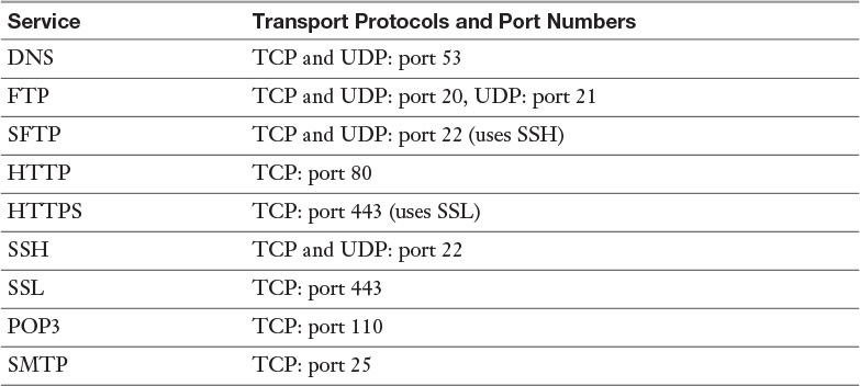
Virtual Networking and Security Components
Increasingly, devices and services are being virtualized, and many of the infrastructure devices that support the network are being virtualized as well and are operating in these virtual environments. Many of the devices listed under the section “Networking Devices” can be virtualized. The following sections briefly look at a few.
Virtual Switches
Virtual switches are software applications or programs that offer switching functionality to devices located in a virtual network. They provide a connection point to the network for virtualized end devices while also providing a connection to a physical switch from the virtual network. This relationship is shown in Figure 3-22.
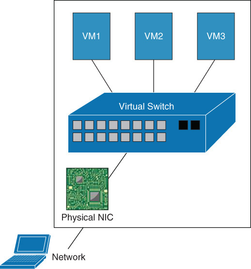
The advantages of virtual switches include:
![]() They make it possible to ensure the integrity of the network and security settings of a VM when the VM is migrated across physical hosts.
They make it possible to ensure the integrity of the network and security settings of a VM when the VM is migrated across physical hosts.
![]() They support VLANs and trunking so they can integrate in a network with physical switches.
They support VLANs and trunking so they can integrate in a network with physical switches.
![]() They do not support uplinks to physical switches, eliminating the need for Spanning Tree Protocol (STP).
They do not support uplinks to physical switches, eliminating the need for Spanning Tree Protocol (STP).
![]() They do not support STP or DTP, which allows for management without the help of the network administrator.
They do not support STP or DTP, which allows for management without the help of the network administrator.
![]() They do not need to learn MAC addresses as physical switches do.
They do not need to learn MAC addresses as physical switches do.
![]() There is an additional processing load on physical hosts.
There is an additional processing load on physical hosts.
![]() They lack of familiar management options such as SSH.
They lack of familiar management options such as SSH.
![]() The learning curve for technicians can be steep.
The learning curve for technicians can be steep.
![]() They don’t support all the features of a physical switch, such as Port Aggregation Protocol (PAgP).
They don’t support all the features of a physical switch, such as Port Aggregation Protocol (PAgP).
The security issues with a virtual switch are not too different from those of a physical switch. MAC address spoofing is still a concern. The good news is that most virtual switches support disallowing any changes to MAC addresses of VMs. In some cases, you may need to allow this behavior, such as when VMs are operating in a network load balancing scenario. You can control this per port on the virtual switch.
Virtual Firewalls
Another example of a virtualized device is a virtual firewall. Virtual firewalls are software that has been specifically written to operate in the virtual environment. Virtualization vendors such as VMware are increasingly making part of their code available to security vendors to create firewalls (and antivirus products) that integrate closely with the product.
Advantages of virtual firewalls include:
![]() They offer cost savings.
They offer cost savings.
![]() They are easy to implement.
They are easy to implement.
![]() Their simple functionality reduces integration issues.
Their simple functionality reduces integration issues.
Disadvantages include:
![]() There is a performance load on the CPU of the host.
There is a performance load on the CPU of the host.
![]() Network paths may potentially be suboptimal.
Network paths may potentially be suboptimal.
Virtual Wireless Controllers
A virtual wireless controller can be deployed on a server as software. It provides all the functions of a physical controller. It provides the following advantages:
![]() It shares the existing virtual infrastructure, leading to cost savings.
It shares the existing virtual infrastructure, leading to cost savings.
![]() It can secure virtualization features such as moving VMs between hosts.
It can secure virtualization features such as moving VMs between hosts.
![]() It can be deployed quickly.
It can be deployed quickly.
Security guidelines with virtual WLAN controllers are the same as with physical controllers and include:
![]() Secure all management interfaces with strong authentication.
Secure all management interfaces with strong authentication.
![]() Deploy all available security features, including rogue AP and client detection and mitigation.
Deploy all available security features, including rogue AP and client detection and mitigation.
Virtual Routers
Virtual routers are actually software instances of physical routers and in some implementations are instances that operate inside a physical router. Traditionally, routers contribute to a single routing table, but when multiple virtual routers are created on a physical router, each has its own routing table. Service providers use these to separate customer networks from one another.
While virtual routers offer some advantages, the following limitations also exist:
![]() If the virtualization infrastructure goes down, troubleshooting requires physically visiting the location.
If the virtualization infrastructure goes down, troubleshooting requires physically visiting the location.
![]() Virtual routers are more prone to configuration errors than are physical routers.
Virtual routers are more prone to configuration errors than are physical routers.
Virtual Proxy Servers
Virtual proxy servers, like their physical counterparts, act as intermediaries for requests from clients seeking resources from other servers. There are no differences between securing actual and virtual servers. See the treatment of proxy servers in the section “Networking Devices.”
Virtual Computing
Virtual computing offers the option of presenting standard controlled images to users. These images can be used to ensure consistency in versioning of both operating system and applications, provide easier patching and updating, and ensure consistent application of security controls.
Keep in mind that in any virtual environment, each virtual server that is hosted on the physical server must be configured with its own security mechanisms. These mechanisms include antivirus and antimalware software and all the latest service packs and security updates for all the software hosted on the virtual machine. Also remember that all the virtual servers share the resources of the physical device.
Complex Network Security Solutions for Data Flow
While securing the information that traverses the network is probably the most obvious duty of the security professional, having an awareness of the type of traffic that is generated on the network is just as important. For both security and performance reasons, you need to understand the amount of various traffic types and the source of each type of traffic. The following sections talk about what data flows are and how to protect sensitive flows.
SSL Inspection
One form of traffic on which it is difficult to perform deep packet inspection for malware and malicious commands is SSL protected traffic. One method of doing so is using a proxy server that supports SSL inspection.
When SSL inspection is in use, the proxy server intercepts all SSL traffic, decrypts it, inspects it, and re-encrypts it. This process is depicted in Figure 3-23.
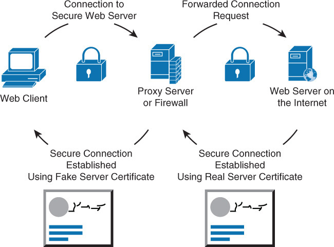
Network Flow Data
A network flow is a single conversation or session that shares certain characteristics between two devices. Tools and utilities such as Cisco’s NetFlow Analyzer can organize these conversations for proposes of traffic analysis and planning. You can set tools like this to define the conversations on the basis of various combinations of the following characteristics:
![]() Ingress interface
Ingress interface
![]() Source IP address
Source IP address
![]() Destination IP address
Destination IP address
![]() IP protocol
IP protocol
![]() Source port for UDP or TCP
Source port for UDP or TCP
![]() Destination port for UDP or TCP and type and code for ICMP (with type and code set as 0 for protocols other than ICMP)
Destination port for UDP or TCP and type and code for ICMP (with type and code set as 0 for protocols other than ICMP)
![]() IP type of service
IP type of service
The most Net flow identifiers are source and destination IP addresses and source and destination port numbers. You can use the nfdump command-line tool to extract network flow information for a particular flow or conversation. Here is an example:
Date flow start Duration Proto Src IP Addr:Port Dst IP Addr:Port Packets Bytes Flows
2010-09-01 00:00:00.459 0.000 UDP 127.0.0.1:24920 -> 192.168.0.1:22126 1 46 1
2010-09-01 00:00:00.363 0.000 UDP 192.168.0.1:22126 -> 127.0.0.1:24920 1 80 1
In this example, in the first flow, a packet is sent from the host machine using 127.0.0.1 with a port number of 24920 to a machine at 192.168.0.1 directed to port 22126. The second flow is the response from the device at 192.168.0.1 to the original source port of 24920.
Tools like this usually provide the ability to identify the top five protocols in use, the top five speakers on the network, and the top five flows or conversions. Moreover, they can graph this information, which makes identifying patterns easier.
Secure Configuration and Baselining of Networking and Security Components
To take advantage of all the available security features on the various security devices discussed in this chapter, proper configuration and management of configurations must take place. This requires a consistent change process and some method of restricting administrative access to devices. The following sections explore both issues.
ACLs
ACLs are rule sets that can be implemented on firewalls, switches, and other infrastructure devices to control access. There are other uses of ACLs, such as to identify traffic for the purpose of applying Quality of Service (QoS), but the focus here is on using ACLs to restrict access to the devices.
Many of the devices in question have web interfaces that can be used for management, but many are also managed through a command-line interface (and many technicians prefer this method). ACLs can be applied to these virtual terminal interfaces to control which users (based on their IP addresses) have access and which do not.
When creating ACL rule sets, keep the following design considerations in mind:
![]() The order of the rules is important. If traffic matches a rule, the action specified by the rule will be applied, and no other rules will be read. Place more specific rules at the top of the list and more general rules at the bottom.
The order of the rules is important. If traffic matches a rule, the action specified by the rule will be applied, and no other rules will be read. Place more specific rules at the top of the list and more general rules at the bottom.
![]() On many devices (such as Cisco routers), an implied deny all rule is located at the end of all ACLs. If you are unsure, it is always best to configure an explicit deny all rule at the end of an ACL list.
On many devices (such as Cisco routers), an implied deny all rule is located at the end of all ACLs. If you are unsure, it is always best to configure an explicit deny all rule at the end of an ACL list.
![]() It is also possible to log all traffic that meets any of the rules.
It is also possible to log all traffic that meets any of the rules.
Creating Rule Sets
Firewalls use rule sets to do their job. They can be created at the command line or in a GUI. As a CASP candidate, you must understand the logic that a device uses to process the rules. The rules are examined starting at the top of the list of rules, in this order:
![]() The type of traffic
The type of traffic
![]() The source of the traffic
The source of the traffic
![]() The destination of the traffic
The destination of the traffic
![]() The action to take on the traffic
The action to take on the traffic
For example, the following rule denies HTTP traffic from the device at 192.168.5.1 if it is destined for the device at 10.6.6.6. It is created as an access list on a Cisco router:
Access-list 101 deny tcp host 192.168.5.1 host 10.6.6.6 eq www
If the first rule in a list doesn’t match the traffic in question, the next rule in the list is examined. If all the rules are examined and none of them match the traffic type in a packet, the traffic will be denied by a rule called the implicit deny rule. Therefore, if a list doesn’t contain at least one permit statement, all traffic will be denied.
While ACLs can be part of a larger access control policy, you shouldn’t lose sight of the fact that you need to also use a secure method to work at the command line. You should therefore use SSH instead of Telnet because Telnet is cleartext, while SSH is not.
Change Monitoring
All networks evolve, grow, and change over time. Companies and their processes also evolve and change, which is a good thing. But change should be managed in a structured way to maintain a common sense of purpose about the changes. By following recommended steps in a formal process, you can prevent change from becoming the tail that wags the dog. The following guidelines should be a part of any change control policy:
![]() All changes should be formally requested.
All changes should be formally requested.
![]() Each request should be analyzed to ensure that it supports all goals and polices.
Each request should be analyzed to ensure that it supports all goals and polices.
![]() Prior to formal approval, all costs and effects of the methods of implementation should be reviewed.
Prior to formal approval, all costs and effects of the methods of implementation should be reviewed.
![]() Once approved, the change steps should be developed
Once approved, the change steps should be developed
![]() During implementation, incremental testing should occur, relying on a predetermined fallback strategy if necessary.
During implementation, incremental testing should occur, relying on a predetermined fallback strategy if necessary.
![]() Complete documentation should be produced and submitted with a formal report to management.
Complete documentation should be produced and submitted with a formal report to management.
One of the key benefits of following this method is the ability to make use of the documentation in future planning. Lessons learned can be applied, and even the process itself can be improved through analysis.
In summary, these are the steps in a formal change control process:
1. Submit/resubmit a change request.
2. Review the change request.
3. Coordinate the change.
4. Implement the change.
5. Measure the results of the change.
Configuration Lockdown
Configuration lockdown (sometimes also called system lockdown) is a setting that can be implemented on devices including servers, routers, switches, firewalls, and virtual hosts. You set it on a device once that device is correctly configured. It prevents any changes to the configuration, even by users who formerly had the right to configure the device. This setting helps support change control.
Full testing for functionality of all services and applications should be performed prior to implementing this setting. Many products that provide this functionality offer a test mode, in which you can log any problems the current configuration causes without allowing the problems to completely manifest on the network. This allows you to identify and correct any problems prior to implementing full lockdown.
Availability Controls
While security operations seem to focus attention on providing confidentiality and integrity of data, availability of the data is also one of its goals. This means designing and maintaining processes and systems that maintain availability to resources despite hardware or software failures in the environment. Availability controls comprise a set of features or steps taken to ensure that a resource is available for use. It also has its own set of tools to achieve this goal and metrics to measure effectiveness, including the following:
![]() Redundant hardware: Failure of physical components, such as hard drives and network cards, can interrupt access to resources. Providing redundant instances of these components can help ensure faster return to access. In some cases, redundancy may require manual intervention to change out a component, but in many cases, these items are hot swappable (that is, they can be changed with the device up and running), in which case there may be a momentary reduction in performance rather than a complete disruption of access. While the advantage of redundant hardware is more availability, the disadvantage is the additional cost and in some cases the opportunity cost of a device never being used unless there is a failure.
Redundant hardware: Failure of physical components, such as hard drives and network cards, can interrupt access to resources. Providing redundant instances of these components can help ensure faster return to access. In some cases, redundancy may require manual intervention to change out a component, but in many cases, these items are hot swappable (that is, they can be changed with the device up and running), in which case there may be a momentary reduction in performance rather than a complete disruption of access. While the advantage of redundant hardware is more availability, the disadvantage is the additional cost and in some cases the opportunity cost of a device never being used unless there is a failure.
![]() Fault-tolerant technologies: Taking the idea of redundancy to the next level are technologies that are based on multiple computing systems or devices working together to provide uninterrupted access, even in the event of a failure of one of the systems. Clustering of servers and grid computing are both great examples of this approach. As with redundant hardware, many fault-tolerant technologies result in devices serving only as backups and not typically being utilized.
Fault-tolerant technologies: Taking the idea of redundancy to the next level are technologies that are based on multiple computing systems or devices working together to provide uninterrupted access, even in the event of a failure of one of the systems. Clustering of servers and grid computing are both great examples of this approach. As with redundant hardware, many fault-tolerant technologies result in devices serving only as backups and not typically being utilized.
A number of metrics are used to measure and control availability, including the following:
![]() Service-level agreements (SLAs): SLAs are agreements about the ability of the support system to respond to problems within a certain time frame while providing an agreed level of service. These agreements can be internal between departments or external, with a service provider. Agreeing on the quickness with which various problems are addressed introduces some predictability to the response to problems; this ultimately supports the maintenance of access to resources. The following are some examples of what may be included in an SLA:
Service-level agreements (SLAs): SLAs are agreements about the ability of the support system to respond to problems within a certain time frame while providing an agreed level of service. These agreements can be internal between departments or external, with a service provider. Agreeing on the quickness with which various problems are addressed introduces some predictability to the response to problems; this ultimately supports the maintenance of access to resources. The following are some examples of what may be included in an SLA:
![]() Loss of connectivity to the DNS server must be restored within a two-hour period.
Loss of connectivity to the DNS server must be restored within a two-hour period.
![]() Loss of connectivity to Internet service must be restored in a five-hour period.
Loss of connectivity to Internet service must be restored in a five-hour period.
![]() Loss of connectivity of a host machine must be restored in an eight-hour period.
Loss of connectivity of a host machine must be restored in an eight-hour period.
![]() MTBF and MTTR: SLAs are appropriate for services that are provided, but a slightly different approach to introducing predictability can be used with regard to physical components that are purchased. Vendors typically publish values for a product’s mean time between failures (MTBF), which describes the average amount of time between failures during normal operations. Another valuable metric typically provided is the mean time to repair (MTTR), which describes the average amount of time it will take to get the device fixed and back online.
MTBF and MTTR: SLAs are appropriate for services that are provided, but a slightly different approach to introducing predictability can be used with regard to physical components that are purchased. Vendors typically publish values for a product’s mean time between failures (MTBF), which describes the average amount of time between failures during normal operations. Another valuable metric typically provided is the mean time to repair (MTTR), which describes the average amount of time it will take to get the device fixed and back online.
CASP candidates must understand a variety of high-availability terms and techniques, including the following:
![]() Redundant Array of Inexpensive/Independent Disks (RAID): RAID is a hard drive technology in which data is written across multiple disks in such a way that a disk can fail and the data can be quickly made available by remaking disks in the array without resorting to a backup tape. The most common types of RAID are:
Redundant Array of Inexpensive/Independent Disks (RAID): RAID is a hard drive technology in which data is written across multiple disks in such a way that a disk can fail and the data can be quickly made available by remaking disks in the array without resorting to a backup tape. The most common types of RAID are:
![]() RAID 0: Also called disk striping, this method writes the data across multiple drives. While it improves performance, it does not provide fault tolerance. RAID 0 is depicted in Figure 3-24.
RAID 0: Also called disk striping, this method writes the data across multiple drives. While it improves performance, it does not provide fault tolerance. RAID 0 is depicted in Figure 3-24.
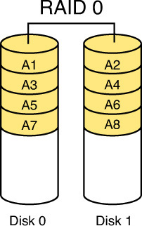
![]() RAID 1: Also called disk mirroring, RAID 1 uses two disks and writes a copy of the data to both disks, providing fault tolerance in the case of a single drive failure. RAID 1 is depicted in Figure 3-25.
RAID 1: Also called disk mirroring, RAID 1 uses two disks and writes a copy of the data to both disks, providing fault tolerance in the case of a single drive failure. RAID 1 is depicted in Figure 3-25.
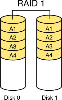
![]() RAID 3: This method, which requires at least three drives, writes the data across all drives, as with striping, and then writes parity information to a single dedicated drive. The parity information is used to regenerate the data in the case of a single drive failure. The downfall of this method is that the parity drive is a single point of failure. RAID 3 is depicted in Figure 3-26.
RAID 3: This method, which requires at least three drives, writes the data across all drives, as with striping, and then writes parity information to a single dedicated drive. The parity information is used to regenerate the data in the case of a single drive failure. The downfall of this method is that the parity drive is a single point of failure. RAID 3 is depicted in Figure 3-26.
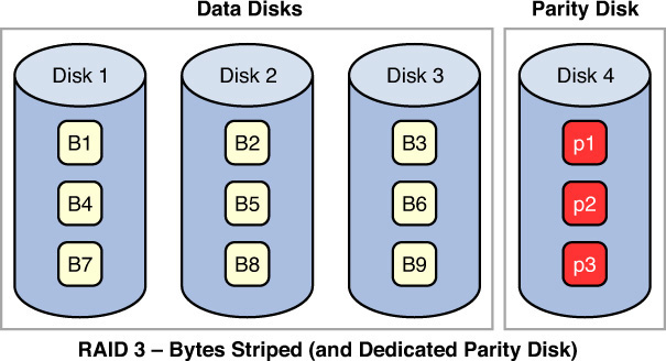
![]() RAID 5: This method, which requires at least three drives, writes the data across all drives, as with striping, and then writes parity information across all drives as well. The parity information is used in the same way as in RAID 3, but it is not stored on a single drive, so there is no single point of failure for the parity data. With hardware RAID 5, the spare drives that replace the failed drives are usually hot swappable, meaning they can be replaced on the server while it is running. RAID 5 is depicted in Figure 3-27.
RAID 5: This method, which requires at least three drives, writes the data across all drives, as with striping, and then writes parity information across all drives as well. The parity information is used in the same way as in RAID 3, but it is not stored on a single drive, so there is no single point of failure for the parity data. With hardware RAID 5, the spare drives that replace the failed drives are usually hot swappable, meaning they can be replaced on the server while it is running. RAID 5 is depicted in Figure 3-27.
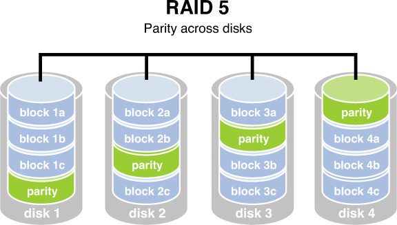
![]() RAID 7: While not a standard but a proprietary implementation, this system incorporates the same principles as RAID 5 but enables the drive array to continue to operate if any disk or any path to any disk fails. The multiple disks in the array operate as a single virtual disk.
RAID 7: While not a standard but a proprietary implementation, this system incorporates the same principles as RAID 5 but enables the drive array to continue to operate if any disk or any path to any disk fails. The multiple disks in the array operate as a single virtual disk.
While RAID can be implemented with software or with hardware, certain types of RAID are faster when implemented with hardware. When software RAID is used, it is a function of the operating system. Both RAID 3 and 5 are examples of RAID types that are faster when implemented with hardware. Simple striping and mirroring (RAID 0 and 1), however, tend to perform well in software because they do not use the hardware-level parity drives. Table 3-14 summarizes the RAID types
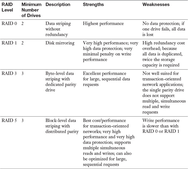
![]() Storage area networks (SANs): These high-capacity storage devices are connected by a high-speed private network, using storage-specific switches. This technology is discussed in Chapter 2, “Enterprise Storage.”
Storage area networks (SANs): These high-capacity storage devices are connected by a high-speed private network, using storage-specific switches. This technology is discussed in Chapter 2, “Enterprise Storage.”
![]() Failover: This is the capacity of a system to switch over to a backup system if a failure in the primary system occurs.
Failover: This is the capacity of a system to switch over to a backup system if a failure in the primary system occurs.
![]() Failsoft: This is the capability of a system to terminate noncritical processes when a failure occurs.
Failsoft: This is the capability of a system to terminate noncritical processes when a failure occurs.
![]() Clustering: This refers to a software product that provides load balancing services. With clustering, one instance of an application server acts as a master controller and distributes requests to multiple instances, using round-robin, weighted-round-robin, or a least-connections algorithm.
Clustering: This refers to a software product that provides load balancing services. With clustering, one instance of an application server acts as a master controller and distributes requests to multiple instances, using round-robin, weighted-round-robin, or a least-connections algorithm.
![]() Load balancing: Hardware products provide load balancing services. Application delivery controllers (ADCs) support the same algorithms but also use complex number-crunching processes, such as per-server CPU and memory utilization, fastest response times, and so on, to adjust the balance of the load. Load balancing solutions are also referred to as farms or pools.
Load balancing: Hardware products provide load balancing services. Application delivery controllers (ADCs) support the same algorithms but also use complex number-crunching processes, such as per-server CPU and memory utilization, fastest response times, and so on, to adjust the balance of the load. Load balancing solutions are also referred to as farms or pools.
![]() Single point of failure (SPOF): While not actually a strategy, it is worth mentioning that the ultimate goal of any of the approaches described here is to avoid a single point of failure in a system. All components and groups of components and devices should be examined to discover any single element that could interrupt access to resources if a failure occurs. Then each SPOF should be mitigated in some way. For example, if you have a single high-speed Internet connection, you might decide to implement another lower-speed connection just to provide backup in case the primary connection goes down. This is especially important for ecommerce servers.
Single point of failure (SPOF): While not actually a strategy, it is worth mentioning that the ultimate goal of any of the approaches described here is to avoid a single point of failure in a system. All components and groups of components and devices should be examined to discover any single element that could interrupt access to resources if a failure occurs. Then each SPOF should be mitigated in some way. For example, if you have a single high-speed Internet connection, you might decide to implement another lower-speed connection just to provide backup in case the primary connection goes down. This is especially important for ecommerce servers.
Software-Defined Networking
In a network, three planes typically form the networking architecture:
![]() Control plane: This plane carries signaling traffic originating from or destined for a router. This is the information that allows routers to share information and build routing tables.
Control plane: This plane carries signaling traffic originating from or destined for a router. This is the information that allows routers to share information and build routing tables.
![]() Data plane: Also known as the forwarding plane, this plane carries user traffic.
Data plane: Also known as the forwarding plane, this plane carries user traffic.
![]() Management plane: This plane administers the router.
Management plane: This plane administers the router.
Software-defined networking (SDN) has been classically defined as the decoupling of the control plane and the data plane in networking. In a conventional network, these planes are implemented in the firmware of routers and switches. SDN implements the control plane in software, which enables programmatic access to it.
This definition has evolved over time to focus more on providing programmatic interfaces to networking equipment and less on the decoupling of the control and data planes. An example of this is the provision of APIs by vendors into the multiple platforms they sell.
One advantage of SDN is that it enables very detailed access into, and control over, network elements. It allows IT organizations to replace a manual interface with a programmatic one that can enable the automation of configuration and policy management.
An example of the use of SDN is using software to centralize the control plane of multiple switches that normally operate independently. (While the control plane normally functions in hardware, with SDN it is performed in software.) This concept is shown in Figure 3-28.
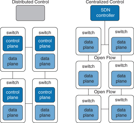
The advantages of SDN include:
![]() It is simple to mix and match solutions from different vendors.
It is simple to mix and match solutions from different vendors.
![]() SDN offers choice, speed, and agility in deployment.
SDN offers choice, speed, and agility in deployment.
The disadvantages of SDN include:
![]() Loss of connectivity to the controller brings down the entire network.
Loss of connectivity to the controller brings down the entire network.
![]() SDN can potentially allow attacks on the controller.
SDN can potentially allow attacks on the controller.
Cloud-Managed Networks
Cloud computing is all the rage these days, and it comes in many forms. The basic idea of cloud computing is to make resources available in a web-based data center so the resources can be accessed from anywhere. When a company pays another company to host and manage this type of environment, we call it a public cloud solution. If the company hosts this environment itself, we call it a private cloud solution.
There is trade-off to consider when a decision must be made between the two architectures. A private solution provides the most control over the safety of your data but also requires the staff and the knowledge to deploy, manage, and secure the solution. A public cloud puts your data’s safety in the hands of a third party, but that party is more capable and knowledgeable about protecting data in such an environment and managing the cloud environment.
With a public solution, various levels of service can be purchased. Some of these levels include:
![]() Infrastructure as a Service (IaaS): With IaaS, the vendor provides the hardware platform or data center, and the company installs and manages its own operating systems and application systems. The vendor simply provides access to the data center and maintains that access. An example of this is a company hosting all its web servers with a third party that provides everything. With IaaS, customers can benefit from the dynamic allocation of additional resources in times of high activity, while those same resources are scaled back when not needed, saving money.
Infrastructure as a Service (IaaS): With IaaS, the vendor provides the hardware platform or data center, and the company installs and manages its own operating systems and application systems. The vendor simply provides access to the data center and maintains that access. An example of this is a company hosting all its web servers with a third party that provides everything. With IaaS, customers can benefit from the dynamic allocation of additional resources in times of high activity, while those same resources are scaled back when not needed, saving money.
![]() Platform as a Service (PaaS): With PaaS, the vendor provides the hardware platform or data center and the software running on the platform, including the operating systems and infrastructure software. The company is still involved in managing the system. An example of this is a company that contacts a third party to provide a development platform for internal developers to use for development and testing.
Platform as a Service (PaaS): With PaaS, the vendor provides the hardware platform or data center and the software running on the platform, including the operating systems and infrastructure software. The company is still involved in managing the system. An example of this is a company that contacts a third party to provide a development platform for internal developers to use for development and testing.
![]() Software as a Service (SaaS): With SaaS, the vendor provides the entire solution, including the operating system, the infrastructure software, and the application. The vendor may provide an email system, for example, in which it hosts and manages everything for the contracting company. An example of this is a company that contracts to use Salesforce or Intuit QuickBooks using the browser rather than installing the applications on every machine. This frees the customer company from performing updates and other maintenance of the applications.
Software as a Service (SaaS): With SaaS, the vendor provides the entire solution, including the operating system, the infrastructure software, and the application. The vendor may provide an email system, for example, in which it hosts and manages everything for the contracting company. An example of this is a company that contracts to use Salesforce or Intuit QuickBooks using the browser rather than installing the applications on every machine. This frees the customer company from performing updates and other maintenance of the applications.
The relationship of these services to one another is shown in Figure 3-29.
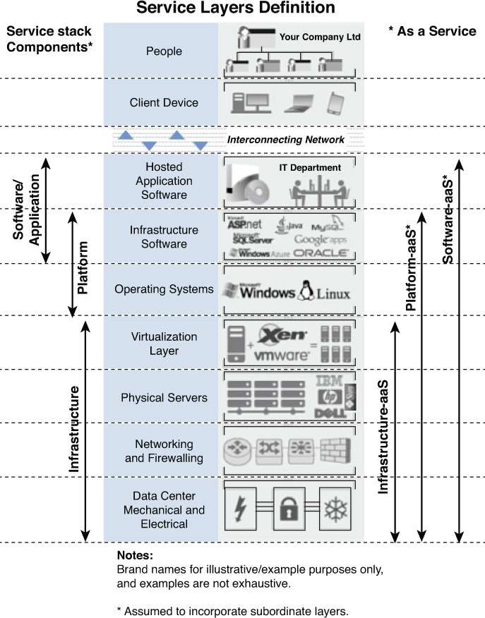
Network Management and Monitoring Tools
Network management and monitoring tools are essential elements of a security solution. This chapter covers many common network management and monitoring tools, including IDS and NIPS. Additional tools including the following:
![]() Network intrusion detection systems (NIDS): NIDS, covered in more detail in the section “Security Devices,” earlier in this chapter, are designed to monitor network traffic and detect and report threats. They use a variety of methods to discover threats, including:
Network intrusion detection systems (NIDS): NIDS, covered in more detail in the section “Security Devices,” earlier in this chapter, are designed to monitor network traffic and detect and report threats. They use a variety of methods to discover threats, including:
![]() Signature-based detection, which compares traffic with preconfigured attack patterns known as signatures.
Signature-based detection, which compares traffic with preconfigured attack patterns known as signatures.
![]() Statistical anomaly-based detection, which determines the normal network activity and alerts when traffic that is anomalous (not normal) is detected.
Statistical anomaly-based detection, which determines the normal network activity and alerts when traffic that is anomalous (not normal) is detected.
![]() Stateful protocol analysis detection, which identifies deviations by comparing observed events with predetermined profiles of generally accepted definitions of benign activity.
Stateful protocol analysis detection, which identifies deviations by comparing observed events with predetermined profiles of generally accepted definitions of benign activity.
![]() Audit logs: These logs provide digital proof when someone who is performing certain activities needs to be identified. This goes for both good guys and bad guys. In many cases, you may need to determine who misconfigured something rather than who stole something. Audit trails based on access and identification codes establish individual accountability. Among the questions that should be addressed when reviewing audit logs are:
Audit logs: These logs provide digital proof when someone who is performing certain activities needs to be identified. This goes for both good guys and bad guys. In many cases, you may need to determine who misconfigured something rather than who stole something. Audit trails based on access and identification codes establish individual accountability. Among the questions that should be addressed when reviewing audit logs are:
![]() Are users accessing information or performing tasks that are unnecessary for their job?
Are users accessing information or performing tasks that are unnecessary for their job?
![]() Are repetitive mistakes (such as deletions) being made?
Are repetitive mistakes (such as deletions) being made?
![]() Do too many users have special rights and privileges?
Do too many users have special rights and privileges?
The level and amount of auditing should reflect the security policy of the company. Audits can either be self-audits or can be performed by a third party. Self-audits always introduce the danger of subjectivity to the process. Logs can be generated on a wide variety of devices, including IDSs, servers, routers, and switches. In fact, host-based IDSs make use of the operating system logs of the host machine.
When assessing controls over audit trails or logs, the following questions must be addressed:
![]() Does the audit trail provide a trace of user actions?
Does the audit trail provide a trace of user actions?
![]() Is access to online logs strictly controlled?
Is access to online logs strictly controlled?
![]() Is there separation of duties between security personnel who administer the access control function and those who administer the audit trail?
Is there separation of duties between security personnel who administer the access control function and those who administer the audit trail?
![]() Protocol analyzers: Also called sniffers, these devices can capture raw data frames from a network. They can be used as a security and performance tool. Many protocol analyzers can organize and graph the information they collect. Graphs are great for visually identifying trends and patterns.
Protocol analyzers: Also called sniffers, these devices can capture raw data frames from a network. They can be used as a security and performance tool. Many protocol analyzers can organize and graph the information they collect. Graphs are great for visually identifying trends and patterns.
Reading and understanding audit logs requires getting used to the specific layout of the log in use. As a CASP candidate, you should be able to recognize some standard events of interest that will manifest themselves with distinct patterns. These events of interest, clues to their occurrence, and mitigation techniques are listed in Table 3-15.
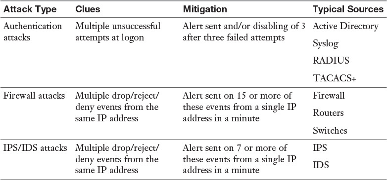
Advanced Configuration of Routers, Switches, and Other Network Devices
When configuring routers, switches, and other network devices, there are some specific advanced configurations that should be a part of securing the devices and the networks they support. The following sections discuss some of these and the security concerns they address.
Transport Security
While encryption protocols such as SSL and TLS provide protection to application layer protocols such as HTTP, they offer no protection to the information contained in the transport or network layers of a packet. Protecting the protocols that work in the network layer and all layers above the network layer can be provided by using Internet Protocol Security (IPsec).
IPsec is a suite of protocols that establishes a secure channel between two devices. For more information on IPsec, see Chapter 1.
Trunking Security
Trunk links are links between switches and between routers and switches that carry the traffic of multiple VLANs. Normally when a hacker is trying to capture traffic with a protocol analyzer, she is confined to capturing only unicast data on the same switch port to which she is attached and only broadcasting and multicasting data from the same VLAN to which her port is a member. However, if a hacker is able to create a trunk link with one of your switches, she can now capture traffic in all VLANs on the trunk link. In most cases, it is difficult for her to do so, but on Cisco switches, it is possible for the hacker to take advantage of the operations of a protocol called Dynamic Trunking Protocol (DTP) to create a trunk link quite easily.
DTP allows two switches to form a trunk link automatically, based on their settings. A switch port can be configured with the following possible settings:
![]() Trunk (hard-coded to be a trunk)
Trunk (hard-coded to be a trunk)
![]() Access (hard-coded to be an access port)
Access (hard-coded to be an access port)
![]() Dynamic desirable (in which case the port is willing to form a trunk and will actively attempt to form a trunk)
Dynamic desirable (in which case the port is willing to form a trunk and will actively attempt to form a trunk)
![]() Dynamic auto (in which case the port is willing to form a trunk but will not initiate the process)
Dynamic auto (in which case the port is willing to form a trunk but will not initiate the process)
If your switch port is set to either dynamic desirable or dynamic auto, it would be easy for a hacker to connect a switch to that port, set his port to dynamic desirable, and thereby form a trunk. This attack, called switch spoofing, is shown in Figure 3-30. All switch ports should be hard-coded to trunk or access, and DTP should not be used.
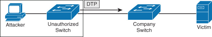
You can use the following command set to hard-code a port on a Cisco router as a trunk port:
Switch(config)#interface FastEthernet 0/1
Switch(config-if)#switchport mode trunk
To hard-code a port as an access port that will never become a trunk port, thus making it impervious to a switch spoofing attack, you use this command set:
Switch(config)#interface FastEthernet 0/1
Switch(config-if)#switchport mode access
Tags are used on trunk links to identify the VLAN to which each frame belongs. Another type of attack to trunk ports is called VLAN hopping. It can be accomplished using a process called double tagging. In this attack, the hacker creates a packet with two tags. The first tag is stripped off by the trunk port of the first switch it encounters, but the second tag remains, allowing the frame to hop to another VLAN. This process is shown in Figure 3-31. In this example, the native VLAN number between the Company A and Company B switches has been changed from the default of 1 to 10.
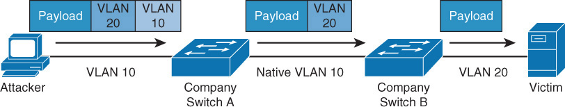
To prevent this, you do the following:
![]() Specify the native VLAN (the default VLAN, or VLAN 1) as an unused VLAN ID for all trunk ports by specifying a different VLAN number for the native VLAN. Make sure it matches on both ends of each link. To change the native VLAN from 1 to 99, execute this command on the trunk interface:
Specify the native VLAN (the default VLAN, or VLAN 1) as an unused VLAN ID for all trunk ports by specifying a different VLAN number for the native VLAN. Make sure it matches on both ends of each link. To change the native VLAN from 1 to 99, execute this command on the trunk interface:
switch(config-if)#switchport trunk native vlan 99
![]() Move all access ports out of VLAN 1. You can do this by using the interface-range command for every port on a 12-port switch as follows:
Move all access ports out of VLAN 1. You can do this by using the interface-range command for every port on a 12-port switch as follows:
switch(config)#interface-range FastEthernet 0/1 – 12
switch(config-if)#switchport access vlan 61
This example places the access ports in VLAN 61.
![]() Place unused ports in an unused VLAN. Use the same command you used to place all ports in a new native VLAN and specify the VLAN number.
Place unused ports in an unused VLAN. Use the same command you used to place all ports in a new native VLAN and specify the VLAN number.
Route Protection
Most networks today use dynamic routing protocols to keep the routing tables of the routers up to date. Just as it is possible for a hacker to introduce a switch to capture all VLAN traffic, she can also introduce a router in an attempt to collect routing table information and, in some cases, edit routing information to route traffic in a manner that facilitates her attacks.
Routing protocols provide a way to configure the routes to authenticate with one another before exchanging routing information. In most cases, you can configure either a simple password between the routes or use MD5 authentication. You should always use MD5 authentication when possible as it encrypts the exchanges between the routers, while simple password authentication does not. Here’s how you could configure this between a router named A and one named B using the Open Shortest Path First (OSPF) routing protocol by using an MD5 key 1 and use the password MYPASS:
A(config)#interface fastEthernet 0/0
A(config-if)#ip ospf message-digest-key 1 md5 MYPASS
A(config-if)#ip ospf authentication message-digest
B(config)#interface fastEthernet 0/0
B(config-if)#ip ospf message-digest-key 1 md5 MYPASS
B(config-if)#ip ospf authentication message-digest
You enter these commands on the interfaces, and you need to make sure the two values are the same on both ends of the connection.
After that, you tell OSPF to use MD5 authentication on the OSPF routing process as follows, entering the commands on both routers:
A(config)#router ospf 1
A(config-router)#area 0 authentication message-digest
B(config)#router ospf 1
B(config-router)#area 0 authentication message-digest
Security Zones
When designing a network, it is advisable to create security zones separated by subnetting, ACLs, firewall rules, and other tools of isolation. The following sections discuss some commonly used security zones and measures to take to protect and shape the flow of data between security zones.
Data-Flow Enforcement
Data-flow enforcement can refer to controlling data flows within an application, and it can also refer to controlling information flows within and between networks. Both concepts are important to understand and address correctly.
It is critical that developers ensure that applications handle data in a safe manner. This applies to both the confidentiality and integrity of data. The system architecture of an application should be designed to provide the following services:
![]() Boundary control services: These services are responsible for placing various components in security zones and maintaining boundary control between them. Generally this is accomplished by indicating components and services as trusted or not trusted. For example, memory space insulated from other running processes in a multiprocessing system is part of a protection boundary.
Boundary control services: These services are responsible for placing various components in security zones and maintaining boundary control between them. Generally this is accomplished by indicating components and services as trusted or not trusted. For example, memory space insulated from other running processes in a multiprocessing system is part of a protection boundary.
![]() Access control services: Various methods of access control can be deployed. An appropriate method should be deployed to control access to sensitive material and to give users the access they need to do their jobs.
Access control services: Various methods of access control can be deployed. An appropriate method should be deployed to control access to sensitive material and to give users the access they need to do their jobs.
![]() Integrity services: Integrity implies that data has not been changed. When integrity services are present, they ensure that data moving through the operating system or application can be verified to not have been damaged or corrupted in the transfer.
Integrity services: Integrity implies that data has not been changed. When integrity services are present, they ensure that data moving through the operating system or application can be verified to not have been damaged or corrupted in the transfer.
![]() Cryptography services: If the system is capable of scrambling or encrypting information in transit, it is said to provide cryptography services. In some cases, this is not natively provided by a system, and if it is desired, it must be provided in some other fashion. But if the capability is present, it is valuable, especially in instances where systems are distributed and talk across the network.
Cryptography services: If the system is capable of scrambling or encrypting information in transit, it is said to provide cryptography services. In some cases, this is not natively provided by a system, and if it is desired, it must be provided in some other fashion. But if the capability is present, it is valuable, especially in instances where systems are distributed and talk across the network.
![]() Auditing and monitoring services: If a system has a method of tracking the activities of the users and of the operations of the system processes, it is said to provide auditing and monitoring services. Although our focus here is on security, the value of this service goes beyond security as it also allows for monitoring what the system is actually doing.
Auditing and monitoring services: If a system has a method of tracking the activities of the users and of the operations of the system processes, it is said to provide auditing and monitoring services. Although our focus here is on security, the value of this service goes beyond security as it also allows for monitoring what the system is actually doing.
Data-flow enforcement can also refer to controlling data within and between networks. A few examples of flow control restrictions include:
![]() Preventing information from being transmitted in the clear to the Internet
Preventing information from being transmitted in the clear to the Internet
![]() Blocking outside traffic that claims to be from within the organization
Blocking outside traffic that claims to be from within the organization
![]() Preventing the passing of any web requests to the Internet that are not from the internal web proxy
Preventing the passing of any web requests to the Internet that are not from the internal web proxy
DMZ
One of the most common implementations of a security zone is a DMZ, such as the Internet and an internal network. (See more information on DMZs earlier in this chapter.) The advantages and disadvantages of using a DMZ are listed in Table 3-16.
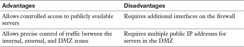
Separation of Critical Assets
Of course, the entire purpose of creating security zones such as DMZs is to separate sensitive assets from those that require less protection. Because the goals of security and of performance/ease of use are typically mutually exclusive, not all networks should have the same levels of security.
The proper location of information assets may require a variety of segregated networks. While DMZs are often used to make assets publicly available, extranets are used to make data available to a smaller set of the public, such as a partner organization. An extranet is a network logically separate from the intranet, the Internet, and the DMZ (if both exist in the design) where resources that will be accessed from the outside world are made available. Access may be granted to customers, business partners, and the public in general. All traffic between this network and the intranet should be closely monitored and securely controlled. Nothing of a sensitive nature should be placed in the extranet.
Network Access Control
Network access control (NAC) is a service that goes beyond authentication of the user and includes an examination of the state of the computer the user is introducing to the network when making a remote access or VPN connection to the network.
The Cisco world calls these services Network Admission Control, and the Microsoft world calls them Network Access Protection. Regardless of the term used, the goals of the features are the same: to examine all devices requesting network access for malware, missing security updates, and any other security issues the devices could potentially introduce to the network.
The steps that occur in Microsoft NAP are shown in Figure 3-32. The health state of the device requesting access is collected and sent to the Network Policy Server (NPS), where the state is compared to requirements. If requirements are met, access is granted.
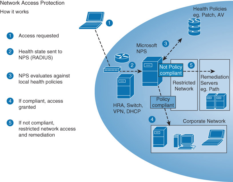
These are the limitations of using NAC or NAP:
![]() They work well for company-managed computers but less so for guests.
They work well for company-managed computers but less so for guests.
![]() They tend to react only to known threats and not new threats.
They tend to react only to known threats and not new threats.
![]() The return on investment is still unproven.
The return on investment is still unproven.
![]() Some implementations involve confusing configuration.
Some implementations involve confusing configuration.
Quarantine/Remediation
If you examine step 5 in the process shown in Figure 3-32, you see that a device that fails examination is placed in a restricted network until it can be remediated. A remediation server addresses the problems discovered on the device. It may remove the malware, install missing operating system updates, or update virus definitions. Once the remediation process is complete, the device is granted full access to the network.
Operational and Consumer Network-Enabled Devices
Beyond the typical infrastructure devices, such as routers, switches, and firewalls, security professionals also have to manage and protect specialized devices that have evolved into IP devices. The networking of systems that in past were managed out of band from the IP network continues to grow. The following sections cover some of the systems that have been merged with the IP network.
Building Automation Systems
The networking of facility systems has enhanced the ability to automate the management of systems including:
![]() Lighting
Lighting
![]() HVAC
HVAC
![]() Water systems
Water systems
![]() Security alarms
Security alarms
Bringing together the management of these seemingly disparate systems allows for the orchestration of their interaction in ways never possible before. When industry leaders discuss the “Internet of things,” the success of building automation is often used as a real example of where connecting other devices such as cars and street signs to the network can lead. These systems usually can pay for themselves in the long run by managing the entire ecosystem more efficiently in real time in a way a human could never do. If a wireless version of this system is deployed, keep the following issues in mind:
![]() Interference issues: Construction materials may prevent using wireless everywhere.
Interference issues: Construction materials may prevent using wireless everywhere.
![]() Security: Use encryption, separate the Building Automation Systems (BAS) network from the IT network, and prevent routing between the networks.
Security: Use encryption, separate the Building Automation Systems (BAS) network from the IT network, and prevent routing between the networks.
![]() Power: When PoE cannot provide power to controllers and sensors, ensure that battery life supports a reasonable lifetime and that procedures are created to maintain batteries.
Power: When PoE cannot provide power to controllers and sensors, ensure that battery life supports a reasonable lifetime and that procedures are created to maintain batteries.
IP Video
IP video systems provide a good example of the benefits of networking applications. These systems can be used for both surveillance of a facility and for facilitating collaboration. An example of the layout of an IP surveillance system is shown in Figure 3-33.
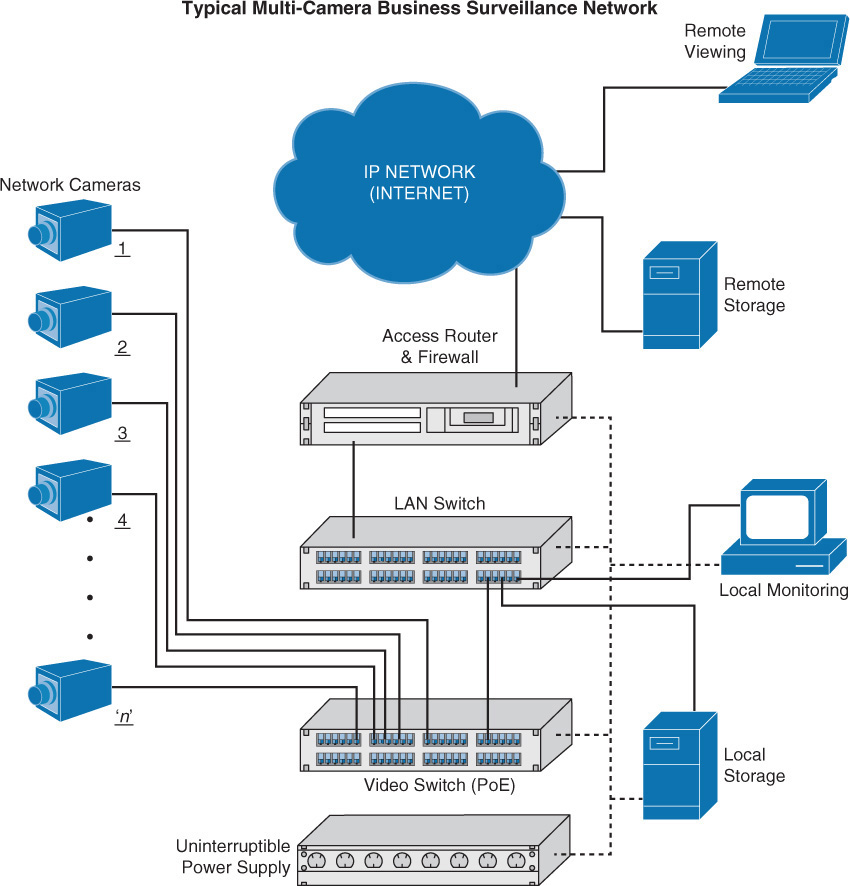
IP video has also ushered in a new age of remote collaboration. It has saved a great deal of money on travel expenses while at the same time making more efficient use of time.
Issues to consider and plan for when implementing IP video systems are:
![]() Expect a large increase in the need for bandwidth.
Expect a large increase in the need for bandwidth.
![]() QoS will need to be configured to ensure performance.
QoS will need to be configured to ensure performance.
![]() Storage will need to be provisioned for the camera recordings.
Storage will need to be provisioned for the camera recordings.
![]() The initial cost may be high.
The initial cost may be high.
HVAC Controllers
One of the best examples of the marriage of IP networks and a system that formerly operated in a silo is heating, ventilation, and air conditioning (HVAC) systems. HVAC systems usually use a protocol called Building Automation and Control Network (BACnet). This is an application, network, and media access (MAC) layer communications service. It can operate over a number of layer 2 protocols, including Ethernet.
To use the BACnet protocol in an IP world, BACnet/IP (B/IP) was developed. The BACnet standard makes exclusive use of MAC addresses for all data links, including Ethernet. To support IP, IP addresses are needed. BACnet/IP, Annex J defines an equivalent MAC address composed of a 4-byte IP address followed by a 2-byte UDP port number. A range of 16 UDP port numbers has been registered as hexadecimal BAC0 through BACF.
While putting these systems on an IP network makes them more manageable, it has become apparent that these networks should be separate from the internal network. In the infamous Target breach, hackers broke into the network of a company that managed the company’s HVAC systems. The intruders leveraged the trust and network access granted to them by Target and then from these internal systems broke into the point-of-sale systems and stole credit and debit card numbers, as well as other personal customer information.
Sensors
Sensors are designed to gather information of some sort and make it available to a larger system, such as an HVAC controller. Sensors and their role in SCADA systems are covered in the section “Critical Infrastructure/Supervisory Control and Data Acquisition (SCADA)/Industrial Control Systems (ICS),” later in this chapter.
Physical Access Control Systems
Physical access control systems are any systems used to allow or deny physical access to the facility. They can include:
![]() Mantrap: This is a series of two doors with a small room between them. The user is authenticated at the first door and then allowed into the room. At that point, additional verification occurs (such as a guard visually identifying the person) and then the person is allowed through the second door. Mantraps are typically used only in very high-security situations. They can help prevent tailgating. A mantrap design is shown in Figure 3-34.
Mantrap: This is a series of two doors with a small room between them. The user is authenticated at the first door and then allowed into the room. At that point, additional verification occurs (such as a guard visually identifying the person) and then the person is allowed through the second door. Mantraps are typically used only in very high-security situations. They can help prevent tailgating. A mantrap design is shown in Figure 3-34.
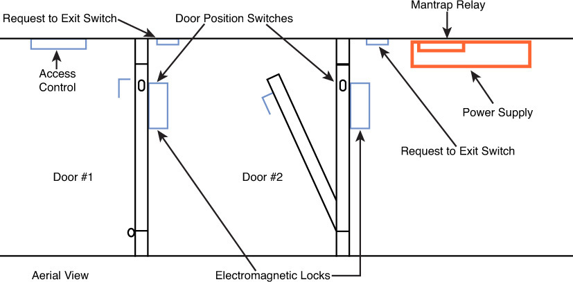
![]() Proximity readers: These readers are door controls that read a card from a short distance and are used to control access to sensitive rooms. These devices can also provide a log of all entries and exits.
Proximity readers: These readers are door controls that read a card from a short distance and are used to control access to sensitive rooms. These devices can also provide a log of all entries and exits.
![]() IP-based access control and video systems: When using these systems, a network traffic baseline for each system should be developed so that unusual traffic can be detected.
IP-based access control and video systems: When using these systems, a network traffic baseline for each system should be developed so that unusual traffic can be detected.
Some higher-level facilities are starting to incorporate biometrics as well, especially in high-security environments where there are terrorist concerns.
A/V Systems
Audio/visual (A/V) systems can be completely connected to IP networks, providing the video conferencing capabilities discussed earlier. But they also operate in other areas as well. Real-time IP production technology integrates network technology and high-definition serial digital interface (HD-SDI), the standard for HD video transmission. This is the technology used to support live video productions, such as sportscasts.
Securing these systems involves the same hardening procedures you should exercise everywhere, including:
![]() Changing all default passwords
Changing all default passwords
![]() Applying best password security practices
Applying best password security practices
![]() Enabling encryption for the video teleconference (VTC) sessions
Enabling encryption for the video teleconference (VTC) sessions
![]() Disabling insecure IP services (such as Telnet and HTTP)
Disabling insecure IP services (such as Telnet and HTTP)
![]() Regularly updating firmware and applying patches
Regularly updating firmware and applying patches
![]() When remote access is absolutely required, instituting strict access controls (such as router access control lists and firewall rules) to limit privileged access to administrators only
When remote access is absolutely required, instituting strict access controls (such as router access control lists and firewall rules) to limit privileged access to administrators only
Moreover, some measures that apply specifically to these systems are:
![]() Disabling broadcast streaming
Disabling broadcast streaming
![]() Disabling the far-end camera control feature (used to adjust a camera remotely)
Disabling the far-end camera control feature (used to adjust a camera remotely)
![]() Performing initial VTC settings locally, using the craft port (a direct physical connection to a device) or the menu on the system
Performing initial VTC settings locally, using the craft port (a direct physical connection to a device) or the menu on the system
![]() Practicing good physical security (such as restricting access, turning off the device, and covering the camera lens when not in use)
Practicing good physical security (such as restricting access, turning off the device, and covering the camera lens when not in use)
![]() Disabling any auto answering feature
Disabling any auto answering feature
![]() Disabling wireless capabilities when possible
Disabling wireless capabilities when possible
![]() Logically separating VTCs from the rest of the IP network by using VLANs
Logically separating VTCs from the rest of the IP network by using VLANs
Scientific/Industrial Equipment
Both scientific and industrial equipment have been moved to IP networks. In hospitals, more and more devices are now IP enabled. While this has provided many benefits, adding biomedical devices to a converged network can pose significant risks, such as viruses, worms, or other malware, which can severely impact overall network security and availability. It is essential to have a way to safely connect biomedical, guest, and IT devices to the IP network. You should isolate and protect specific biomedical devices from other hosts on the IP network to protect them from malware and provide the appropriate quality of service.
Critical Infrastructure/Supervisory Control and Data Acquisition (SCADA)/Industrial Control Systems (ICS)
Industrial control systems (ICS) is a general term that encompasses several types of control systems used in industrial production. The most widespread is Supervisory Control and Data Acquisition (SCADA). SCADA is a system operating with coded signals over communication channels so as to provide control of remote equipment. It includes the following components:
![]() Sensors: Sensors typically have digital or analog I/O and are not in a form that can be easily communicated over long distances.
Sensors: Sensors typically have digital or analog I/O and are not in a form that can be easily communicated over long distances.
![]() Remote terminal units (RTUs): RTUs connect to the sensors and convert sensor data to digital data, including telemetry hardware.
Remote terminal units (RTUs): RTUs connect to the sensors and convert sensor data to digital data, including telemetry hardware.
![]() Programmable logic controllers (PLCs): PLCs connect to the sensors and convert sensor data to digital data; they do not include telemetry hardware.
Programmable logic controllers (PLCs): PLCs connect to the sensors and convert sensor data to digital data; they do not include telemetry hardware.
![]() Telemetry system: Such a system connects RTUs and PLCs to control centers and the enterprise.
Telemetry system: Such a system connects RTUs and PLCs to control centers and the enterprise.
![]() Human interface: Such an interface presents data to the operator.
Human interface: Such an interface presents data to the operator.
These systems should be securely segregated from other networks. The Stuxnet virus hit the SCADA used for the control and monitoring of industrial processes. SCADA components are considered privileged targets for cyberattacks. By using cybertools, it is possible to destroy an industrial process. This was the idea used on the attack on the nuclear plant in Natanz in order to interfere with the Iranian nuclear program.
Considering the criticality of the systems, physical access to SCADA-based systems must be strictly controlled. Systems that integrate IT security with physical access controls like badging systems and video surveillance should be deployed. In addition, the solution should be integrated with existing information security tools such as log management and IPS/IDS. A helpful publication by the National Standards and Technology Institute (NIST), Special publication 800-82, provides recommendations on ICS security. Issues with these emerging systems include:
![]() Required changes to the system may void the warranty.
Required changes to the system may void the warranty.
![]() Products may be rushed to market with security an afterthought.
Products may be rushed to market with security an afterthought.
![]() The return on investment may take decades.
The return on investment may take decades.
![]() There is insufficient regulation regarding these systems.
There is insufficient regulation regarding these systems.
Exam Preparation Tasks
You have a couple of choices for exam preparation: the exercises here and the exam simulation questions on the CD-ROM.
Review All Key Topics
Review the most important topics in this chapter, noted with the Key Topics icon in the outer margin of the page. Table 3-17 lists these key topics and the page number on which each is found.
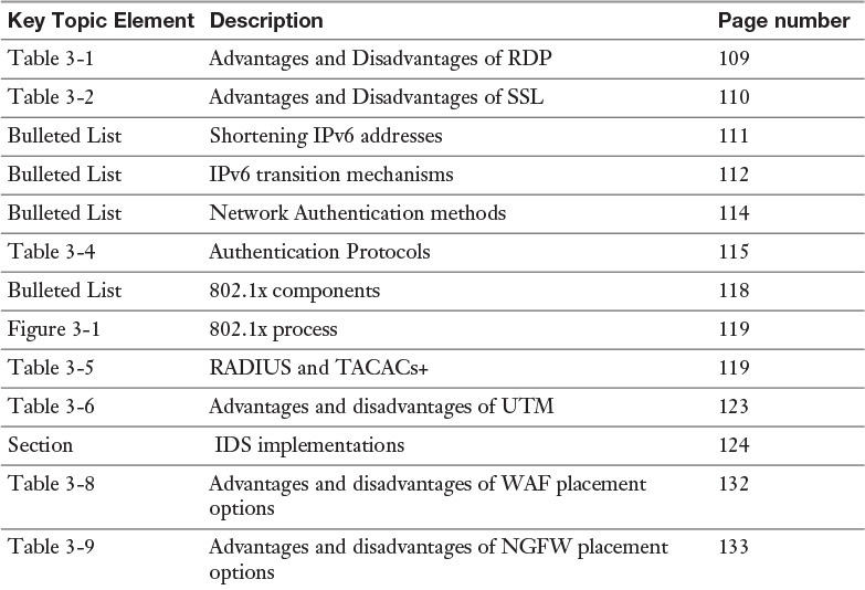
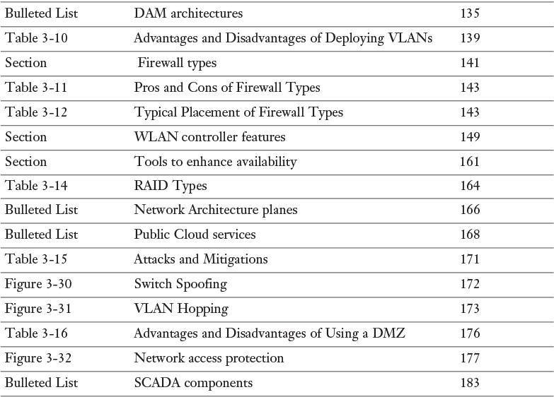
Define Key Terms
Define the following key terms from this chapter and check your answers in the glossary:
Virtual Network Computing (VNC)
Generic Routing Encapsulation (GRE)
Hypertext Transfer Protocol Secure (HTTPS)
Password Authentication Protocol (PAP)
Challenge Handshake Authentication Protocol (CHAP)
Extensible Authentication Protocol (EAP)
unified threat management (UTM)
in-line network encryptor (INE)
security information and event management (SIEM)
hardware security module (HSM)
web application firewall (WAF)
next-generation firewall (NGFW)
database activity monitor (DAM)
virtual local area network (VLAN)
mean time between failures (MTBF)
Redundant Array of Inexpensive/Independent Disks (RAID)
Infrastructure as a Service (IaaS)
network intrusion detection system (NIDS)
statistical anomaly-based detection
stateful protocol analysis detection
network intrusion prevention system (NIPS)
Internet Protocol Security (IPsec)
BACnet (Building Automation and Control Network)
Review Questions
1. Which of the following is not a command-line utility?
a. RDP
b. Telnet
c. SSH
d. NAT
2. Which of the following is not a valid IPv6 address?
a. 2001:0db8:85a3:0000:0000:8a2e:0370:7334
b. 2001:0db8:85a3:0:0:8a2e:0370:7334
c. 2001:0db8:85a3::8a2e:0370:7334
d. 2001::85a3:8a2e::7334
3. Which IPv4-to-IPv6 transition mechanisms assigns addresses and creates host-to-host tunnels for unicast IPv6 traffic when IPv6 hosts are located behind IPv4 network address translators?
a. GRE tunnels
b. 6 to 4
c. dual stack
d. Teredo
4. What port number does HTTPS use?
a. 80
b. 443
c. 23
d. 69
5. Which of the following is not a single protocol but a framework for port-based access control?
a. PAP
b. CHAP
c. EAP
d. RDP
6. Which of the following is not a component of 802.1x authentication?
a. supplicant
b. authenticator
c. authentication server
d. KDC
7. Which IDS type analyzes traffic and compares it to attack or state patterns that reside within the IDS database?
a. signature-based IDS
b. protocol anomaly-based IDS
c. rule- or heuristic-based IDS
d. traffic anomaly-based IDS
8. Which of the following applies rule sets to an HTTP conversation?
a. HSM
b. WAF
c. SIEM
d. NIPS
9. Which DAM architecture uses a sensor attached to the database and continually polls the system to collect the SQL statements as they are being performed?
a. interception-based model
b. log-based model
c. memory-based model
d. signature-based model
10. Your organization’s network has recently started experiencing performance issues. After researching the problem, you discover that collisions have increased over the past couple months at an alarming rate. You need to implement a solution to eliminate the collisions. What should you do?
a. Replace all routers with hubs.
b. Replace all hubs with switches.
c. Replace all firewalls with routers.
d. Replace all IPS with IDS.