Chapter 3
Tracking
In this chapter we will start working with Blender. This is a very important chapter and one of the most difficult ones to master. To learn how to track a shot perfectly might require an entire book and much time practicing. It’s hard to fit all the techniques about tracking in one chapter, but we will cover the basics and some tips.
Basics of Tracking
For people who are not familiar with this term, I would define this technique as the reconstruction of a real scene into a CG scene by re-creating the movement of a physical camera and transferring the information of each movement into keyframes in a 3D world. This is a very interesting and powerful tool for these kinds of visual effects projects. It allows us to integrate real environments and elements into our project so we can do many tricks later on with them.
Previously we had to use external programs for tracking because Blender didn’t have this feature, but the Blender Foundation added this functionality into their software. This opens a new world of possibilities and options into this wonderful software, as we no longer need to use any external software for these kinds of jobs, and it provides very nice and tight integration.

Preparing the Footage
Let’s consider a couple of suggestions before we start working with the tracking system.
The most important one is to remember to have at least eight elements to track in our footage. Sometimes some of these elements get occluded or just don’t track well enough so we need to make sure we will have at least eight elements to track all the time later on.
Another important thing is to get as much information about what we use in the real scene so we can transfer all this information into the 3D scene later on. For example, it is very important to know the type of camera we are going to use, the focal length, the sensor size, and some other measurements. For these additional measurements, it would be interesting, if possible, to measure the distances between key elements so we can tell Blender the exact distances between the tracking points. Then, we can re-create the scene in a much more accurate way.
In the previous chapter I mentioned parallax. This is one of the keys to a good tracking solution. Parallax is used to explain the different distances we perceive when we see objects. If we place the marks to be tracked on the same area and distance from the camera, the result is not going to be good enough for some projects so we need to provide additional information to the tracker by placing some elements at different distances to provide the depth information to the tracking solver to re-create the scene. In the example scene, we placed some stands next to the character without occluding the area we are going to use later on. However, by doing this, we provide more elements to track and we make sure we are going to have a good parallax for the tracking solver.
Finally I would suggest the use of contrasted elements. This means using elements that are easy to perceive by the tracker and trying to avoid similar colors between the elements to track and the background; otherwise, it will be very easy for the tracker to lose the tracked element.
NOTE: In the example for this book, I intentionally prepared the footage in a simple way and far from the very best conditions. This helps to show some of the common problems in some productions and to shows how to solve these problems. It is likely that sometimes you could be working with footage that contains such problematic elements.
Working with the Tracker
Time to do some tracking in Blender. First thing we need to do is set up the scene units in Blender. We can select the unit type we want to use by going to the Scene button and clicking on the Metric button. This will help us later on to get the right values when we work with 3D elements.

Now let’s go to the tracking panel. Click on the Editor Type button and select Movie Clip Editor. The interface will change into the tracking interface.


Click on the Open button and select the footage you are going to use. Usually Blender works better with image sequences for this kind of task and JPEG format is faster than others (e.g., PNG) but the quality is not as good, so sometimes you need to think what would be best for your project.
We can click on the Prefetch button to load all the frames into the memory RAM. That way, instead of reading the frames from the hard drive, which is quite slow, it will read the frames from the RAM, speeding up the playback and the tracking as well. We can also click on the Set Scene Frames button, and Blender will automatically set the start and end frame in our project based on the length of the footage we loaded.
We can also build a proxy (lower-quality) version of our original footage to work much faster and then switch to the original footage when we want higher quality. To do this, we can go to the right-side panel in the Proxy section, select the options you want to generate the proxy version, and click on the Build Proxy button. It will take a little while to generate the proxy, but this will allow us to work much faster in the long run.

We can swap the footage from the original to the proxy one by clicking on the Proxy render size button.
Now we can play the footage with the combination Alt+A. If you want to just use a portion of your footage, you can easily set up the start and end for your footage by pressing the S key for the starting position and the E key for the ending position.
Calibration inside Blender
Recall in the previous chapter when we prepared the calibration sheet. Now we are going to use the lens distortion information we collected, thanks to the calibration sheet we prepared previously.
Once we have our footage loaded and before we start tracking the marks, we should go to the Display section and click on Grid. We should then see something like this:

These lines should match the ones from our footage when we had the calibration sheet in front of the camera. It’s quite possible that the lines on your footage are not completely straight as these ones, so to adjust these lines we have to adjust the values in the Lens section where it says K1, K2, and K3.
Once we have the values that make the lines in Blender match the footage, we should see the grid distorted as in this example:

Now we can notice how much the lens we used in our footage distorted the light rays when these ones hit our sensor. The reason for doing this procedure is that the render engines usually cannot simulate the lens distortion from a real camera in our viewport and also doesn’t know how much distortion to apply so we are building this information to use it later on during our pipeline.
Once we have the right distortion values, we should create an undistorted proxy or video with the previously mentioned proxy panel so we can use the undistorted footage in our 3D viewport and we can align our 3D geometry in the right way. For the moment we can disable the grid in the display section and continue with our tracking.
Placing the Marks
It’s time to place the tracking marks. To do this, we just need to press the Ctrl (control) key and click on any area we want to track and we will notice that a new element shows up in the viewport:

This is a tracking point and it’s defined by two main areas: the pattern area and the search area. The pattern area is the area that the tracker is going to try to find in the previous or next frames of your footage.
Then we have the search area, which is used by the tracker to define an area in which to look for the pattern area in other frames. To turn on the search area in the viewport, go to the right panel in the Marker Display section and click on the Search button.
This is very important because sometimes you want to define an area to search to avoid undesired results. It also makes the calculations much faster as the tracker doesn’t need to find the pattern area in the entire frame but just in the limited area we chose as the search area.
Smaller search areas are faster to calculate than bigger ones. It might not sound important, but if you need to track several elements during many frames and with some high-quality footage, you may need to keep this in mind. Continue placing trackers for the rest of the frames. You can use the timeline to choose a better place to use the trackers.

We can use the same shortcuts that are used with other elements in Blender, so we can use G to grab a tracking point, S to scale, R to rotate, and A to select all the tracking points; press A again to deselect. Once we finish placing all the marks we need, we can select one or more tracking marks, and in the left-side panel we can find the Track section:

With this panel we can start tracking the markers we have already placed on the entire footage. We can track a marker forward until it stops or backward until it stops, but also we can track frame by frame in both directions for finer control. This panel also allows us to clear portions of tracking data for the marks based on the actual frame.

A common problem with the tracking is that sometimes the reference pattern area is lost for apparently no reason, but there’s actually a reason: the accuracy we try to get with that particular mark. By default the accuracy correlation is set to 0.750, but sometimes we need to drop it a little bit so we can continue using that particular tracker. To do this, we need to go to the Tracking Settings section on the right-side panel.
The most important parameter here is the correlation. As stated previously, it’s set to 0.750 by default, but we can adjust this parameter to get more precise tracking in our marker by increasing this setting up to 1 or less precise by decreasing to 0. Don’t drop this value too much as it will produce a less accurate solution. Usually a little bit lower than the default is fine.
If our tracking point is still failing, we should try to move the point a little bit or change the size of the pattern area or the search area a little bit. There’s no magic setting for that, but sometimes it’s necessary to tweak these settings and retrack the marker until it completes the entire range of frames we want. The Motion model and the Match options are also very critical to get the right tracking. Try Affine and Previous frame, respectively, in case you run into problems. These are usually the most precise settings.
Solving the Tracking
We should have now a good number of accurate tracking points, so we can proceed to the camera solving process. In this stage Blender is going to collect all the information about our tracking marks and is going to calculate how the distances between the tracking marks are performing in the real-life footage and will provide a simulated version of the real camera movement so we can apply it to our 3D camera.
First we need to tell Blender how to calculate the distance and the movement of these points, so we need to go to the right-side panel and fill as much information as we can on the Camera section:

If you are not sure about these settings, you can use the Camera Presets button or look for the specifications of your camera in the camera’s manual or on the Internet. It’s important to fill the parameters correctly so that our simulation will be more accurate.
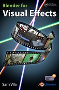
At the other side of the viewport, we need now to go to the Solve section. In this section there are very interesting settings that will help us get a good result.
We need to define a range of frames with enough movement to provide the best information to the calculation. Here we return to the concept of parallax. That is why it was so important to define previously, because now is its critical moment. We need to look through our footage to find a range of frames with enough parallax and movement to get as much information as Blender needs to generate the 3D camera.
There’s no standard value for this, so you need to find in your footage a good starting frame and end frame, and then type the values of these frames in the boxes Keyframe A for the starting frame and Keyframe B for the ending frame. We can also check the Keyframe option if we want Blender to calculate this for us.
Finally we click on the Solve Camera Motion button, and Blender will start the calculation process. It will take a little while to complete the job. We won’t see many things happening after that, because it does the work internally. The most important thing to keep an eye on is this value:

Solve error reveals the accuracy of the calculations generated based on our settings. A value above 1.0 means that the solution calculated is not as accurate as it should be, so we would have some problems during the next stages; we don’t want that, so try to avoid going higher than 1.0. A value lower than 1.0 should be good enough for what we need, while a value much higher than 1.0 would be totally unacceptable.
If we still have values above 1.0, then we need to tweak a few things and recalculate the camera movement in the Solve panel.

The most common problem is having a tracking point that is not accurate enough. To check this, we can go back to the right-side panel in the Track section and we should see at the bottom an Average Error part. It works very similarly to the previous setting.
If it is above 1.0, the tracking point is not sufficiently accurate; however, it’s less critical than the overall solved camera calculation, so we could use values above 1.0 if we still have some other tracking points with good values. We could use tracking points with values up to 2.0 more or less, but we should avoid use tracking points with a value near 3.0 or higher.
We should check all our track points one by one to make sure we only use the most accurate ones in the calculation on the Solve panel. If you notice some tracking points with high values, you should delete or disable the problematic ones.

There is also an interesting option on the left toolbar called Clean up, which highlights the markers with the values we want to delete. This will help us to find the wrong markers instead of checking them manually one by one.
Another way to increase the precision of our camera solution is with the Refine section on the Solve panel:

There are different options for a particular problem in this menu. Blender autocorrects some values, but this may affect the accuracy of the original parameters we provided, so make sure the values provided by this feature are what you are looking for.
Applying the Solved Camera
Let’s return to the 3D viewport. I suggest that you split the view, as we will still work a little bit more with the tracking interface and we will need the 3D viewport as well.

Now that we are on the 3D viewport, let’s change to the camera view by pressing 0 on the numeric keypad. Then, in the tracking interface, click on the Set as Background on the Scene Setup section in the left panel.
We should see now how our footage is shown through the 3D camera in Blender; however, we don’t have any motion in that camera yet, so we need to apply the tracking solution to the 3D camera. To do this, we need to select the camera and go to the Object constraints button and then click on Add Object Constraint and select Camera Solver:

If we play back our animation now in the 3D viewport, we would notice that something is happening now with the camera, and we can even see the tracking points working as they should. However, the axis or the scale might be wrong, so we need to set up these things to make sure we are on the right track for the next stage.
Go back to the tracking interface and click on the bottom menu in the Reconstruction option.
In this menu we will set up the axis and the main size of the scene. Let’s start with the origin of our scene. To do this, we just need to select one of our tracking marks and then click Set Origin in the Reconstruction menu. We should notice how the 3D viewport has changed.
Next we define the floor. For this one, we need three tracking marks that remain on the same axis in the real footage and that are as close as possible to the real floor; then we click on Set Floor.
We do the same with the wall if necessary. We can further tweak the scene with the other options in the Reconstruction menu to set the X and Y axes if we need.
The last parameter we need to define is the actual distance between two real points. That’s why it was important to collect as much information as we could during the shooting of the footage so we can apply this information to these options. Let’s define the scale by selecting two tracking marks between which we know the distance and clicking on Set Scale. We can now define the size on the left-side panel under the Set Scale section.
Now we should have something quite close to the original footage but in our 3D scene. We could add some 3D geometry and play with it, but maybe we would need to tweak manually the origin point in the 3D viewport until it matches the perspective and the size of the objects we want. There are no formulas here—just move a little bit the origin point until what you see in the viewport makes sense to you. Usually it’s quite fast to fix small issues with the perspective just by moving the origin point a little bit.
As a final note in this process, I would suggest dropping some 3D elements in some areas we are going to use to see if those objects perform well during the entire sequence. If the result is not convincing, keep tweaking the origin point in the 3D viewport until you are happy with the result. Then we can proceed with the next stage: scene setup.
Plane Track
This is a different technique that we won’t use in the example for this book, but I will explain it because it can be very useful for other projects. Basically a plane track allows us to place or replace an element in a particular dimensional plane. For example, we could replace an advertisement banner from a shop in our footage or we could replace a cell phone screen—anything that remains in the same dimensional plane.
The good thing about using this tracker is that we are not forced to adjust our tracking marks to match the plane we want to use. As long as the tracking marks are on the same dimensional plane, we can always adjust our plane track in the position we need.
Let’s see an example:

We need four tracking marks so we can apply the plane track. They don’t have to be in the position we need as long as these marks stay on the same dimensional plane—in this case, the wall.
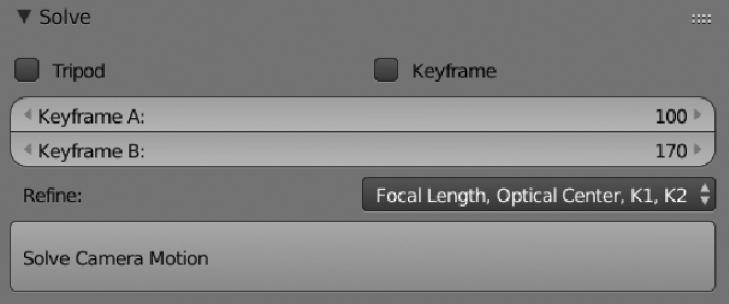
Once we have our four marks tracked, we can go to the Plane Track section on our Solve panel on the left side of the screen and click on Create Plane Track.
Now we should see something like this:

That’s our plane track at its default position.
We can adjust the corners in the way we need manually:

Notice that now we can play back our footage and the plane should match our footage perfectly.
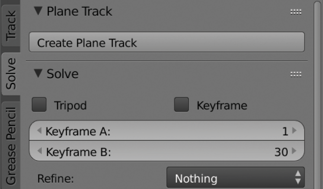
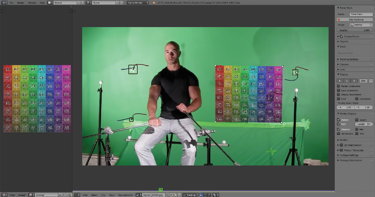
On the right panel we can find some interesting options as well:

By clicking on the Auto Keyframe button, we can manually adjust the corners of our plane track in case we have some problem. Another interesting option is the Image field. To use it, we need to load an image in the Image Editor.
If we select the image we loaded in the Image Editor in Plane Track settings, we can preview on the viewport any image we want:
This is mainly for preview purposes. We will see later on how to use this data in a final composition.

Summary
This chapter is a bit technical, and for some people it might be challenging at the beginning. But tracking is a very nice tool to know, and it’s worth the effort to learn how to do it in the right way so we can expand our toolset and be more creative in our productions. It’s important to keep in mind that it’s hard to get a perfect track when you are just beginning to learn this technique. It requires practice and experience, so my final suggestion is to keep working on tracking shots even if they are simple tests or something basic just to gain experience and get used to these options. When I did my first tracking, I did many things wrong and the results were far from being good, but today I’m using this technique almost every day so it’s no longer a problem. Keep trying hard with the tracking tools until you have mastered them; 3D tracking is a really sweet feature, too.