Chapter 7
Compositing
It’s time to get into the most important chapter of this book, the final one. This chapter is divided into two main parts: explanation of the compositing nodes and compositing the robot scene. It is divided in this way so you can have a clear idea of how to use the nodes in your own projects but also to show you a real example of how to create a composition. During this process, we will see some tips as well of how to achieve interesting effects thanks to the compositor in Blender.

First Steps
Let’s jump into the compositor by selecting the Node Editor in the Editor Type button. Then we should click on the third icon at the bottom bar called Compositing nodes and check Use Nodes and Backdrop so we can start working with the nodes. The backdrop option allows us to see the result on the viewport once we add an Output Viewer node from the Add menu at the bottom.
The concept around these nodes is to connect some of these nodes between an input and an output. As input we can select an image, scene, video, or other file, and then we can output the result to a specific file/format or to the Compositor node. In between these connections, we can add many other nodes to tweak the image as we wish.
Nodes Overview
Blender has multiple nodes for compositing our scene. It is really important to know how each of these nodes works so we can take advantage of these utilities to create the scene in the way we want. Here is a quick overview of all the available nodes and how to use them.
Inputs
These are the first things we need in our composition. We can have multiple inputs and join them together in very different ways before we output the result.
For inputs we can use still images, image sequences, videos, masks, textures, and more.
The following sections describe the different types of inputs.
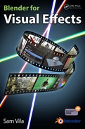
Render Layers
This input provides information from a rendered 3D scene and can include several passes.
Image
With this input we can select a file from the hard drive to be included in the composition. This file can be a single file, a sequence of images, or a movie file.
Texture
This brings a texture from the actual scene into the compositor.
Value
With the Value node we can create a global numeric value to share with other nodes.
RGB
Similar to the previous one, the RGB node generates a color value instead of a numeric value.
Time
This node is useful for animating parameters over time, even though this input was used more often in previous versions due to the lack of having keyframes in the nodes as the recent Blender versions have.
Movie Clip
This node is similar to the Image node, but it allows you to load a movie clip from, for example, the tracking or masking editors.
Bokeh Image
This node should be used in conjunction with Bokeh Blur or a similar node. It generates an image to simulate camera lens effects.
Mask
This node loads a mask layer created from the mask editor to be applied into the composition. We can use this node to affect selected areas in our composition.
Track Position
So we don’t have to manually tweak the position of our elements, this node provides translation information from a tracking point to the composition; it is used in conjunction with tracking data.
Outputs

These nodes provide the final output in our composition and can be of use for previsualization purposes on the viewport.
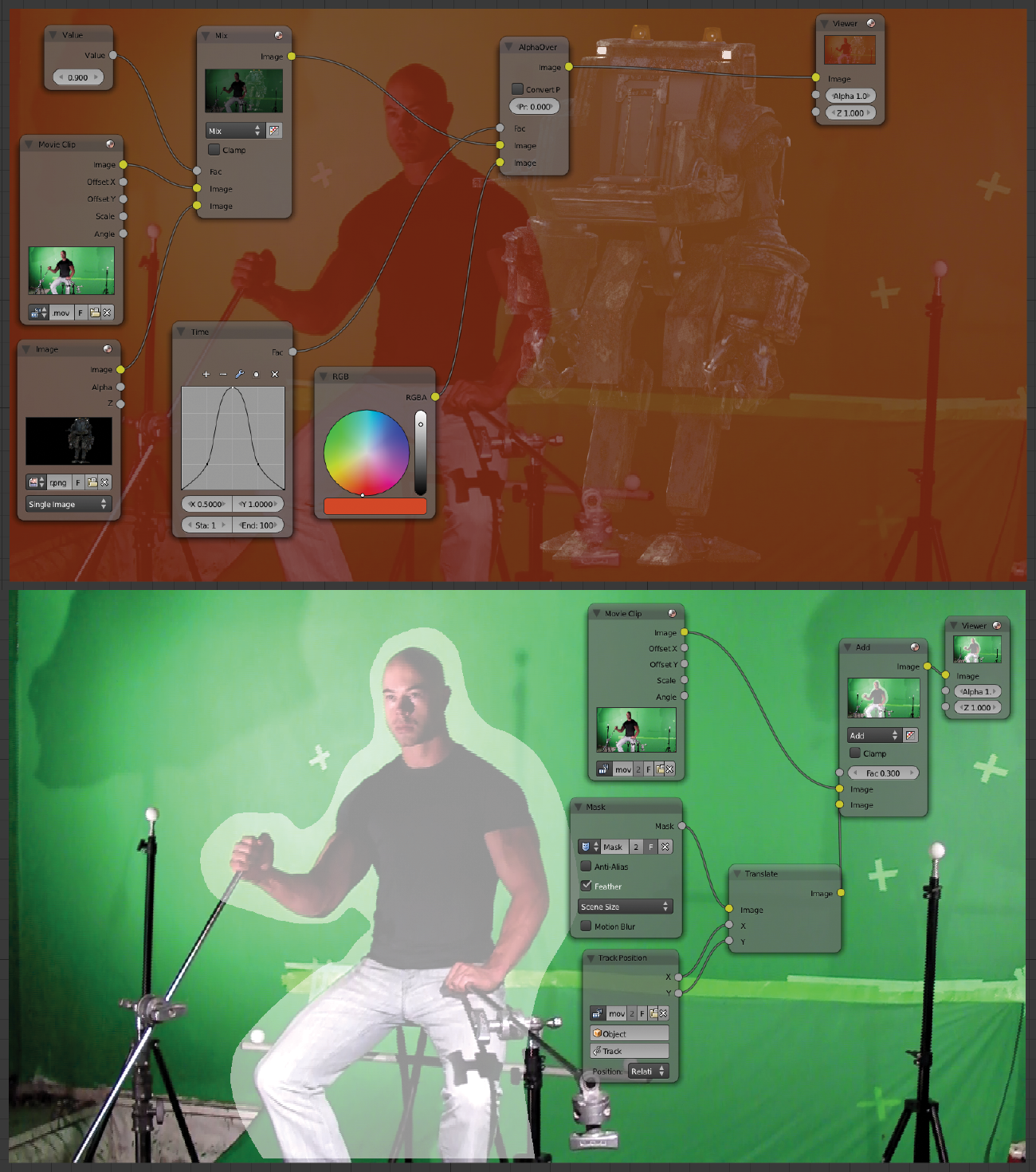
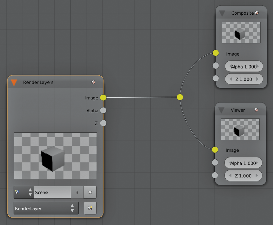
Composite
This node brings the result from the last node connected to the final output. Usually we will use this node if there’s only a single output that is predefined in the Render Panel in the 3D viewport.
Viewer
This is a very useful node to preview the actual stage of our composition. By attaching this node into any other one, we would see the result at that particular point. We can use the shortcut Ctrl+Shift+left mouse button to rapidly connect this node into the selected one.
Split Viewer
Another previsualization node, this node has two inputs so we can connect two different nodes and see on the viewport half of one and half of the other one. We can control the regions with the slider.
File Output
Similar to the Composite node, this node provides multiple outputs instead of having a single output of the result. By adding several of these nodes, we can customize our output formats in different ways. We can select different output settings, paths, and formats. This is very useful if we need to save several passes in different folders.
Levels
This node is used to adjust the levels in a 1D format. It has one input and two outputs: Mean or Standard Deviation, depending on how we want to apply our color correction.
Layout
These nodes are used mainly for organization purposes. We can arrange our compositor nodes in the way it makes more sense for us while keeping a clean workspace. We would need these nodes in complex compositions so we can have a clear idea of what we are doing without getting lost in all those nodes.
Frame

We can use a frame with our nodes so we can grab the entire frame and move all the nodes inside without having to move them individually. We can also assign colors and labels to the frame so we can arrange our composition in a better way. To remove nodes from the frame, you can press Alt+P to unparent the nodes from the frame and return them back to normal.
Reroute
This very simple node utility is also very useful; it provides rerouting functionality so we can split or change the direction of the connections between nodes.
Switch

With this node we can swap connections from one node to another just by clicking in the check box.
It is useful to see different setups in a very quick way without having to plug Viewer nodes to specific nodes, which is good for comparisons.
Group

The group node is a very interesting tool to collect our nodes into a group, so that we can organize our composition much better.
Hitting the Tab key, we can enter or exit the selected group. If we arrange our composition with some of these groups, we can make our life much easier by just having control over a few group nodes instead of several separated nodes. We can create inputs and outputs inside the group node by just dragging a connection into one of the borders of the group, and once we are out of the group we can still have access to these connections as with a regular node.
Check the right-side panel for additional options.
Distort
With these nodes we can manipulate an image or an input in many ways. We can change basic values such as position, scale, and rotation but also create some other more complex effects.
Translate

Basically we can change the position of our inputs with this node, in the X and Y coordinates.
Rotate

This node controls the rotation of an input. We can select three different filter modes, Bicubic, Bilinear, and Nearest, to choose how the pixels are calculated into the resulting output.
Scale

Similar to the previous ones, this node instead controls the scale of an input. We can select how to apply the scale factor in four different ways: Render Size, Scene Size, Absolute, and Relative.
Flip

Simply use the flip node to invert the direction of an input; it can be applied in X and Y individually or in both axes at once.
Crop
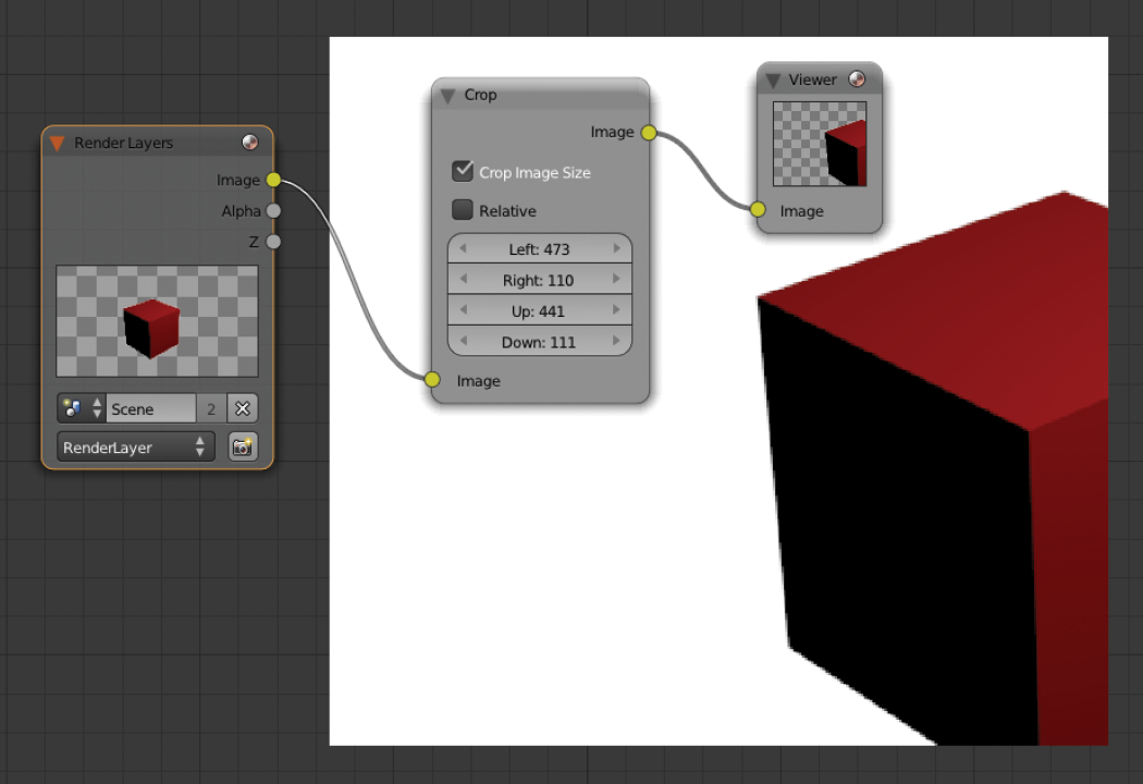
This node provides a cropping function for an input. We can define the new margins with this node by adjusting exactly how many pixels we want to crop from each side of the image.
Transform

This node is a combination of the nodes Translate, Rotate, and Scale, but in a single node. If we need to apply more than one of these nodes to our input, we can use the Transform node.
Displace

This very interesting node creates a deformation for an input based on another input, so we can control the amount of displacement we want in each axis. This could be useful, for example, to simulate heat distortion in our footage and other artistic distortion effects.
Lens Distortion
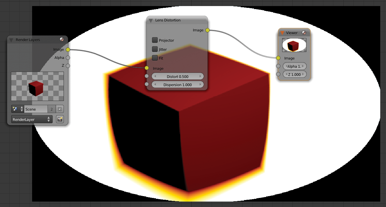
With this node, you can create a lens distortion effect. Sometimes this is nice to apply in our compositions if we want to simulate a real camera distortion effect, as all cameras have this particularity to some degree. We can control the amount and type of distortion and the dispersion to apply to our image.
Map UV
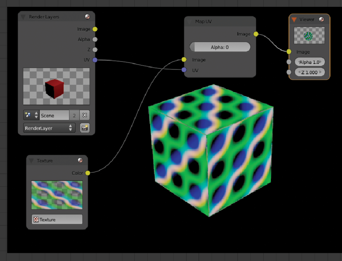
This is a very powerful node. It provides the ability to retexture an element without having to rerender the entire scene. There are two inputs: one for the texture we want to apply and a UV input to overwrite the look of our element with the new texture.
Keep in mind that we need to have the element we want to change unwrapped correctly or else we could get undesired results.
Stabilize 2D
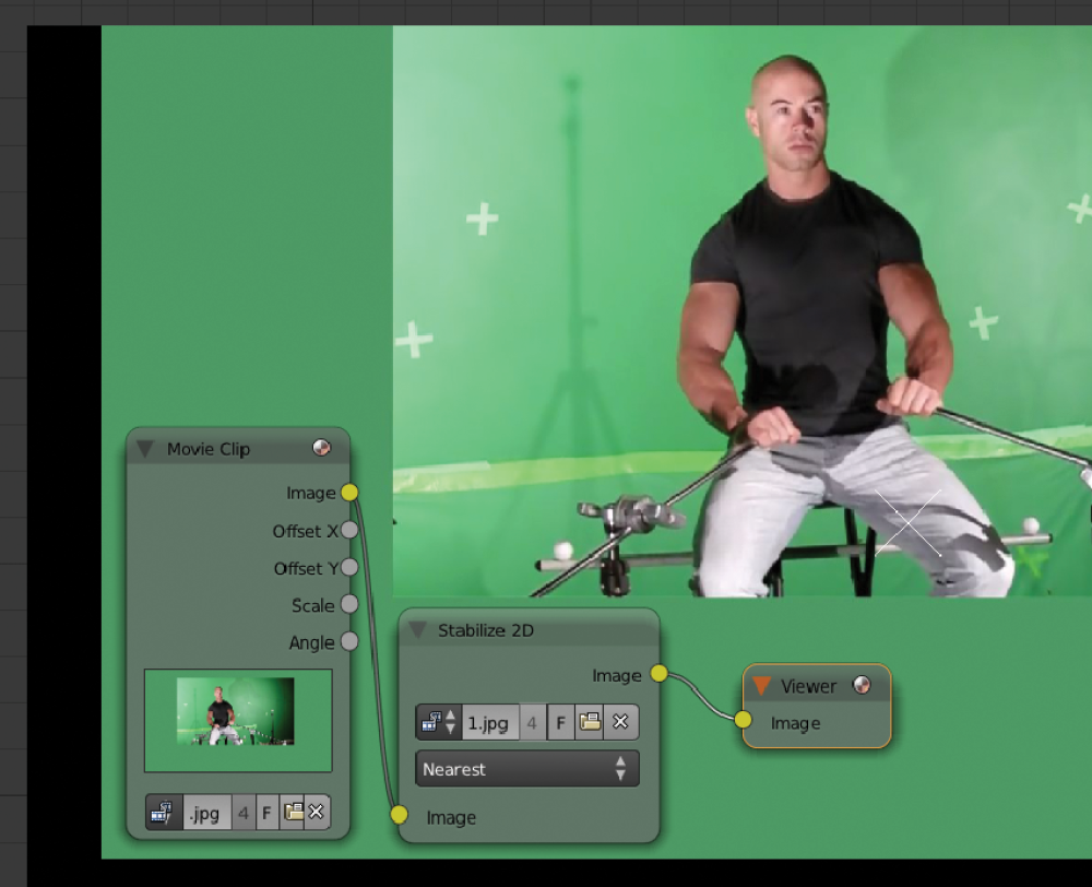
Using a tracking point from the tracking panel, this node provides stabilization to our footage. We can use just one tracking point for a 2D stabilization so we don’t need to calculate a full tracking in the 3D scene if we just want to stabilize our footage.
We can also have more than one point in case we want to stabilize the rotation and the zoom factor in our footage. We can assign the points we want the Stabilize 2D node to use in the right-side panel of the Movie Clip Editor:

Movie Distortion

We will use this node most of the time when we want to integrate 3D elements into original footage. As we saw in the overscan description in Chapter 5, most cameras produce distortion. With this node we can apply the same distortion from our tracked footage into our 3D renders. That way, it will match the lens distortion and the composition will be more accurate.
In Chapter 5 we explained how to render with overscan to compensate for the fact that once we apply this node in our composition, it might reduce the dimensions of our 3D plates. By having that extra buffer we can apply the Distortion node without a problem because we should have enough pixels even if our plates get distorted and reduced.
Plane Track Deform

This node mainly works with a planar tracking setup. As we saw in Chapter 3 in the “Plane Track” section, we used an image to preview our planar tracking. Now, with this node, we can do a composition using that tracking data. We can assign any image to our track plane, and it will also generate an alpha channel using the Plane output so we can combine our track plane with any background we want.
If there is any overlap between our track plane and another element in our composition, we would add a mask on top so the track plane will look like it is behind that element.
Corner Pin

This tool is similar to the one we can find in other design programs. Basically, it allows us to distort an image by adjusting individually the corners of the image. The node has four inputs, and we can set each value by clicking on top of the drop box area. We can use the output setting Plane to generate a matte to combine with another image as a background.
If this node is not very intuitive for you because it uses numerical inputs, we can always plug in a Normal node to control the corners in a more visual way:

Matte
This category includes a group of nodes to control the masking and the keying of footage. There are several green screen solutions in this section.
Difference Key
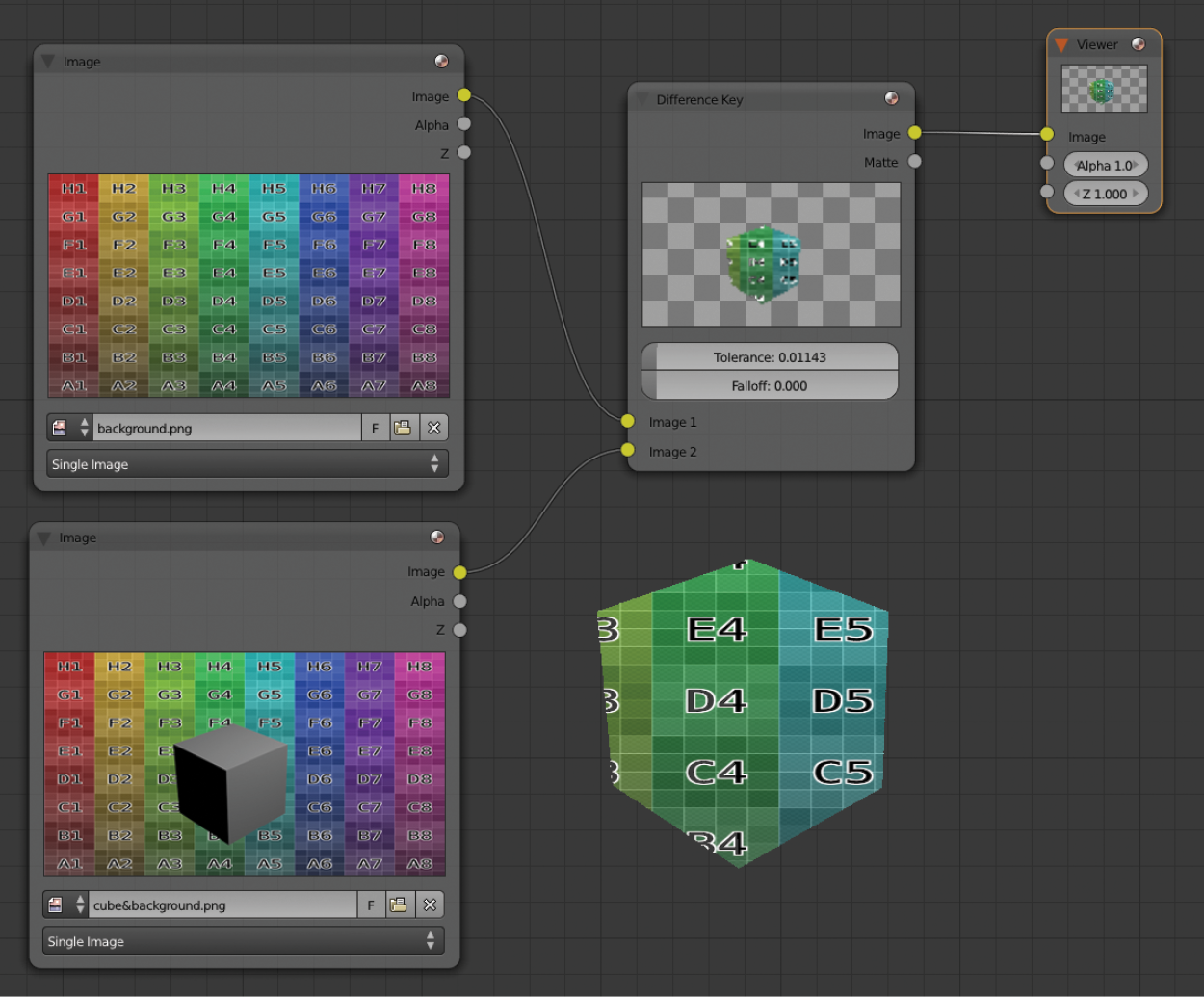
This creates a mask based on the difference of pixels from two inputs. All the pixels that are the same on both images turn transparent in the output. It also allows us to use the Matte output if we want to apply this mask onto a different image.
Color Spill

Usually when you are working on a green screen removal, you still have some spilling from the green screen background into the main element. This node decreases the amount of spill in our composition by adjusting individual color channels.
Distance Key, Chroma Key, Color Key, and Channel Key

These nodes are very similar to each other. They all do chroma keying based on a key color and provide different settings to control the quality of the chroma key. However, these nodes are quite old and not as powerful as the next node we are going to see.
Keying
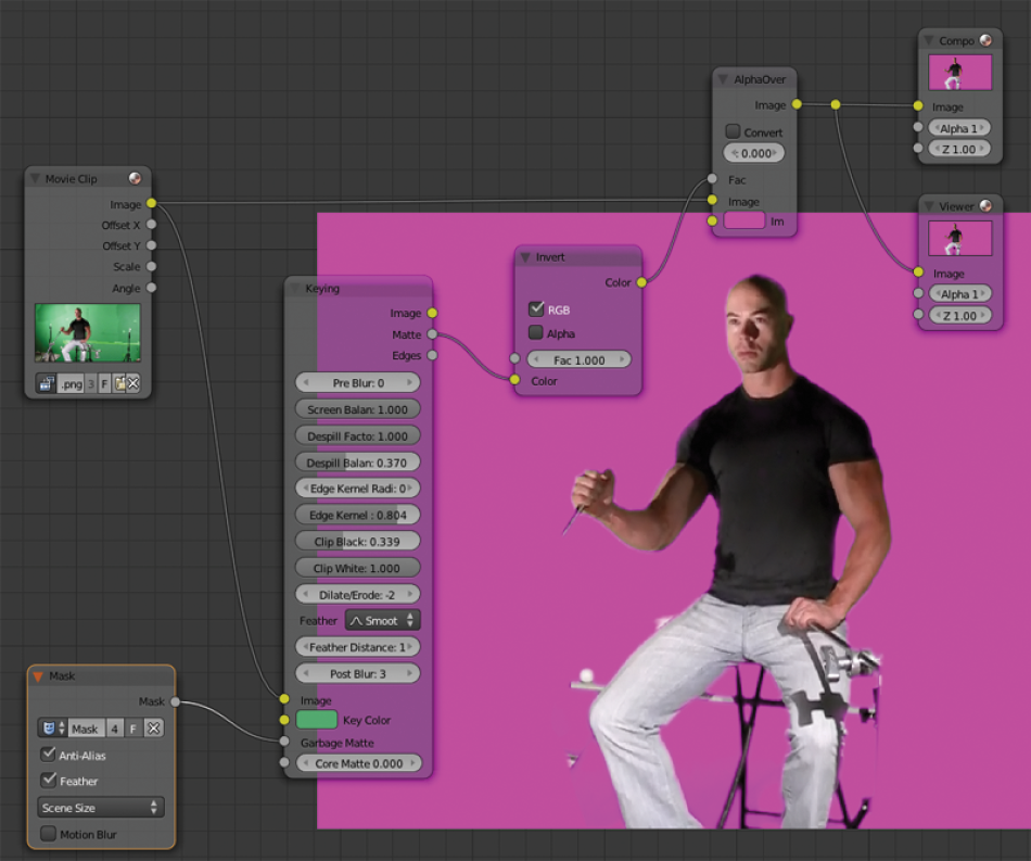
This node is a replacement for the ones we just presented. It provides more control, more quality, and more options in just one node. It also provides more control over the connected masks.
Luminance Key

With this node, we can create a mask just in the brightest areas from the input. It allows us to control the highest value and the lowest value that define the areas we want to use as a mask.
Double Edge Mask

This node creates a transition between two input masks. This is very useful for advanced masking as we can create nice gradient masks to have better control over the areas we want to mask in our final composition.
Keying Screen

This node outputs color information based on a tracking mark. This can be useful, for example, to cover tracking marks with a similar color. As we can see in the example, we get two plain colors from two trackers.
Box Mask and Ellipse Mask

Based on the settings we want to use, this node creates a box mask or an elliptical mask. These nodes can also work in combination with other masks and provide different ways to combine them with the Mask Type setting.
Converter
These nodes are related to how we want to handle the channels. We can change, swap, or do other combinations with the channels as well as some other utilities to work with alpha channels.
Combine and Separate (RGBA, HSVA, YUVA, YCbCr)

Basically, these nodes allow us to work individually with the color channels and rebuild them if we need them to work in a different way. Usually the most standard color workflow is RGBA, but if our project needs some other color workflow, we can reconnect the channels with these nodes in the way we need.
Alpha Convert

This node converts a premultiply alpha channel into an alpha key or vice versa. A premultiply alpha is a channel that is already multiplied with the RGB channels, and an alpha key channel is an independent channel with no RGB channels by multiplying the resulting alpha.
We can select how we want to work with the alpha channels in the render panel under the Shading section if we work with the Blender Internal render engine or in the Film section if we use Cycles as the render engine.
Math

This node allows us to control the inputs in a particular way and can be used to mix or subtract inputs or control the amount of individual inputs. It is especially useful for working with alpha channels.
Here’s an example of how to combine two alpha channels into one:

ID Mask

With this powerful node, we can isolate objects in our 3D scene so we can adjust them separately without affecting other parts of the scene. We can set an index for each object by the Object Panel in the Relations section (Pass Index). We can assign the same ID to more than one object if we want to adjust all the objects on the same ID at once, or we can create as many IDs as we need.

Set Alpha
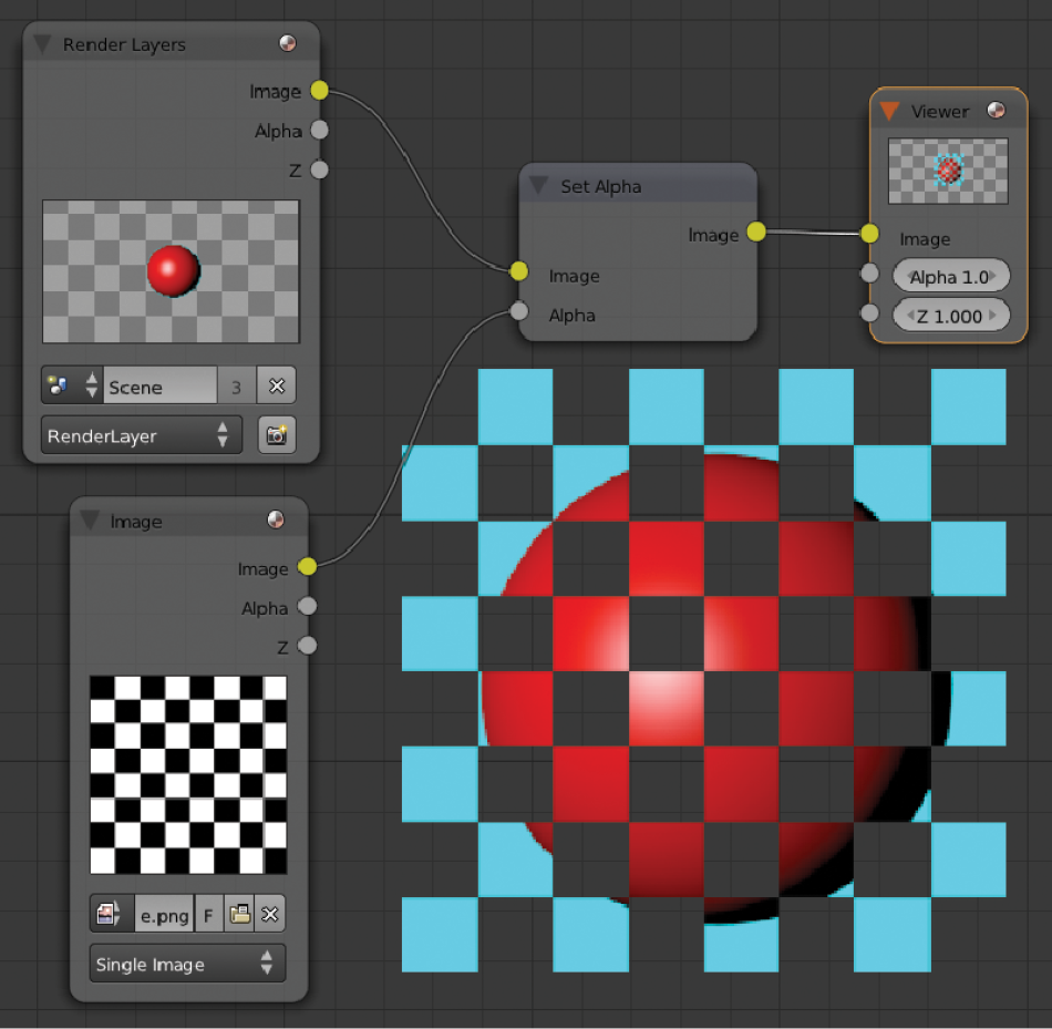
We use this simple node to set an alpha channel from another image, which is quite straightforward.
RGB to BW

This node converts a color input (RGB) into a black-and-white (BW) output.
ColorRamp

With this interesting node, we can generate a color ramp to be mixed with an input so that we can control the values of our inputs. The image above is just an example with a color channel, but this node is especially useful for controlling the depth channels with a setup like this:

As you can see, this node is very useful for a wide range of operations.
Filter
Blender has a collection of filters to enhance our images, some blur nodes, and some others related to lens effects.
Filter

This node provides different results for our input image. It’s like a group of artistic nodes, all in one single node. Maybe the most commonly used are Sharpen and Soften, but the use for these nodes depends very much on the result we want to obtain.
Blur

With this basic blur node, we can define how much blur we want in our input node, and we can choose between several blur methods to get the exact result we want.
Directional Blur

A very nice and useful blur node, this one in particular allows us to choose an angle and a distance of the blur we want. Not only that, we can also create very interesting effects by using the Spin and Zoom options.
Bilateral Blur

This node allows us to blur an input while preserving the edges and some detail on the borders, instead of the overall blur from other blur nodes. This node is very useful to get rid of some noise areas on our render plates by blurring them while preserving some of the detail.
You could use different render passes and combine several render passes as a determinator to keep some of the detail.
Vector Blur

This is a very quick way to generate motion blur in our creations. Once we set up our render to provide a depth channel and a vector channel, we can use these channels to blur only the parts of the scene where there is some kind of motion. This trick works very well if we want to achieve realistic images that show motion. On the other hand, if you are looking for quality you should use real motion blur by setting up the option in the Render Panel:

Dilate/Erode

With this node we can contract or expand an input. It’s especially useful to control the alpha channel in some of our elements or in some keying case where we need to adjust fine details to have perfect background removal or better integration in our scene.
Inpaint
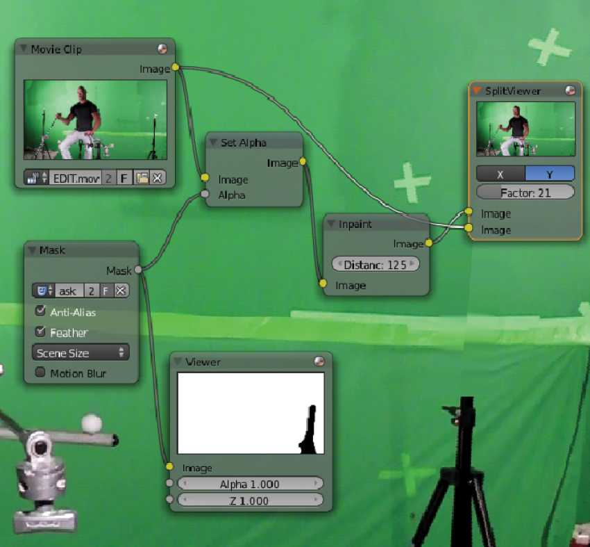
This node is useful to cover automatically some specific areas by reconstructing the selected area with the nearest pixels until it fills that area. We can use this node, for example, in a situation where we need to remove some wire work in a shot or to remove some undesired element. Don’t expect to have a perfect result as it is very complicated to reconstruct areas if we don’t have enough information, but for some situations it can be useful.
It is especially useful for removing tracking marks in a very quick and dirty way.
Despeckle
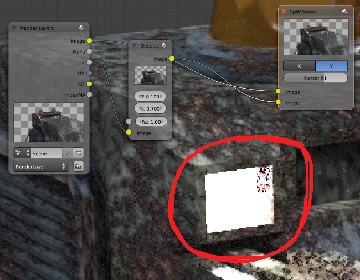
This is a clean-up node for some areas in our renders. If we have some artifacts or some noise in our render, we can try to use this node to clean up some of these problems. Even though it’s always better to have the right plates before we start postproduction, sometimes we can still use some postproduction tools to reduce the render time or to correct some problems.
Defocus

By using a depth channel in conjunction with this node, we can simulate how the real camera works with the depth of field channel. It’s useful to control the depth of field during the postproduction stage, but don’t forget that we can also employ this technique during the rendering as well by using Cycles; the performance is almost the same in render terms.
Also, working with depth channels directly could cause very severe artifacts and damage the quality of our final composition. Later in this chapter we will see how to address this issue and learn some workarounds.
Glare

This amazing node simulates lens flares and other light effects. It has different types of effects such as Simple Stars, Streaks, Fog Glow, and Ghosts. It’s based on the brightest areas of our input. Keep in mind as well that we can mix some of these lens flares together to generate a final lens flare. That way we can achieve incredible results.
Usually we would connect this node to an ID Mask node to isolate the areas where we want to apply our Glare node.
Bokeh Blur

This blur node simulates the type of blur we can have with a real camera. By combining this node with a Bokeh Image input, we can customize how we want the blur to be processed.
Pixelate

Blender usually tries to keep as much quality as possible during scaling operations. In the image above, the first Transform node reduces the image to 10%, and the second Transform node increases the image to the size it was before. As I said, Blender tries to keep as much quality as possible so we won’t notice as much pixelation as we could see in 2D imaging software by doing the same procedure. So, the Pixelate node basically allows us to overwrite Blender’s filtering to avoid pixelation, allowing us to have pixelated images in case we need this for some reason.
Sun Beams

This node is really helpful to fake some volumetric lighting. It basically gets the luminance from an input and applies a fading effect in a particular direction. We can control the direction and the distance. We can also animate this if we need to by using keyframes.
Keep in mind that the generated image will have transparency so you will need to mix it with another image to have the right result.
Vector
These nodes are helpers for other ones, basically to adjust some values or to have some extra control over some particular nodes. In all the cases these nodes are very useful and very powerful. We can achieve very interesting results with them.
Normal

By using this node in a setup like the image above, we can adjust the shading of a particular element in our 2D composition. In other words, we can use this node, for example, to relight an element without having to rerender. If we combine this technique with some others, we can achieve immediate results without having to calculate again the entire scene, just to refine some areas of lighting. A good combination would be to use this method with the Map UV node.
Vector Curves

We can control the values of some channels by using this node, so we can fine tune some of the elements. This usually works in conjunction with other nodes with similar inputs and outputs.
I want to give a brief explanation about what we are going to see now with the next three nodes. They are used mainly to make adjustments in passes that need to be controlled with internal values. For example, if we plug a Viewer node into the Z channel to check the depth pass, we will notice that we cannot really see anything but white. That’s because what we see are the depth values in an unsupported range, so we need to connect some nodes to be able to work with the range we need.
Normalize

This node provides an output of an average value based on the input. This might sound hard to understand but what it basically does is get the highest value and the lowest value and create an average value inside the supported range. It would be perfect for handling depth pass information, but this node actually creates some problems, such as flickering or artifacts, during animation, so I suggest using the nodes we are going to see next to have a better result. Use this node only for a quick preview or to have an idea of which values you might need for the Map Value node and for the Map Range node.
Map Value

This node is similar to the one we just saw except it works using numerical values. It essentially does a similar thing but provides more control over the depth channel information and also more reliable data.
Map Range

This is the node I suggest to use for one big reason: it provides the same quality as the Map Value node but this one uses real distance values so we can adjust these settings in a much more precise way.
To get the distance values, we can use the Distance value in our camera. First click on the Limits option and you will notice a light-yellow cross in the camera’s viewport:

That’s the position of the Distance value in the camera. We can use this value to set up our focal point or just to get some distance values.

All we need to do now is fill the From Min and From Max values in our Map Range node based on the distance that the yellow cross is telling us. You can use the Clamp option to crop some of the high and low values from the depth pass, and you can tweak the actual range with the To Min and To Max fields.
A final consideration about using depth passes in Blender: this software doesn’t deal very well with passes at this stage. It has some severe limitations, one of which is not providing an anti-aliasing filter for the depth pass. This creates a very dirty result:

To solve this problem, we could increase our resolution two or three times just to generate this pass and on top of that we could add a Blur filter set as Gaussian:
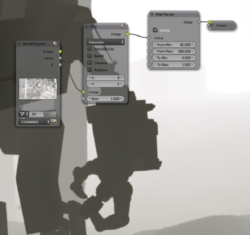
This is not the best way to do composition, but until Blender fixes this problem this could be a valid workaround. Later on we will see other methods to generate nice depth of field passes.
Color
Here we discuss the set of nodes for controlling the colors and the channels as well as some nodes for mixing inputs.
RGB Curves
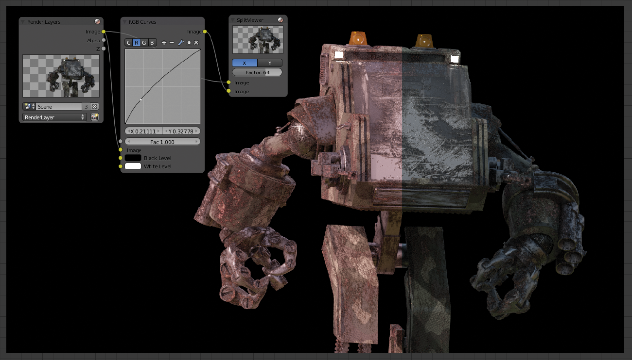
This node is quite standard in almost every 2D or 3D design application. Basically, we can control the brightest and darkest areas of a particular channel to assign a new value by modifying the RGB curve. The bottom-left corner refers to the darkest point, while the upper-right corner is the brightest. The middle part refers to mid tones.
We can adjust the overall image or just the channels we need.
Mix

We are going to use this node most of the time, because it’s very useful and very common. We have many ways to combine our inputs by using this node and all its modes. This node is necessary to recombine all the passes if we are rendering elements with separate layers. That way we can have some extra control over the entire process.
Also we will use this node to combine different elements into a single plate.
Hue Saturation Value

Another standard color utility, this node can be used to change the hue and saturation values, as simple as that.
Bright/Contrast

This brightness and contrast node is the same as in any 2D image retouching software.
Gamma

This node controls the gamma value of an input.
Invert

Basically, you can invert a channel (RGB or alpha) with this node. It can be useful sometimes, especially if you work with some problematic masks that need to be combined in a specific way.
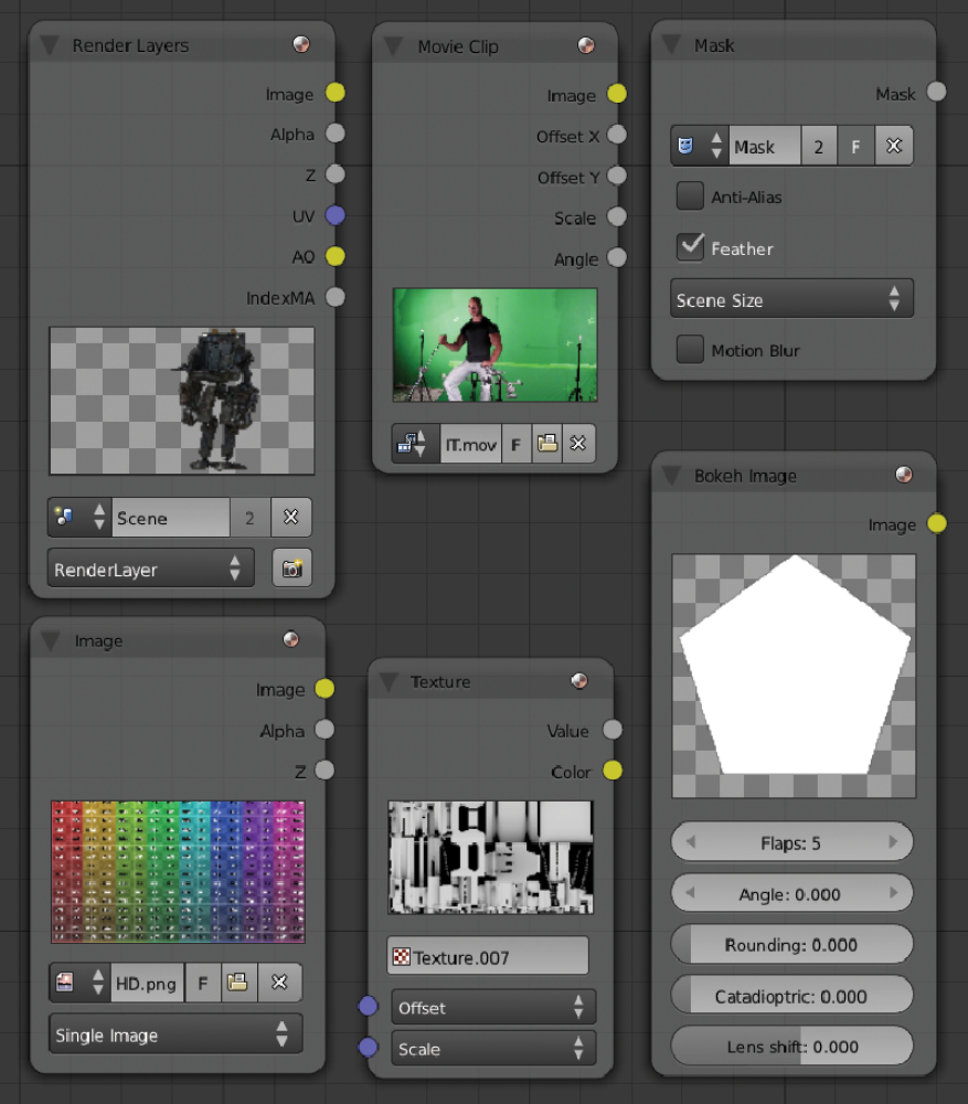
AlphaOver

With this node we can mix two inputs based on an alpha channel, so we can create a basic composition with this node. This node also provides the option to apply the alpha as a key or as a premultiply.
Z Combine
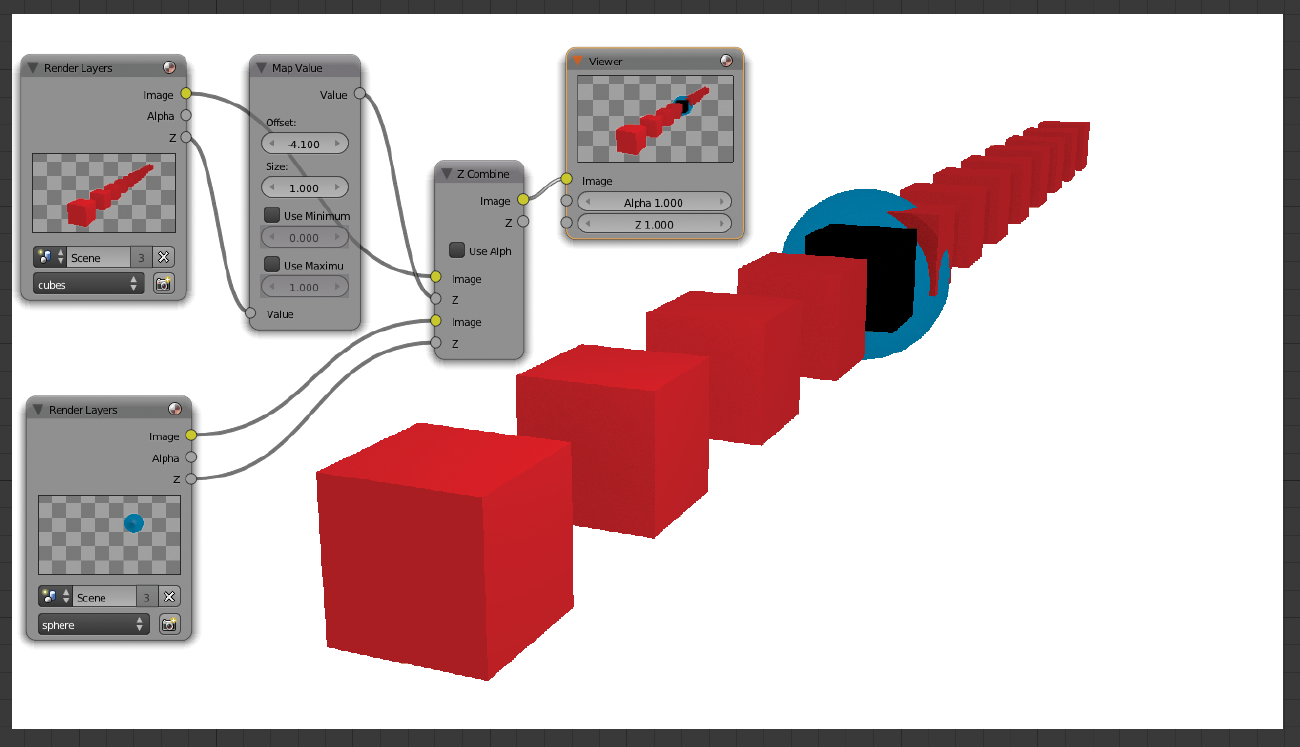
This powerful node creates compositions based on a depth channel. We can create fog or similar atmospheric effects with this node or use it for compositing elements, as in the image above.
Keep in mind the problem with the depth channels I mentioned before. Some workaround explained in this book might be necessary to get a better final image.
Color Balance

With this node for color correction, we can control the Lift, the Gamma, and the Gain. By combining this node with some other color nodes, we can have a lot of control over the look of an element.
Hue Correct

Another color tool for color correction, with this node we can control not only the Hue but the Saturation and the Value (brightness) as well.
Tonemap

This node is basically for adjusting a high dynamic range image (HDR or HDRI). As these formats contain additional information for the lighting, they need to use specific tools to adjust the values. So, with this node we can adjust these values for this image format.
Color Correction

This node is similar to the previous color correction nodes, but in this case it is based on numerical values.
Compositing the Scene
Now that we know how to use all the nodes and what result we get from each individual node, let’s see an example of using a combination of nodes to finish the project. We have been following the project of the robot from previous stages, and it’s time to commit all the previous steps into the final result. We can start to set up the basic elements for the scene. In this case we’re going to use four inputs: the 3D robot element, the actor footage, the glass, and the background. This is a very basic setup to see how all these elements works together:

Even though this is not the final version of our node tree, the idea of this setup is just to block the basic stuff we are going to use later on. First we need to make sure we have everything in place, so we can then tweak individual elements.
We saw before how to prepare the scene to render with different layers. Now it’s time to see how these render layers are plugged together.
Basically, we need to use the layer channels from our input node in a particular way. When we combine the layers in the right way, we can recreate the original render but with the benefit of being able to adjust individual passes without having to render again the frames. This provides a very powerful tool for tweaking the look of our scene or elements in a very detailed way.
This is a diagram of how we should plug the nodes together to recreate the original render:

Where we see the + symbol, we would use a Mix node (from the color section) with a value of Add, which by default is set to Mix. Where we see the × symbol, we would use the same node but instead of Add we would use Multiply.
The previous diagram might be a little bit intimidating at first, but let’s see the same diagram in our example:
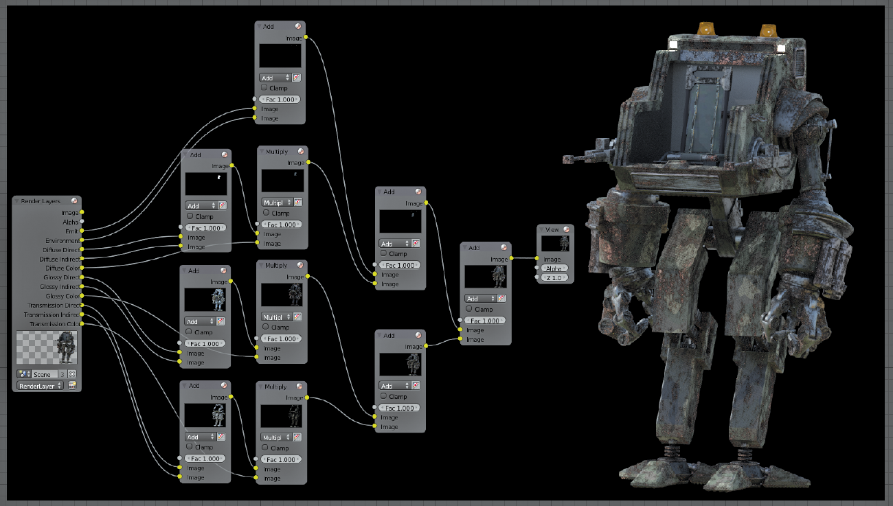
We have in this image the same connections as in the previous diagram. If we did the connections in the right way, we should have the exact image as the original render by using these nodes.
Now we can tweak individual elements with total control over each channel.
At this stage it is very important to be organized or else we might end up having a lot of trouble understanding our complex node tree.
In the previous image we saw that to have a basic setup for one of our elements (the robot) we used ten nodes already, so the total number of nodes could be a problem if we keep adding elements. Let’s use node groups to manage our elements in a much more effective way.
We can select the nodes we want and create a group from individual nodes by pressing Ctrl+G:

As soon as we create our group, we will notice how the background color changes. That shows us that we are inside of our group, and we cannot access other nodes until we exit from this group. To enter and exit a group, all we need to do is hit the Tab key.

Much better now, right? We still have the availability to tweak our nodes when we want, but now we need to deal with just one node for this element.
We can label groups by colors or with custom names using the side panel:
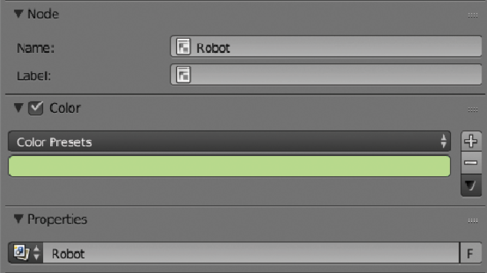

Using colors really helps to organize complex projects.
We should do the previous steps to arrange the elements we need in our composition, and we can use colors for better organization.

Without grouping our nodes, the same composition for this image would look like this:

That’s why we need to start using groups and labels as soon as we can or else we will end up with a big mess. The image above shows the basic nodes needed to put the elements together. This would be the minimum to start working on.
Now that we have all the basic elements together, we could keep adding more and more nodes to have more details until we are happy with the result.

We can add some of these extra details. Let’s start with an example for the lens flares.
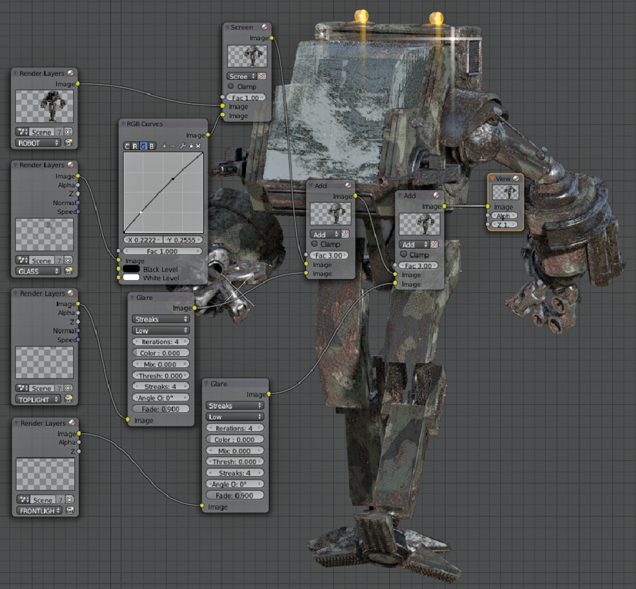
We used two Glare nodes to increase the effect of the light sources for the robot and then mixed them together with the Mix node. We can use the Object ID and the Material ID nodes to read the appropriated channels to tell the Glare node where to apply the effects.
Film Grain
Let’s explore now two different techniques to simulate film grain. This is very important especially if we try to integrate some CG element into some real footage. Usually cameras produce some grain in the image, some cameras more than others. CG images don’t produce any grain. (Don’t confuse the lack of samples during rendering with grain. That type of grain shouldn’t be on our final renders. We should use only clean renders and add the grain later on as we are going to see now.)
If we don’t add grain to our CG elements when we add them in our composition, it will look like something not well integrated into the original footage.
Why are we showing two techniques to produce grain? Well, they are very different: one is a fake grain that works quite nicely and is easy to generate, and the other one generates the grain based on our original footage and so is usually more accurate. Sometimes you cannot use the second technique, so that’s why it is good to know how to add fake grain just in case.
Fake Grain
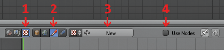
To use this technique, we need to generate some textures to simulate the grain. Let’s click on the texture node icon (1), then on the brush icon (2), click on New (3), and finally click on Use Nodes.
We should see something like this:
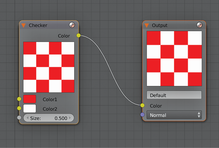
This is the default Checker texture. We can delete this texture so we can add the ones we need.
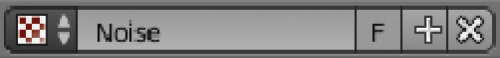
We need to add a noise texture:

Then we duplicate this two times more, and we do the connections in this way:
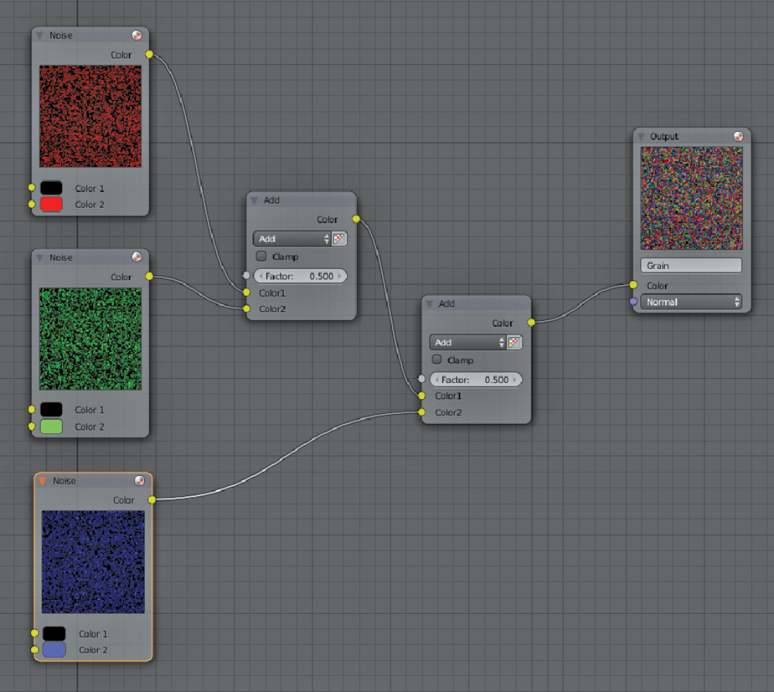
We connect the first two textures with a color mix RGB node set as Add with a Factor of 0.500. We then mix from this (combined) node with the third one. Finally we connect the mix RGB node to the output.
Now let’s add our texture to our composition:

We use a texture node and select the texture we just created. Then we plug our texture node in a filter node, and we select Soften with a very low Factor: 0.05.
After this we plug the Soften node into a Mix node from the color library. We set this node as Color, and for the other input to the CG layer, we want to add the grain. We can then adjust the amount of grain with the factor field in our Mix node. Usually a factor of 0.100 should be fine, but in the image above we raised the factor much more to show the difference clearly.
By the way, don’t forget to click on the fake user icon (F) on the texture node to make sure the textures we created is saved in our project:
Real Grain
It’s time to see how the other method to generate grain works. As I mentioned before, this second method is based on the grain from the original footage. To obtain the grain from footage we have to separate the footage and the grain.
We would need a few seconds of footage where everything remains static, including the lighting. This works best if we can film some seconds of footage with everything static before any action begins in our shot. If we don’t have the chance to do this, we can also use the same camera (under the same conditions used during the shooting) to record some footage so we can capture the grain footprint of that camera. Keep in mind that if you change the settings on the camera, the grain will be different and you might generate a grain plate that has nothing to do with the plate used for the composition. So, it’s recommended to film these few seconds on the same set to make sure you use the same settings and the same lighting conditions.
I recorded just a few seconds with my camera in a very extreme way to show you clearly how this works:

This is completely static footage, but when we play footage like this we can see how the grain is different from one frame to another. Now we are going to separate the grain from the footage so we can use that grain to composite our CG elements.
Let’s create some nodes in this way:

As you can see in the image, we have two inputs that are the same footage but with a little offset in the frames. By using the offset, we make sure we generate grain in each frame that doesn’t interfere directly with the same grain in that frame, as we are going to separate the static pixels.
We also checked the Cyclic option so we can reuse this grain for any length we would need for our footage. The next step is to combine both inputs with a Math node from the Converter library. We set up this node as a Logarithm, and then we connect this to a ColorRamp node. In my case I flipped this node and I darkened a little bit the white and offset the black, but every footage is different so you might need to tweak this ColorRamp node a little bit to fit your needs.
If we check how the connections look by connecting a Viewer node into the ColorRamp, we would see something like this now:

Notice how we don’t see the image anymore and all that is left now is the grain. Also notice how every frame is different. All we need to do now is just mix this grain with our CG elements using a Mix node set as Screen and we can control the amount of grain with the factor:

Vignetting
We can also add a vignetting effect to simulate some real lens behavior. Add this effect in a very subtle way because it is not recommended to go too extreme with this because it might produce an unpleasant look.
To add some vignetting, we can use an Ellipse Mask node in combination with a Mix node set as Multiply and plug in the image to which we want the vignetting to be applied.

By doing this we can frame our image simulating a lens point of view, but the borders would be way too sharp.
To get rid of the sharp borders, all we need to do is add a Blur node and set it as Fast Gaussian.

With the X and Y values we can adjust the amount of blur. Also make sure that the Blur node is set up as Relative and the render size is set up correctly to avoid having undesired results. Finally we can control the overall intensity of our vignetting with the Factor field in the Mix node.
Preview
Most Blender users claim that there’s no preview method to check the composition, but that’s not really true. There’s a way to preview footage in a similar way as other postproduction packages. It’s similar to a RAM preview and it works well, but it’s quite slow calculating the frames in comparison with other software. I think it can be useful sometimes if you just need to check something quickly. I still suggest that the best way will be to actually export your composition to a video file and then preview it there, even if it’s in a smaller resolution.
In case you still want to know how to preview your composition using a RAM preview, here are the steps to follow.
To make this work, we will use the Video Sequence Editor from Blender. This module is used mostly to edit footage but we can also use it to preview our composition. Let’s jump into the Video Sequence Editor.

Then we have to click on this icon to enable the preview on the timeline:

Now we can see the preview on top.

We need to add our scene into the timeline:

The 3D viewport now appears, but it does not show us what we want to preview.

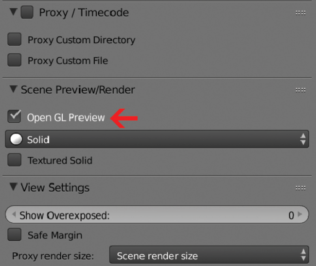
We need to override the 3D viewport and make it display the composition. To do this, we need to use the right-side panel by pressing the N key. In there we need to click on Open GL Preview to disable this option so we can then preview our composition.
Now we can see the composition in the preview window on the Video Sequence Editor.

We can play the video as any other video. Notice that the first time we play the video it is going to be very slow, because Blender has to calculate all our nodes in the composition for each frame. Once one frame is calculated, it gets stored in the memory RAM, so the next time we hit Play it should play in real time.

This technique is very memory intensive. That’s why I suggest exporting to a video file so you can avoid issues such as not having enough memory RAM to load all the frames. Still, it is a good way to preview something quickly if the composition is not terribly huge.
Rendering Limitations
Depth Pass
Cycles is a great render engine, but it has some limitations that could affect drastically our production. The main problem we can face while using Cycles is the lack of anti-aliasing filters when using depth of field and motion blur. These two features of Cycles will provide an incorrect result in the depth pass as well as in the Material Index pass and the Object Index pass.
The result for these passes will be a noisy image:

This image is perfect to show the problem, because this scene has motion blur and depth of field, the two factors that will cause our passes to not be calculated in the right way. Notice how grainy the image above is. That is not a problem of not having enough samples during the rendering. No matter how many samples you add to your render, it will produce these artifacts
Let’s see first how to address the depth pass. Until Blender fixes these issues, here’s a workaround.
We are going to create our own depth pass. The first step is to create a custom material in Cycles. The connections should look like this:
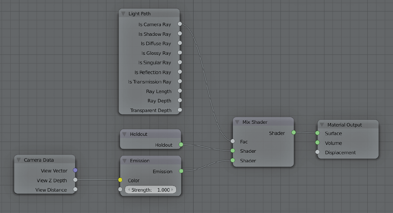
Basically, this material gets the information from the camera’s depth and applies a light value base on that depth information from the camera. To avoid overlapping depth information, we use a holdout to cancel this, and we use a Camera Ray value as the factor for this cancellation. All this might sound a little bit confusing, but as long as you have the connection like this, it should be fine for generating our custom depth pass.
Next we have to assign this material to all the objects in our scene. The fastest way to do this is by using the global material in the Scene setting to overwrite all the materials with our custom one:

If we render our scene now, we should see mostly a white image. That white image has, in fact, depth information with an anti-aliasing filter, exactly what we need. All we need to do now is add some nodes in the compositor to prepare the depth pass for our needs.
This is the node setup we need to create:

Basically, we use our image and we plug in a vector node, in this case the Map Range node. Now we can control the depth information to match the original depth pass. I suggest using a Normalize node connected to the real depth pass to compare and find out the values you will need to add in the From Min and From Max fields.
Due to the fact that we are building the depth pass from a color pass initially, we would need to recreate the background as well. To do that, we can bypass the original alpha channel and recombine this with the image after the vector node. That way we would have an exact copy of the depth pass but without the artifacts.
In the image above I used a split node so you can compare how the original depth pass (on top) looks compared to our custom depth pass (on the bottom).
Notice how grainy the upper half of the image is in comparison with the bottom one.
ID Passes
Object Index and Material Index are the other nodes affected when using depth of field or motion blur in cycles.
We would need a similar approach to the one we used for creating our custom depth pass, but this one is slightly easier.

This test scene has depth of field on the camera. As we can see, it is affecting the ID Mask, creating a very grainy image, and it is not usable for composition. Notice the smooth borders on the original image on the right side.
Basically, we are going to generate our own ID Mask. All we need is a black-and-white image with the elements we want to mask out. The first step is to set our background completely to black:

Once we have the background, we need to create a pure white material and assign it to the objects we want to use for our mask:

Once we have these things set up, all that is left to do is render our pass:

Notice now how smooth the borders on the right side are in comparison with the original ID pass.
With the depth of field workaround and with this ID pass, we should be in good shape to create our compositions in the right way.
Final Notes
At this point we should have all the elements we need together and we should be able to wrap up our project by generating the master file.

What I usually do to generate the master is output the composition as an image sequence in a format that doesn’t compress the image, and then I generate an AVI Raw from this image sequence. I like to do it in this way because if the render crashes while generating the image sequence we can always resume the job on the same frame it crashed on. If we use a movie format and it crashes, then we won’t be able to resume the job and we will need to calculate the frames from the beginning again.
I choose AVI Raw because it is more convenient for me to have the master in a single file while keeping the best quality possible. We should try to work in RAW formats every time we have the chance. Any other format that compresses the information will drop the quality of our work in each step of the process if we use different applications.
Summary
In this last chapter we covered all the nodes individually and we saw a practical example of how to apply some of these nodes. Of course, it would be complicated to apply the exact same workflow I showed in this book to each individual project you might face in the future, but my goal was to show the most important points during the process of creating a visual effects shot in Blender.
The best way to get used to all these nodes and workflows is by practicing constantly. That would be my last suggestion for this book.
I hope that now that we have covered all the different stages of a project, you have a better idea of how to apply all these techniques in your own projects.
Finally I just want to thank you for supporting this book and its author.