
Chapter 8
Giving Models Texture
If you want a more controlled way of adjusting the look of your object than what's described in Chapter 7, then using material settings alone won't get you there. You can use Vertex Paint (V), but if you're working on a model that you intend to animate, Vertex Paint can cause you to have many extraneous vertices just for color. Those vertices end up slowing down the processes of rigging, animating, and even rendering. Also, you may want to have material changes that are independent of the topology and edge flow of your mesh.
For those sorts of scenarios, you're going to want to use textures, which is the focus of this chapter. One thing to note is that, like working with materials (see Chapter 7), there are differences in how you add textures, depending on whether you're rendering with the Blender Internal (BI) or Cycles render engine. As you work through this chapter, I point out where the differences are.
Adding Textures
Generally speaking, a texture is a kind of image that you stretch or tile over the surface of your object to give it more detail without adding more geometry. Not only can textures influence the color of your object, but they can also allow you to make additional adjustments, such as stipulating the shininess of some specific parts of the model. For example, on a human face, skin tends to be shinier across the nose and forehead, and somewhat duller around the eyes. With textures, you can control these sorts of things.
Working with textures in Blender Internal
If you're working with BI, you add and edit textures to a material in Texture Properties, as shown in Figure 8-1.
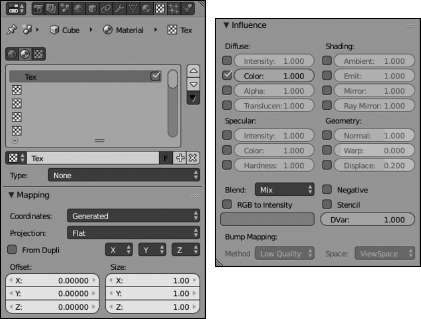
Figure 8-1: Texture Properties.
Like Material Properties, Texture Properties has a Preview panel that displays the texture as you work on it. If you're working from the material and texture in Blender's default scene with the cube, the Preview panel is hidden because the texture type is None. You can change this type in the Context panel with the Type drop-down menu. The texture slots list box at the top of the Context panel is similar to the material slots list box in Material Properties. With these texture slots, you can control the textures applied to your material (which, in turn, is applied to your object). However, unlike material slots, you can't arbitrarily add and remove texture slots. You have exactly 18 texture slots to work with. Left-click any texture slot in the list to choose that slot as the one you want to work on. The texture slots that are populated with a texture display the name of that texture next to its icon. You can customize the name of the texture by double-clicking its texture slot or by editing the texture datablock name field below the texture slot list box. This field is part of a set of datablock controls just like the ones used in Material Properties or Object Properties (see Chapter 7).
When you pick a specific texture type (other than None) by clicking the Type drop-down menu, a Preview panel appears in Texture Properties. By default, the Preview panel has a window that displays your current texture. However, if you left-click the Material button beneath the preview window, it's updated with the same preview panel you see in Material Properties. With this preview type, you can actively see how your texture is mapped to an object without the hassle of bouncing between Material Properties and Texture Properties. If you left-click the Both button, the preview splits to display the texture preview on the left and the material preview on the right. Figure 8-2 shows the three different views of the Preview panel.
Including textures on a Cycles material
If you're rendering with Cycles, Texture Properties doesn't give you very much that's useful. That's because, in Cycles, textures are just other nodes that you add to your node network. It's possible to add a texture from Material Properties from the connector button to the right of any property (it's the button with a small dot in its center). However, you have a lot more control if you do it from the Node Editor by pressing Shift+A ![]() Texture and choosing your desired texture node from the menu. If you compare the list of textures available in Cycles (as shown in Figure 8-3) to those that are available in BI (see Figure 8-4 in the next section), you should notice that they aren't the same. Fortunately, the next section should help demystify some of that for you.
Texture and choosing your desired texture node from the menu. If you compare the list of textures available in Cycles (as shown in Figure 8-3) to those that are available in BI (see Figure 8-4 in the next section), you should notice that they aren't the same. Fortunately, the next section should help demystify some of that for you.

Figure 8-2: From left to right, the Preview panel in Texture Properties allows you to preview your texture, see how your texture is applied in your material, and see a split view of both.
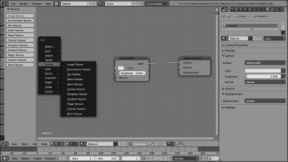
Figure 8-3: If you render with Cycles, you add textures directly in your material node network.
Using Procedural Textures
Blender offers basically two kinds of textures: image-based textures and procedural textures. Unlike image-based textures, where you explicitly create and load an image (or sequence of images) as a texture, procedural textures are created in software with a specific pattern algorithm.
The advantage of procedural textures is that you can quickly add a level of detail to your objects without worrying about the unwrapping described later in this chapter in the section “Unwrapping a Mesh.” The software handles mapping the texture to the mesh for you. Another advantage of procedurals is that they're resolution independent; they don't get blurry or pixelated when you zoom in very close.
Of course, procedurals can be a bit more difficult to control than image-based textures. For example, if you have a character with dark circles under his eyes, getting those circles to show up only where you want can be pretty tough, maybe even impossible if you're only using procedurals. So the ideal use for procedural textures is as broad strokes where you don't need fine control. Procedural textures are great for creating a foundation or a base to start with, such as providing the rough texture of an orange rind's surface.
Understanding Blender Internal's procedurals
Besides the None texture type, Blender Internal has 14 procedural texture types that you can work with, accessible through the Type drop-down menu in Texture Properties. In addition to these procedurals, you can also choose Image as a texture type. Figure 8-4 shows all available texture types.
The following are brief descriptions of each type of procedural texture:
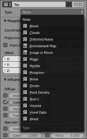
Figure 8-4: The available textures you can use that are built into Blender Internal.
Roughly half of all the procedural textures share an option labeled Basis, short for noise basis. The noise basis is a specific type of pseudorandom pattern that influences the appearance of a procedural texture. Noise basis has two controls:
- Basis: The Basis menu allows you to choose one of several algorithms for generating noise.
- Nabla value: The Nabla value offers more advanced control of the sharpness or smoothness of the texture when it's applied to the material.
The types of noise basis fall roughly into three different kinds of noise:
- Cell noise: A blocky, pixelated type of noise, cell noise stands apart from the other noise basis types because it's the least organic-looking. If you're interested in a very digital-looking texture, this type is the one to choose.
- Voronoi family: These noise types include Crackle, F2-F1, F4, F3, F2, and F1 and are all roughly based on the same algorithm. A primary attribute of Voronoi noise is a somewhat distinct partitioning throughout the texture with generally straight lines. This partitioning is most apparent in the Voronoi Crackle noise basis. These noise types are good for hammered metal, scales, veins, and that dry desert floor look.
- Cloudy noise: Cloudy is my own terminology, but it includes the Improved Perlin, Original Perlin, and Blender Original noise basis types. These types of noise tend to have a more organic feel to them and work well for generic bump textures and clouds or mist.
- Clouds texture: The Clouds texture is a good general-purpose texture. You can treat the Clouds texture as a go-to texture for general bumps, smoke, and (of course) clouds.
- Distorted Noise texture: The Distorted Noise texture is pretty slick. Actually, strike that; this type of texture is best suited to very rough, complex surfaces. The way the Distorted Noise texture works is pretty cool, though. You use one procedural noise texture, specified by the Noise Distortion menu, to distort and influence the texture of your noise basis. With this combination, you can get some really unique textures.
- Environment Map texture: An environment map is a way of using a texture to fake reflections on your object. It works by taking the position of a given object and rendering an image in six directions around that object: up, down, left, right, forward, and back. These images are then mapped to the surface of your object. So, an environment map isn't exactly a procedural texture in the traditional sense, but because the environment images are taken automatically, I say it's part procedural and part image-based. Environment maps aren't as accurate as using ray traced reflection (see Chapter 7), but they can be quite a bit faster. So if you need a generically reflective surface that doesn't need to be accurate, environment maps are a handy tool that keeps your render times short. In the Environment Map panel, the Viewpoint Object field is set, by default, to be the object that you intend on mapping the texture to. However, sometimes you can get a better reflective effect by using the location of a different object, such as an Empty. Using an Empty as a Viewpoint Object is particularly useful when applying an environment map to an irregular surface.

When using environment maps, make sure that you do two things. First, choose the Reflection option from the Coordinates drop-down menu in the Mapping panel of Texture Properties. Second, make sure the Environment Map check box in the Shading panel of Render Properties is enabled. Unless you do both of these things, your environment map won't work properly.
- Magic texture: At first glance, the Magic texture may seem to be completely useless — or at the very least, too weird to be useful. However, I've found quite a few cool uses for this eccentric little texture. If you treat the Magic texture as a bump map or a normal map, it works well for creating a knit texture for blankets and other types of cloth. If you stretch the texture with your mapping controls, you can use it to recreate the thin filmy look that occurs when oil mixes with water. And, of course, you can use it to make a wacky wild-colored shirt.
- Marble texture: This texture has a lot of similarities with the Wood texture covered later in this section. However, the Marble texture is a lot more turbulent. You can use the Marble texture to create the look of polished marble, but the turbulent nature of the texture also lends itself nicely to be used as a fire texture and, to a lesser extent, the small ripples you get in ponds, lakes, and smaller pools of water.
- Musgrave texture: This procedural texture is extremely flexible and well suited for organic materials. You can use the Musgrave texture for rock cracks, generic noise, clouds, and even as a mask for rust patterns. As a matter of fact, with enough tweaking, you can probably get a Musgrave texture to look like nearly any other procedural texture. Of course, the trade-off is that this texture takes a bit longer to render than most of the other textures.
- Noise texture: Noise is the simplest procedural texture in Blender. (Well, the None texture type is probably simpler, but it's not very useful.) This texture has no custom controls of its own; it's simply raw noise, which means that you'll never get the same results twice using this texture. Each time you render, the noise pattern is different. This lack of predictability may be annoying if you're looking to do a bump map. However, if you're looking to have white noise on a TV screen, this texture is perfect.
- Ocean: This texture is for the specific (and somewhat advanced) case where you have a scene that has an object that's using the Ocean modifier. (I briefly cover the Ocean modifier in Chapter 5; it's basically a modifier that you use to make a mesh look like the surface of a large body of water.) The Ocean texture is a procedural texture based on the geometry that the modifier generates.
- Point Density texture: The Point Density texture is used primarily with Blender's particle system to generate volumetric textures. These kinds of materials are well suited for creating smoke and clouds. (See Chapter 13 for more on Blender's particle system.)
- Stucci texture: Stucci is a nice organic texture that's most useful for creating bump maps. The Stucci texture is great for industrial and architectural materials like stucco, concrete, and asphalt. This texture is also handy if you just want to give your object's surface a little variety and roughen it up a bit.
- Voronoi texture: The Voronoi procedural texture doesn't have a noise basis because it's the same algorithm that is used for the Voronoi noise basis options, but with more detailed controls. It may be helpful to think of those basis options as presets, whereas this texture gives you full control over what you can do with the Voronoi algorithm. The Voronoi texture is pretty versatile, too. You can use it to create scales, veins, stained glass, textured metals, or colorful mosaics.
- Voxel Data texture: A voxel, short for volumetric pixel, is the threedimensional equivalent to a pixel. The Voxel Data texture type is primarily used in Blender for smoke simulations, but you can also use it for other forms of volumetric data, such as the image slices provided by medical CT scans.
- Wood texture: The Wood texture is a bit of a misnomer. Sure, you can use it to create textures that are pretty close to what you see on cut planks of wood. However, the Wood texture has a lot more versatile uses. You can use the Wood texture to create nearly any sort of striped texture. I've actually even used it to fake the look of mini-blinds in a window.
Discovering procedurals in Cycles
Like in BI, you also have a set of procedural textures available in Cycles. Many of them are the same as their BI counterparts, though there are a few different ones. The following is a list of procedural textures available in Cycles:
A powerful and under-recognized tool in Blender is the ramp. A ramp is basically a gradient, and its editor interface is used in procedural textures, ramp materials, the material node editor, and even the node compositor. For BI materials, you can enable ramps by clicking the Ramp check box tab in the Diffuse and Specular panels of Material Properties. For procedural textures, the Ramp check box appears in the Colors panel. In the Node Editor, you can add ColorRamp node by using Shift+A ![]() Converter
Converter ![]() ColorRamp. Ramps are a great way, for example, to adjust the color of the stripes in the Wood texture or determine which colors you want to use for your Blend texture. You can even use ramps to have a more controlled custom toon coloring than you can get with the diffuse or specular Toon shaders. The ramp editor works much like gradient editors in other programs. By default, it starts with a color positioned at either end of a colorband bar, and the color smoothly transitions from one side to the other. The color can be any value in the RGB spectrum, and, using the color picker, you also can control its transparency with the alpha value.
ColorRamp. Ramps are a great way, for example, to adjust the color of the stripes in the Wood texture or determine which colors you want to use for your Blend texture. You can even use ramps to have a more controlled custom toon coloring than you can get with the diffuse or specular Toon shaders. The ramp editor works much like gradient editors in other programs. By default, it starts with a color positioned at either end of a colorband bar, and the color smoothly transitions from one side to the other. The color can be any value in the RGB spectrum, and, using the color picker, you also can control its transparency with the alpha value.
To change a color, first select it by either left-clicking its position in the colorband or adjusting the position value in the number field above the colorband. Color positions count up from left to right, starting at 0. So with the default arrangement, the transparent black color on the left is 0, and the white color on the right is 1. After you select the color, you can change its value by left-clicking the color swatch and using the color picker. To move the color position, you can left-click and drag it along the colorband, or you can adjust the Pos, or Position, value after you've selected it.
To add a new color position, left-click the Add button. A color position appears at the halfway point in the colorband. You can delete any position by selecting it and left-clicking the Delete button.
It may not seem like much, but mastering ramps and knowing when to use them makes your workflow for adding materials and textures much faster.
Understanding Texture Mapping
After you create your texture, be it procedural or image-based, you're going to have to relate that texture to your material and, by extension, the surface of your object. This process is called mapping. Mapping basically consists of relating a location on a texture to a location on the surface of an object. This section walks you through the process of texture mapping, both in BI and in Cycles. Regardless of which render engine you're using, texture mapping is conceptually the same; the main differences are in user interface. That being the case, I strongly recommend that you read through both sections. I make sure to point out when something only applies to one of the renderers and not the other.
Applying textures when using Blender Internal
If you're using BI, the mapping controls are located in Texture Properties in the Mapping and Influence panels, as shown in Figure 8-5. The next two sub-sections explain how to use the properties in these panels to wield full control over how your textures are applied to your objects.

Figure 8-5: The Mapping and Influence panels in Texture Properties when you're rendering with BI.
The Mapping panel
The Mapping panel controls how the texture is mapped to the object, defining how the texture coordinates are projected on it. The most important button is the drop-down menu labeled Coordinates. The following list explains the types of coordinate mapping available:
In addition to these map inputs, you can also control what's called the texture projection. Texture projection, along with the map input, controls how the texture is applied to the mesh for everything except UV textures. Because UV textures explicitly map a texture coordinate to a coordinate on the surface of your object, changes to projection don't have an effect.
Blender has four different types of projection:
Figure 8-6 shows a set of primitive objects with Flat, Cube, Tube, and Sphere projection.

Figure 8-6: Projecting textures in different ways on the same set of 3D objects.
At the bottom of the Mapping panel are fields that give you finer control over how your texture is positioned on your object. The Offset values define an offset in the X, Y, and Z directions. And the Size values scale the texture in each of those directions.
The Offset and Size values aren't relative to the global or local coordinates in the 3D View. They're actually relative to the texture image itself. The X and Y values are horizontal and vertical, whereas the Z value is a depth value into the texture. The Z values don't have a lot of influence unless the texture is a procedural texture with a noise basis because many of those textures actually have 3D depth information.
The Influence panel
Not only do you control how a texture is mapped to an object, but you also control how that texture affects the material in BI, thanks to the controls in the Influence panel.
 Each Influence value is enabled using a check box to the left of each slider. After you enable a check box, you can adjust its slider to dictate the level of influence. Most sliders span both positive and negative values, typically from –1 to 1. Using this range, values greater than 0 enable the option and increase its effect, but negative values indicate that the texture's effect on the material is inverted.
You can use any combination of the following options:
- Diffuse controls: Use these values to dictate how your texture influences various attributes of your material's diffuse shader. You have four options:
- Intensity: Influences the intensity value in the material's diffuse shader, controlling how much light the material reflects.
- Color: Affects the material's diffuse color.
- Alpha: Controls the transparency and opacity of the material.
- Translucency: Affects the amount of translucency in the material.
- Specular controls: These controls are like the Diffuse values, but they relate specifically to the material's specularity. You have three options
- Intensity: Influences the strength in the material's specular shader.
- Color: Affects the material's specular color.
- Hardness: Affects the specular hardness values for the specular shaders that support it.
- Shading controls: The values here dictate how your textures influence corresponding values in the Shading panel of the Material Properties. You have four options:
- Ambient: Affects the amount of ambient light the material gets.
- Emit: Affects the material's emit value.
- Mirror Color: Affects the material's mirror color.
- Ray Mirror: Influences the amount of ray traced reflection that the material has.
- Geometry controls: With the values in this section, your textures can actually deform geometric elements of your object, be they the face normals or the location of faces themselves. You have three options:
- Normal: Influences the direction of the surface normals on the material. Enabling this check box enables bump mapping. This option can give your object the appearance of much more detail without the computational slowdown of additional geometry.
- Warp: This value actually controls how one texture in the list of textures affects the next one in the stack. Higher Warp values cause this texture to influence the coordinates of the next texture in the stack.
- Displace: This option is similar to the Normal option, except that it actually moves the geometry of the object based on the texture map. Whereas bump mapping only makes it look like geometry is added and moved around by tricking out the surface normal, displacement actually moves the geometry around. The downside to Blender's displacement is that you have to have the vertices already in place to move around. Blender won't create the vertices for you on the fly. You can use the Subdivision Surface modifier to get around this a bit, but creating your additional vertices with that tool definitely increases your render times.
Another thing to note is that you can't see the results of texture displacement in the 3D View unless you use Rendered viewport shading. If you want to see the shifted geometry in a different viewport shading (such as Solid or Wireframe), I recommend that instead of using this texture control, you use the Displace modifier. You can read more on modifiers in Chapter 5.
Mapping textures when using Cycles
If you're using Cycles, there's a Mapping panel in Texture Properties that's similar to the corresponding panel when rendering with BI. However, you have far more control using the Texture Coordinates node in concert with a Mapping node, as shown in Figure 8-7.
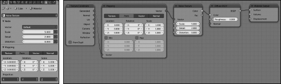
Figure 8-7: If you render with Cycles, you can control your texture mapping from a Mapping panel in Texture Properties (left), but you have far more control using the node editor (right).
Conceptually, there are a lot of similarities between mapping textures on your object in BI and doing the same thing in Cycles. If you skipped over the previous section on applying textures using BI, I strongly recommend that you go back and read it. The content of that section is very relevant to this one. Most of the differences are in terms of user interface. Rather than making your adjustments from a handful of panels in Texture Properties, you're connecting a series of nodes together.
Using texture coordinates
In Cycles, texture mapping is handled in the nodes (particularly the Texture Coordinates node and the Mapping node), while the Cycles equivalent to Bl's Influence panel is implicit, based on how you wire the nodes together.
As shown in Figure 8-7, the basics of it work like this:
- Add a Texture Coordinate node (Shift+A
 Input Texture Coordinate) to your material in the Node Editor.
Most of the texture coordinates listed in the preceding section are available: Generated, Normal, UV, Object, Camera, Window, and Reflection. There are a few differences, but they aren't exceedingly significant. I cover the differences later in this section.
- Connect the socket of your desired texture coordinate to the Vector input socket on your chosen Texture node in your material.
The Texture node could be any of the ones available in the Node Editor when you press Shift+A
Texture. All of them have a Vector input socket. - Optionally, add a Mapping node (Shift+A Vector Mapping) and wire it on the noodle between your Texture Coordinate node and your Texture node.
The Mapping node (look back to Figure 8-7 to see it) is what gives you more control over the texture coordinates on your object. It's akin to the Offset and Size values in Bl's Mapping panel, but with even more controls (such as giving the texture coordinates an arbitrary rotation).
- Connect the Color output socket on your Texture node to the Color input socket on your desired shader node.
This is Cycles' equivalent to Bl's Influence panel. If you want your texture to influence the color of your diffuse shader, you explicitly connect it to the Diffuse BSDF node's Color socket. Want your grayscale texture to influence the roughness of your glossy shader? Connect it to the Roughness socket on a Glossy BSDF. In a way, using nodes is a much more direct way of mapping and applying textures to a material, because you can zoom out on the node network and get a really complete understanding of the material all at once.
You may be reading all of this and find yourself saying, “Great, but how do I fake having more detail with a bump map or a normal map? In BI, I just need to work with the Geometry properties, like Normal and Displace in the Influence panel.” Fortunately, that's also easy in Cycles. If you have a grayscale texture that you want to use as a bump map, all you need to do is wire it to the Displacement socket of the Material Output node, as shown in Figure 8-8. Easy!

Figure 8-8: Bump mapping is easy in Cycles. Just connect your texture to the Displacement socket of your Material Output node.
If you want to have different bumps on different shaders in the same material, that's also possible, though a bit more complex. Rather than wire your grayscale texture to the Displacement socket on the Material Output node, add a Bump node (Shift+A ![]() Vector
Vector ![]() Bump) and wire your texture to its Height socket. Then wire the Normal output socket of your Bump node to the Normal input socket of any shader node. And voilà! Custom bumpiness on any shader!
Bump) and wire your texture to its Height socket. Then wire the Normal output socket of your Bump node to the Normal input socket of any shader node. And voilà! Custom bumpiness on any shader!
Looking back at the Texture Coordinates node, you may notice that quite a few of the coordinate systems listed in the previous section appear to be missing. Fortunately, a few of them — including Global coordinates and Tangent coordinates — are available (along with a few bonus coordinate systems); you just need to use a different node. Specifically, you need to use the Geometry node. This is for organizational reasons. Basically, global coordinates and tangent coordinates have more to do with object geometry than they do with the texture. They're really independent of the texture. For that reason, Blender's developers felt it made more sense to organize them in the Geometry node. In fact, the Geometry node gives more than just those options. If you add it by pressing Shift+A ![]() Input
Input ![]() Geometry, you have the following sockets available:
Geometry, you have the following sockets available:
Object coordinates in Cycles and the UV Project modifier
Aside from Stress coordinates, the only other coordinate system that Cycles doesn't seem to have — or at least doesn't have as fully-featured as BI — are Object coordinates. There is the Object socket on the Texture Coordinates node, but unfortunately, there's no way to explicitly tell Cycles to use another object's coordinates for projecting a texture on your object. This means that the use for Object coordinates is a bit more limited. In Cycles, they're primarily useful for getting undistorted procedural textures applied to your object.
There are two main differences between Generated coordinates and Object coordinates:
So there's a bit of a trade-off here. Fortunately, this trade-off isn't a frequent problem. If an object uses deforming animation (see Chapters 11 and 12), you typically don't use procedural textures, so it's less common to use Object mapping on them.
But what if you really want to place a texture on your object in Cycles with the same decal-like effect that Object coordinates give you in BI? For that, you need to use a workaround. Namely, you should make use of the UV Project modifier. The UV Project modifier treats one or more objects as external “projectors” that project a texture on your object much like a movie projector shows a movie on a screen. The only limitation is that your object must already be UV unwrapped. If you're working with a NURBS surface, the unwrapping already is done automatically. However, for mesh objects — the more common case — you need to unwrap manually (see the next section).
Assuming that your object already is unwrapped, use the following steps to project a texture on your mesh with the UV Project modifier:
- Add an Empty object to your scene (from the 3D View, Shift+A Empty Plain Axes).
This Empty object is what you'll use as your “projector”. The image texture will appear to project along the Empty's local Z-axis. I recommend giving this Empty a custom name like
Projector, but you can leave it with its default name. Just remember that name. - With your object selected, add a UV Project modifier from Modifier Properties (Modifier Properties Add Modifier UV Project).
I know I'm drilling the point, but again, make sure that your object is already unwrapped.
- Fill in fields on the UV Project modifier.
- (Optional) If your mesh has more than one UV unwrapping, use the UV Map field to choose the UV layer on which you want the UV Project modifier to work.
- Enable the Override Image check box.
- In the Object field below the Projectors property, type or pick the name of the Empty you're using as a projector.
- Set up your material to use UV textures in the Node Editor (Shift+F3).
- Add an Image Texture node (Shift+A Texture Image Texture) and load an image texture from your hard drive.
- Add a Texture Coordinates node (Shift+A Input Texture Coordinates).
- Connect the UV socket in the Texture Coordinates node to the Vector input socket on the Image Texture node.
- (Optional) Add a Mapping node and place it inline on the noodle between the Texture Coordinates node and the Image Texture node. Enable the Min and Max check boxes in this node.
By default, UV mapped image textures tile, or repeat, when they reach the end of the image. If you don't want this repeating behavior, enabling these check boxes in the Mapping node prevents it.
- Add an Image Texture node (Shift+A
- Connect the Color output socket of the Image Texture node to the Color input socket of the Diffuse BSDF node.
With those steps complete, you should be able to move the Empty around and see the texture slide around the surface of your object in the 3D View.
To properly position the texture, split the 3D View into two and display one of the 3D Views in Rendered viewport shading (Shift+Z). This way, you can both see your projector Empty and see the results of moving it around.
Figure 8-9 shows what your Blender screen layout might look like.
When your texture (in this kind of usage, it's sometimes called a decal) is applied how you like it, you may want to consider vertex parenting your projector Empty to some nearby vertices on your mesh (see Chapter 4 for more on vertex parenting). I especially recommend vertex parenting if your object is going to be animated. This way, when you animate your object, the projector Empty goes along with it and the decal doesn't get distorted.

Figure 8-9: Positioning a texture on an object using the UV Project modifier.
Alternatively, if you create a separate UV layer in the UV Maps panel of Mesh Properties, you can apply the UV Project modifier on that layer. Then, using those modified UV coordinates (covered in the last section of this chapter, “Using UV Textures”), your decal texture is mapped without any need for that projector Empty to remain in the scene.
Unwrapping a Mesh
The most precise type of mapping you can use is UV mapping. UV mapping also allows you to take advantage of other Blender features, such as Texture Paint mode, the UV Project modifier (see the preceding section), and texture baking. With NURBS surfaces, you get UV coordinates for free as part of their structure. However, Blender is predominantly a mesh editor, and in order to get proper UV coordinates on your mesh objects, you must put those meshes through a process known as unwrapping.
To understand this process, think about a globe and a map of the world. The map of the world uses the latitude and longitude lines to relate a point on the three-dimensional surface of the globe to the two-dimensional surface of the map. In essence, the world map is an unwrapped texture on the globe, whereas the latitude and longitude lines are the UVs. Figure 8-10 shows a visualization of this process.
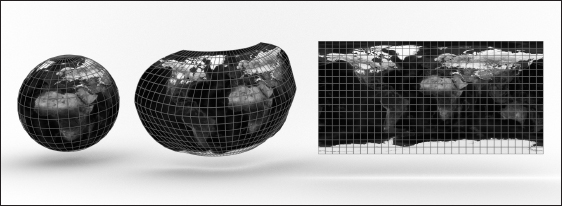
Figure 8-10: UV unwrapping a 3D mesh is like making a map of the Earth (image texture credit: NASA).
Marking seams on a mesh
You unwrap a mesh in Blender by selecting all vertices (A) and, while in Edit mode (Tab), either pressing U or choosing UV Mapping ![]() Unwrap in the Tool Shelf. You then see a menu with a handful of options.
Unwrap in the Tool Shelf. You then see a menu with a handful of options.
However, despite the menu's variety of options, unless your mesh is simple or a special case, you should use the first menu item, Unwrap. Blender has very powerful unwrapping tools, but to take full advantage of them, you need to first define some seams. Remember that you're basically trying to flatten a 3D surface to a 2D plane. In order to do so, you need to tell Blender where it can start pulling the mesh apart. This location on your mesh is a seam. If you were unwrapping a globe, you might choose the prime meridian as your seam. I like to think about seams for unwrapping in terms of stuffed animals, such as a teddy bear. The seam is where the bear is stitched together from flat pieces of cloth.
To add a seam to your mesh, use the following steps:
- Tab into Edit mode and switch to Edge Select mode (Tab Ctrl+Tab Edges).
You can also add seams from Vertex Select mode, but I find that it's easier in Edge Select.
- Select the series of edges you want to make into a seam (right-click Shift+right-click).
Using edge loop selection (Alt+right-click) can really be helpful here. Everyone has their own tastes when it comes to defining seams, but a good general rule is to put the seams on parts of the mesh that are easier to hide (for example, behind the hairline on a character, the undercarriage of a car, and so on).
Though edge loop selection can be helpful, it sometimes selects more edges than you want. So a handy feature in Blender is Select
Shortest Path in the 3D View's header menu (you can also get to this operator by searching for it using Blender's integrated search when pressing Spacebar). With this feature, if you select two vertices or edges, Blender will select the shortest path of edges from one to the other. That path often works very well as a seam for unwrapping. - Use the Edge Specials menu to make the seam (Ctrl+E Mark Seam or, in the Shading/UVs tab of the Tool Shelf, UV Mapping Mark Seam).
Seams on your mesh are highlighted in red. If you mistakenly make a seam with the wrong edges, you can remove the seam by selecting those edges (right-click) and pressing Ctrl+E
Clear Seam or choosing UV Mapping Clear Seam in the Shading/UVs tab of the Tool Shelf.
With your seams defined, you're ready to unwrap your mesh. In order to see what you're doing, though, you should make a couple changes to your screen layout:
- Change the viewport shading of your 3D View to textured (Alt+Z).
- Split off a new area and change it to be a UV/Image Editor (Shift+F10).
Alternatively, you can switch to the default UV Editing screen that ships with Blender by clicking the screen datablock at the top of your Blender window.
Your layout should look something like what is shown in Figure 8-11.

Figure 8-11: A typical screen layout for UV unwrapping and editing.
Adding a test grid
The next thing you need is an image for mapping to your mesh. Using a test grid — basically an image with a colored checkerboard pattern — is common practice when unwrapping. A test grid is helpful for trying to figure out where the texture is stretched, or unevenly mapped, on your mesh. To add a test grid, go to the UV/Image Editor and choose Image ![]() New or press Alt+N. A floating panel like the one in Figure 8-12 appears. Name the image something sensible, such as
New or press Alt+N. A floating panel like the one in Figure 8-12 appears. Name the image something sensible, such as Test Grid, and choose either Color Grid or UV Grid from the Generated Type drop-down menu. Leave the other settings at their defaults for now. The UV/Image Editor updates interactively.

Figure 8-12: The New Image floating panel for adding a test grid image.
You can unwrap your mesh without adding a test grid, but a test grid gives you a good frame of reference to work from when unwrapping.
Also, note the height and width of the test grid image. The most obvious thing is that it's square; the height and width are equal. When you create the image, you can make it nonsquare, but UV texturing is often optimized for square images (particularly in some game engines), so consider where your 3D model will be used; if it makes sense, keep its image textures square.
Another tip that helps performance when working with UV textures (especially for video games) is to make your texture size a power of two — a number that you get by continually multiplying 2 by itself. The default size is 1,024 pixels square, or 210. The next larger size is 2,048 (211) pixels, and the next size down would be 512 (29) pixels. This strange sizing is because computer memory is measured and accessed in values that are powers of two. So even if you're not using your 3D model in a video game, it's still a good idea to stick to the power of two guideline. It's an easy guide to stick to, and every, every little bit of performance optimization helps, especially when you start rendering (see Chapter 14).
Generating and editing UV coordinates
Alrighty, after marking seams on your mesh and adding a test grid for reference, now you're ready to unwrap your mesh. From Edit mode, unwrapping is pretty simple:
- Select all vertices (A).
Remember that the A key is a toggle, so you may have to hit it twice to get everything selected.
- Unwrap the mesh (U Unwrap).
Poof! Your mesh is now unwrapped! If you used a Suzanne to practice unwrapping, you may have something that looks like Figure 8-13.
From this point, you can edit your UV layout to arrange the pieces in a logical fashion and minimize stretching. You can tell a texture is stretched with your test grid. If any of the squares on the checkerboard look distorted or grotesquely nonsquare-shaped, stretching has taken place. If you don't see the test grid texture on your monkey, make sure that you're using Textured Viewport Shading (Alt+Z). The controls in the UV/Image Editor are very similar to working in the 3D View. The Grab (G), Rotate (R), and Scale (S) hotkeys all work as expected, as well as the various selection tools like Border select (B), Circle select (C), and Edge Loop Selection (Alt+right-click). There's even a 2D cursor like the 3D cursor in the 3D View to help with snapping and providing a frame of reference for rotation and scaling.

Figure 8-13: An unwrapped Suzanne head.
If you're trying to fix stretching, you may notice that moving some vertices in your UV layout to fix stretching in one place distorts and causes stretching in another part. To help with this problem, Blender offers you two features: vertex pinning (P) and Live Unwrap (UVs ![]() Live Unwrap). They actually work together. The workflow goes something like these steps:
Live Unwrap). They actually work together. The workflow goes something like these steps:
- In the UV/Image Editor, select the vertices that you want to define as control vertices (right-click Shift+right-click).
The control vertices are usually the vertices at the top and bottom of the center line and some corner vertices. I tend to prefer using vertices that are on the seam, but sometimes using internal vertices is also helpful.
- Pin these selected vertices (P).
The vertices now appear larger and are a bright red color. If you want to unpin a vertex, select it (right-click) and press Alt+P.
- Turn on Live Unwrap (UVs Live Unwrap).
If a check mark appears to the left of this menu item, you know it's currently enabled.
- Select one or more pinned vertices and move them around (right-click G).
As you edit these pinned vertices, all the other vertices in the UV layout automatically shift and adjust to compensate for this movement and help reduce stretching.
When using pinned vertices and Live Unwrap, selecting and moving unpinned vertices isn't normally going to be very helpful. The moment you select and move a pinned vertex, any manual changes you made to unpinned vertices are obliterated.
The UV/Image Editor also offers you the ability to edit your UVs, like sculpting in the 3D View (see Chapter 5). To toggle UV sculpting, choose UVs ![]() UV Sculpt from the UV/Image Editor's header menu or press Q. Options for UV sculpting are in the Tools tab of the UV/Image Editor's Tool Shelf (T). If you try to sculpt and you don't see your UV vertices moving, try disabling the Lock Borders check box Tool Shelf
UV Sculpt from the UV/Image Editor's header menu or press Q. Options for UV sculpting are in the Tools tab of the UV/Image Editor's Tool Shelf (T). If you try to sculpt and you don't see your UV vertices moving, try disabling the Lock Borders check box Tool Shelf ![]() Tools
Tools ![]() UV Sculpt.
UV Sculpt.
You can actually see the changes you make in the UV/Image Editor in real time if you left-click the Lock button in the header of the UV/Image Editor (it's the last button, with an icon of a lock). The Lock button is enabled by default. Of course, if your computer seems to be performing slowly with this option on, you can always disable it by left-clicking it.
Figure 8-14 shows the unwrapped Suzanne head from before, after a bit of editing and adjustment.

Figure 8-14: An unwrapped and [mostly] stretchless Suzanne head.
Painting Textures Directly on a Mesh
If you followed the earlier sections in this chapter, you have an unwrapped mesh and a texture on it that doesn't stretch. Woohoo! But say that, for some crazy reason, you don't want your object to have a checkerboard as a texture, and you want to actually use this UV layout to paint a texture for your mesh. You can either paint directly on the mesh from within Blender or export the UV layout to paint in an external program like Krita or Photoshop. I actually prefer to use a combination of these methods. I normally paint directly on the mesh in Blender to rough out the color scheme and perhaps create some bump and specularity maps. Then I export that image along with an image of the UV layout to get more detailed painting done in an external program.
Preparing to paint
After you have an unwrapped mesh, the starting point for painting textures on it is Blender's Texture Paint mode. Activate Texture Paint mode by left-clicking the mode button in the 3D View's header. Alternatively, if you have the Pie Menus add-on enabled, Texture Paint mode is available from the pie that appears when you press Tab. When you activate Texture Paint mode and look to the 3D View's Tool Shelf, you may see some errors at the top of the Tools tab. There will be a warning that says “Missing Data.” If you haven't unwrapped your mesh, there will be a message that says “Missing UVs”. In that case, Blender offers a button, Add Simple UVs, that quickly unwraps your mesh for you without seams.
Although it's tempting to use this means of unwrapping, rather than the steps covered in the preceding section, I don't recommend it (especially if you intend on finalizing your image texture in a 2D painting program like Krita or Photoshop). That said, Blender's texture painting tools have gotten a lot more powerful over the years. So if you plan on painting your textures only within Blender, the simple UV unwrap you get from clicking this button may be sufficient for your needs. As always, it's about knowing what you want and accepting certain trade-offs based on that knowledge.
The other missing data warning that you may get is one that states you're “Missing Texture Slots.” This warning is because you need an image texture (even a blank one) so Blender knows what you're painting on. You can add an image texture to your material as described in the first section of this chapter, but there's also a convenience button labeled Add Paint Slot directly below the warning in the Tool Shelf. Left-clicking this button reveals a list of texture types to apply to your material. After you pick one (such as Diffuse Color), Blender shows a floating panel like the one for adding a new image in the UV/Image Editor. Decide on the size and type (Blank, UV Grid, or Color Grid) of your image texture and left-click the OK button at the bottom of the panel. Blender then automatically generates your image texture and applies it to your material. (Blender automatically connects sockets if you're using Cycles or enables the correct check boxes in the Influence panel of Texture Properties if you're using BI.) Figure 8-15 shows the Tools tab of the Tool Shelf in Texture Paint mode before and after these warnings are resolved.
After you add your first paint slot, you can add additional ones from the Slots tab of the 3D View's Tool Shelf. Many Blender artists like to use these slots like layers in a 2D painting program like Krita or Photoshop.
Working in Texture Paint mode
From here, things are pretty similar to Vertex Paint mode (see Chapter 7), with a few exceptions. The Tools tab of the Tool Shelf updates with an array of paint options, but the specific content of the Tool Shelf has some differences from Vertex Paint. The Brush panel is largely the same, though with a few more preset brushes.
There's also a Texture panel in the Tool Shelf where you can actually define a texture for your brush, so you're not just painting flat colors. Regardless of whether you're rendering with BI or Cycles, you define brush textures in Texture Properties. In fact, editing brush textures is the only thing you can do in Texture Properties if you're using Cycles. If you're rendering with BI, there are three buttons at the top of Texture Properties where you can choose the type of texture you want to edit: world textures, material textures, or brush textures. Using Blender textures to paint UV textures gives your painting quite a bit more flexibility.

Figure 8-15: On the left, the Tools tab of the Tool Shelf in Texture Paint mode if your material has no UVs or textures applied to it. On the right is the same tab after resolving those issues.
When you're in Texture Paint mode, start painting directly on your mesh by left-clicking and dragging your mouse cursor on it. If you have a test grid image already loaded as your image, your paint strokes appear directly on this image. In fact, if you still have the UV/Image Editor open, you can watch your image get updated as you paint your mesh. And actually, you can paint directly on the UV image itself by enabling painting in the UV/Image Editor. Enable painting in the UV/Image Editor from the editing context drop-down menu in the header. It defaults to View; by left-clicking that context dropdown menu, you can also choose the Paint or Mask contexts. With Image Painting enabled in the UV/Image Editor, the Tools tab of the Tool Shelf in that editor has the same painting controls that are available in the corresponding Tool Shelf tab of the 3D View.
Because of this cool ability to paint in both the 3D View and the UV/Image Editor, when I paint textures in Blender, I like to have my screen laid out like Figure 8-16. I have the 3D View and UV/Image Editor both in Texture Paint mode. If I need to tweak a texture for my brush, I temporarily switch one of the areas to a Properties editor (Shift+F7) and make adjustments from Texture Properties, then switch back (Shift+F5 for the 3D View, shift+F10 for the UV/Image Editor). This layout and workflow is a pretty effective way to get work done.

Figure 8-16: A good screen layout for texture painting directly on your mesh.
Saving painted textures and exporting UV layouts
Of course, despite the cool things that you can do with Blender's Texture Paint mode, there are some things that are easier in a full-blown 2D graphics program like Krita or Photoshop. To work on your image in another program, you need to save the texture you already painted as an external image. You should also export your UV layout as an image so that you have a frame of reference to work from while painting.
To save your painted texture, go to the UV/Image Editor and choose Image ![]() Save As. A File Browser appears, allowing you to save the image to your hard drive in any format you like. I prefer to use PNG because it has small file sizes and lossless compression.
Save As. A File Browser appears, allowing you to save the image to your hard drive in any format you like. I prefer to use PNG because it has small file sizes and lossless compression.
Regardless of whether you're continuing to paint on your texture in an external program, I strongly recommend that you save your image file externally. Not only does doing so reduce the size of your .blend file, but it also serves as a completion milestone that you can always come back to, like a save point in a video game. And from the perspective of a person who's paranoid about data safety (like me), external saving ensures that your texture is preserved in the event that your .blend file become corrupt or unreadable. It's a credo I have whenever I do anything with a computer: Save early, save often, save multiple multiple copies.
 If you don't explicitly save your image texture, it will not be saved with your
 .blend file. If you close Blender and then re-open the file, all of your painting will be lost. There are only two workarounds for this:
- Save your image externally. As described in the preceding paragraphs, choose Image Save As from the UV/Image Editor.
- Pack your image in your
.blendfile. Also from the UV/Image Editor, choose Image Pack As PNG. This bundles the image in your .blendfile so it will be there when you re-open the file.
In either case, if you continue to paint on your texture in Blender, you will need to continue to either save it externally or repack it to avoid losing your changes.
With your image saved, the next thing you probably want out of Blender for your 2D image editor is the UV layout of your object. To export the UV layout, you need to be in the UV/Image Editor while in Edit mode (Tab). Navigate to UVs![]() Export UV Layout. This brings up a File Browser where you can choose where to save your UV layout on your hard drive.
Export UV Layout. This brings up a File Browser where you can choose where to save your UV layout on your hard drive.
This UV export feature gives you the option (in the last panel of the left sidebar in the File Browser) to save in the familiar PNG image format as well as two other formats: SVG and EPS. Both SVG (Scalable Vector Graphics) and EPS (Encapsulated PostScript) are vector image formats. If your UV layout is in a vector format, you can scale it to fit any image size you need without losing any resolution. So you can use the same UV layout file to paint both low-resolution and high-resolution textures.
Most graphics applications should be able to read SVG files just fine. If you run into a problem, though, I recommend opening the SVG in GIMP (www.gimp.org) or Inkscape (www.inkscape.org). Both applications are powerful open-source graphics programs, and freely available to download from their websites. You can edit your UV texture directly in these programs, or you can use them to convert the SVG file to a raster format that your graphics application of choice recognizes, such as PNG or TIFF.
Baking Texture Maps from Your Mesh
Another benefit of unwrapping your mesh is render baking. Render baking is the process of creating a flat texture for your mesh that's based on what your mesh looks like when you render it. What good is that? Well, for one example, render baking is really useful to people who want to create models for use in video games. Because everything in a game has to run in real time, models can't usually have a lot of complicated lighting or highly detailed meshes with millions of vertices. To get around this limitation, you can fake some of these effects by using a texture. And rather than paint on shadows and detail by hand, you can let the computer do the work and use a high-resolution render instead.
Although this technique is used a lot in video games, render baking is also helpful when creating animated models for film or television. If you can create a model that looks really detailed but still has a relatively low vertex count, your rendering and animating process goes faster.
Another use of render baking is for texture painters. Sometimes it's helpful to have an ambient occlusion or shadow texture as a frame of reference to start painting a more detailed texture. A technique that I like to use is to first rough in colors with vertex painting (see Chapter 7). Then you can bake out those vertex colors to a texture, which can serve as a great starting point for a hand-painted texture.
So how do you create these baked textures? Well, the magic all happens in the Bake panel at the bottom of Render Properties. Depending on whether you're baking with Cycles or BI (you choose which engine you're baking with the same way you choose your renderer: use the Render Engine drop-down menu in the Info editor's header), there are slight differences in what you see in the Bake panel, as shown in Figure 8-17.

Figure 8-17: The Bake panel in Render Properties. On the left is the Bake panel when you use Cycles and on the right is the same panel when using BI.
Discovering texture bake options in BI
You have 14 different kinds of images that you can bake out, accessible from the Bake Type drop-down menu in the Bake panel. However, the first six are the most common:
As mentioned in the introduction to this section, another bake mode that that I like to use is Vertex Colors. It's not in the more frequently used first six modes, but it is available from the Bake Type drop-down. See my website for this book, www.blenderbasics.com, for more on how I paint textures by first starting with vertex colors.
Discovering texture bake options in Cycles
If you're baking with Cycles, the choices in the Bake Type drop-down menu are quite a bit more numerous: 19 available types. Fortunately, quite a few of them are the same. The following are the most commonly used bake types when working with Cycles (for any that are listed as being the same as their BI counterparts, please read the preceding section for more detail):
Baking textures
After you have an unwrapped mesh, the steps to bake a new texture are pretty straightforward. The key is in telling Blender where the baked image data should go. If you're baking with BI, it uses the active image texture in the UV/Image Editor. The process looks something like this:
- Create a new image in the UV/Image Editor (Alt+N) at the size you want the texture to be (see “Adding a test grid” earlier in this chapter).
- Choose the type of texture that you'd like to bake from the Bake panel of Render Properties.
- Adjust any additional settings in the Bake panel to taste.
- Left-click the Bake button and wait for the texture to be generated.
Texture baking uses render settings, so baking a texture should take roughly as long as rendering the object in your scene.
If you're baking with Cycles, the preceding sequence is slightly different. Rather than use the UV/Image editor, Cycles uses the Node Editor, treating the last selected Image Texture node in the Node Editor as the active texture. The Image Texture node does not need to be connected to the sockets of any other shader, it just needs to exist in the Editor. So the process for baking in Cycles goes something like the following:
- Create a new image in the UV/Image Editor (Alt+N) at the size you want the texture to be (see “Adding a test grid” earlier in this chapter).
Make a mental note of your new texture's name. Even better, name it something that makes sense, like
Diffuse Bake. - In the Node Editor, add a new Image Texture node (Shift+A Texture Image Texture) to your object's material.
- From the image datablock in your new Image Texture node, choose the image you created in Step 1.
Don't select any other nodes after this. Your last selected Image Texture node is your active image texture; this is the texture that Blender bakes to.
- Choose the type of texture that you'd like to bake from the Bake panel of Render Properties.
- Adjust any additional settings in the Bake panel to taste.
- Left-click the Bake button and wait for the texture to be generated.
Texture baking uses render settings, so baking a texture should take roughly as long as rendering the object in your scene.
Regardless of whether you're baking with Cycles or BI, your mesh must be visible in your scene. Baking relies on rendering; if the render engine can't see your mesh for rendering, it also can't see it for baking. If your object is hidden (or on a hidden layer), you'll end up with a baked image that's completely blank.
After you bake an image texture, be sure to save it (press F3 with your mouse cursor in the UV/Image Editor or choose File ![]() Save as Image from the UV/Image Editor's header menu). Saving your
Save as Image from the UV/Image Editor's header menu). Saving your .blend file is not enough. You need to explicitly save your bake as a separate image. If you don't, your baked image texture could be blank the next time you open your .blend file.
You may notice that the second-to-last step in either baking scenario is “Adjust any additional settings in the Bake panel to taste.” The following describes the other options in the Bake panel:
- Generic options: These properties are available whether you're baking in BI or Cycles.
- Margin: You can tell Blender to extend the baked colors beyond the outer edges of islands, or patches of linked vertices, in your UV layout. You want to have a bit of a margin to make the seams in your texture less visible. The default value of 16 pixels is usually fine, but if the islands in your UV layout are close together or the image edge, you may want to reduce this value.
- Clear: Enable this check box to blank out an image prior to baking. If you're baking multiple objects to the same image texture, you may need to bake multiple times. If that's the case, you'll want to disabled the Clear check box so you previous bakes don't get obliterated.
- Selected to Active: This check box is most useful when baking normal maps and displacement maps. The idea is to bake details from one mesh (the selected object) to another one that has a much lower vertex count (the active object). Enable this check box to get that effect. See my website for this book,
www.blenderbasics.com, for a quick tutorial on baking normal maps.When you select multiple objects, the last object you select is the active object.
- Cycles-only options: These settings can only be accessed if you're baking with Cycles.
- Ray Distance: This option is only available if the Selected to Active check box is enabled and the Cage check box is disabled. When baking textures from one object to the other, it's ideal to have the target object fully enclosed by the source. However, this isn't always a possibility, so you can adjust the Ray Distance value to massage the final output to look more favorable.
- Cage: This option is only available if the Selected to Active check box is enabled. It's not uncommon that tweak Ray Distance is insufficient for producing a completely clean baked texture. There may occasionally still be artifacts (unexpected glitches in the baked image). It's often useful to duplicate your target mesh and push its vertices around (do not add or delete vertices) so they cleanly fit within the geometry of the source mesh. This duplicated mesh is called a cage object. Enabling the Cage check box gives you the ability to reference the cage object when baking and get that refined control.
- Cage Extrusion: When using a cage object to bake (see the next option), you still may need to have control similar to what Ray Distance gives you. That control is what you get with the Cage Extrusion property.
- Cage Object: Use this field to type or pick the name (you named it something meaningful, right?) of your cage object.
- BI-only options: These configuration options are only available if you bake with BI.
- Bake to Vertex Color: It may seem backwards, but in BI it's possible to bake material data to vertex colors rather than to an image. While it's true that vertex colors can't have as much detail as an image texture, sometimes you don't need that detail and instead you need faster render speed. Or (in the case of some game engines for mobile devices) you have a limited number of materials or textures on an object. Using vertex colors can get you a more detailed look, but with only one material and no textures at all.
- Split: The way BI bakes textures, it must split non-triangular geometry (quads and ngons) into triangles. The options in this drop-down menu give you refined control over how that splitting happens. Usually, the default value of Automatic works fine, but the other options are available if you need more explicit control.
- Distance/Bias: These values are available only if you have the Selected to Active check box enabled. Together, they're BI's equivalent to Cycles' Ray Distance value. Use them to try to rid your baked texture of ugly artifacts.
Using UV Textures
If you've painted your UV textures in Blender (as described earlier in this chapter), they're already part of your object's material, regardless of whether you're using Cycles or BI. However, you may want to use a baked UV texture or some image texture from another source. Like with procedural textures, there are differences based on the rendering engine you plan on using. In the case of BI, you're using Image textures in Texture Properties. Figure 8-18 shows Texture Properties with image textures on two different texture slots, one for a color map and another for a bump map.
The process for adding an Image Texture in BI is pretty similar to adding any of the procedural textures:
- Choose Image or Movie from the Type drop-down menu in Texture Properties.
Figure 8-18: Texture Properties with two Image textures loaded.
- In the Image panel, left-click the Open button.
A File Browser opens, and it's where you can find the image you want to load as a texture. Alternatively, if you already have an image loaded, such as your baked image, you can use this datablock to select that image by clicking the image datablock button on the left of the datablock field.
- Choose your image from the File Browser.
- With the image loaded, choose Clip from the Extension drop-down menu in the Image Mapping panel.
This step isn't critical, but it's something I like to do. Basically, it prevents the image from tiling. Because I'm loading a UV texture, I don't typically need it to tile.
- Choose UV as the type of Coordinates in the Mapping panel.
This step tells the material to use your UV layout for texture coordinates to properly place the texture. Even if the image isn't the original one you painted in Texture Paint mode, as long as you painted the texture using the UV layout as your reference, it should perfectly match your mesh.
- In the Influence panel, choose the material attributes you want the texture to influence.
If the texture is just a color map, left-click the Color check box. If it's a bump map, left-click the Normal check box, and so on.

If you're rendering with Cycles, you don't do any texture work from Texture Properties. Instead, you need to use the Material context of the Node Editor. The steps for adding a UV mapped image texture in Cycles are as follows:
- In the Node Editor, add an Image Texture node (Shift+A Texture Image Texture).
- In the Image Texture node, left-click the Open button.
A File Browser opens where you can choose your image. Alternatively, if you already have an image loaded in Blender, you can use the image datablock in the node to pick the image datablock.
- Add a Texture Coordinates node (Shift+A Input Texture Coordinates) and wire its UV socket to the Vector input socket on your Image Texture node.
This step isn't necessary (because image texture default to using UV coordinates), but I like to do this explicit step to keep things unambiguous. Also, if I want to use the Mapping node (Shift+A
Vector Mapping) to tweak my mapping, it's useful to have these connections already setup. - Wire the Color socket of your Image Texture node to the Color input socket of the node you want your texture to influence.
If you want the texture to be control your diffuse color, connect it to a Diffuse BSDF's Color socket. For a bump map, connect it to the Displacement socket of your Material Output node.
Figure 8-19 shows an example node network with a UV mapped image texture.

Figure 8-19: Using a UV mapped image texture in Cycles.