Lesson 13. Building a 3D Scene
Lesson Files
Motion5_Book_Files > Lessons > Lesson_13
Media
Motion5_Book_Files > Media > 3D
Time
This lesson takes approximately 60 minutes to complete.
Goals
Manipulate layers and groups in 3D space
Add and manipulate a camera
Enable and work with 3D Canvas overlays
Build and transform 3D scenes
Work with axis modes
Use multiple viewports
Use the Frame Object command
Mix 2D and 3D groups
We live in a three-dimensional world, but Motion’s world takes place on a flat, two-dimensional computer screen.
Yet even on this flat screen, Motion lets you create a virtual 3D world in which you can move and rotate layers in three-dimensional space and use cameras to look at the world from different angles.

In this lesson, you will learn the basics of manipulating layers and groups in 3D space, how to add a camera, and how to use the various 3D controls as you arrange scenes in a virtual 3D world.
Making 3D Transformations in the Canvas
At its most basic, working in 3D means that you can change the position and rotation of layers along three axes: the horizontal, or x-axis; the vertical, or y-axis; and the depth, or z-axis, which points straight out of your computer screen. You can transform layers using the Inspector or the HUD, or do so directly in the Canvas. You will use all these tools to arrange each layer of a group so that they form a “set.” As on a Hollywood film set, the performers—Motion’s layers—can be arranged on your 3D stage.
1. In Motion, open the Lessons > Lesson_13 > Lesson_13_Start project.
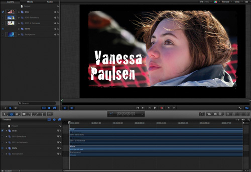
This project contains several layers organized into groups. It is similar to projects you worked with in earlier lessons but some important differences make it more effective for setup as a 3D scene. To see all the layers in the Layers list without scrolling, you can resize the layers.
2. In the Layers list, open all the groups. Click the Scale button, and then drag the slider to the left, shrinking the size of each layer in the list, until you can see them all.
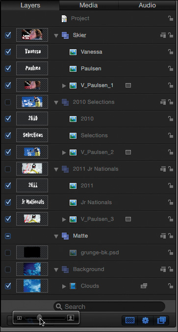
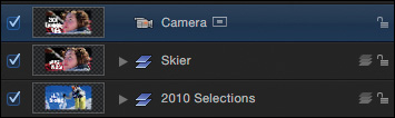
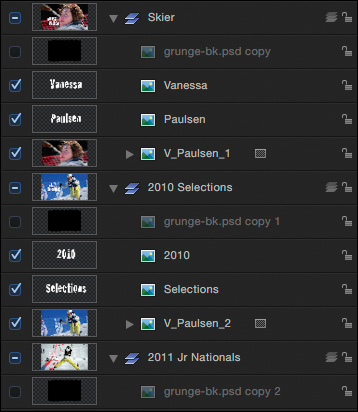
In this project, you’ll find groups that profile a skier and the events in which she has competed. Each group contains the title graphic and a photo from an event. This arrangement allows you to treat each image/text combination as a “set” made up of layers you can move and rotate individually, and then move and rotate together by transforming the group that contains them.
The 2010 Selections and 2011 Jr Nationals groups are turned off, so you see only the Skier group in the Canvas.
Each photo has an image mask applied, and all three image masks use the same source to create the mask: the grunge-bk.psd layer in the Matte group.
The last group contains the background video clip and is currently turned off so that you can focus on the other groups.
Although you’ve learned that layers typically start at different points in the project, all layers in this project start on the first frame of the project. This setup will come in handy when you arrange the layers and groups in 3D space, because you’ll be able to see them all without moving the playhead.
3. Save the project to the Lesson_13 > Student_Saves folder.
Now that you understand the structure of the project, you can create depth in the scene by moving and rotating the layers in 3D space.
4. In the Skier group, select the Vanessa text/graphic layer, and press F1 to open the Properties pane of the Inspector.
The Inspector Transform parameters can position a layer up and down on the y-axis or side-to-side along the x-axis. They can also rotate a layer on the z-axis, like a propeller. But they can do a lot more.
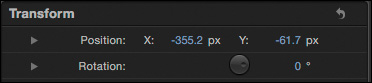
5. For both the Position and Rotation properties, click the disclosure triangle next to the name to open additional parameters for each property.
When opened, the position parameters include Z-position, and the Rotation parameters include X and Y Rotation to allow full 3D transforms for each layer.
6. Drag in the value fields that appear to see how these values affect the layer. Undo after each change.
You may have noticed that subtracting values from the X position moves an object to the left, and adding to the X value moves an object to the right. Adding to the Y value moves an object up, and subtracting from the Y value moves an object down. You can move an object closer by adding to the Z value, or move it farther away by subtracting from the Z value. The center of the Canvas has coordinates as X=0, Y=0, Z=0, making it very easy to center objects by entering the zero values in the Inspector.
You can also make these 3D changes in the HUD and directly in the Canvas. To do so, you use a special tool.
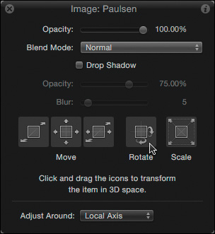
7. Open the HUD, and in the toolbar, choose the Adjust 3D Transform tool, or press Q.
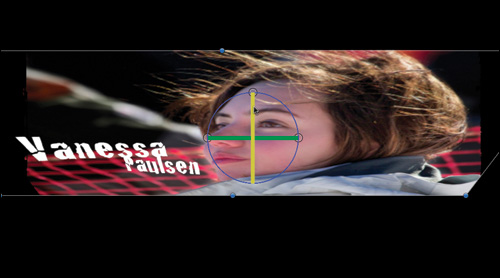
The HUD populates with the 3D Transform tools, and the center of the selected layer in the Canvas now contains three colored arrows and three hollow white circles.
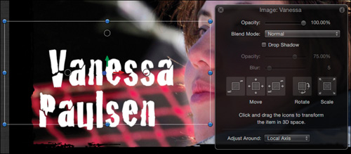
8. Drag left on the leftmost Move control in the HUD, to bring the Vanessa text/graphic layer forward (toward you) along the z-axis. Keep your eye on the Inspector to set a value of about 200 pixels.
9. In the HUD, drag in the middle Move control to slide the layer up and over to the right a little, again watching the Inspector to see exactly which parameters are changing.
The right Move control in the HUD moves the selected layer along either the x-axis or z-axis, but you don’t need it here. This control is useful when you want to spread layers in space and keep them all on the same horizontal plane, like actors on a stage.
10. In the HUD, try dragging in the Rotate control, watching both the Canvas and the Inspector. The layer rotates along the x, y, and z axes, but in this exercise you just want to swing the layer on its y-axis. Press Command-Z to undo the changes.
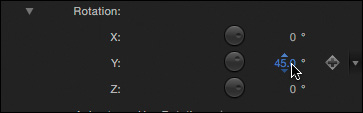
11. In the Inspector, drag right on the Rotate control to set the Y Rotation value to 45 degrees.
You can make these same types of 3D transformations directly in the Canvas with the Adjust 3D Transform tool. Let’s position and rotate the Paulsen text/graphic layer to offset it from the Vanessa layer.
12. In the Layers list, select the Paulsen text/graphic layer.
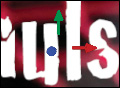
As you learned when adjusting the mountain gorilla text in Lesson 6, the colors of the three axis arrows—red, green, and blue, or RGB—map to the three axes of 3D space. The red arrow moves along the x, or horizontal, axis; the green arrow moves along the y, or vertical, axis; and the blue arrow moves along the z, or depth, axis. The blue arrow is pointing almost directly at you, so it looks more like a dot than an arrow.
You can drag an arrow to constrain movement to that axis alone.
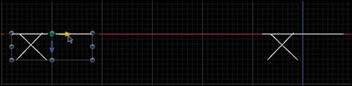
13. Drag the blue arrow to the right and watch the Inspector to move the layer about 200 pixels forward along the z-axis. The selected arrow turns yellow. Notice that the status bar at the top of the Canvas displays the transform values and matches what is shown in the Inspector.
14. Drag the red arrow to the right to move this layer up against the side of Paulsen’s face, and then drag the green arrow up to move the text layers closer together.

You can also drag anywhere inside the bounding box to move along both x and y axes at the same time.
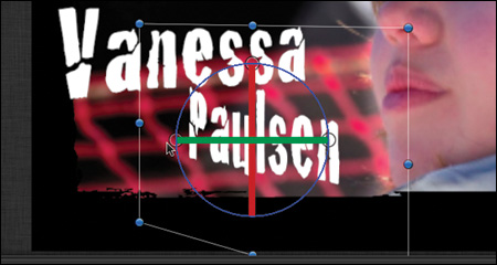
The hollow white circles at the 12, 3, and 9 o’clock positions are rotation handles.
15. Drag the y-axis rotation handle (at 9 o’clock) to the left to rotate the layer –45 degrees around the y-axis. Colored rotation bands appear to indicate the axis of rotation.
Layers and groups rotate around their anchor points. Therefore, changing the location of the anchor point can have a dramatic impact on the rotation. For example, to swing a graphic of a door from the edge rather than from its center, you would move the anchor point to that edge.
You can see how easy it is to change the position and rotation of layers in 3D space using the Inspector, the HUD, and the Canvas. One more crucial step remains for making layers behave as though they live in a 3D world: converting the groups that contain them into 3D groups.
Converting 2D Groups to 3D
Layers only interact or intersect with each other—and respond to cameras or lights—when they are contained inside 3D groups. Fortunately, it’s quite easy to switch a group from 2D to 3D.
Before you do so, however, you will work with the various axis modes in the HUD and Canvas. They can be handy when manipulating layers and groups.
Let’s say you want to push the Paulsen text/graphic layer straight back in z-space, to move it behind the photo.
1. In the HUD, drag left and right on the left Move control, and then undo the change.
2. In the Canvas, drag left and right on the blue z-axis arrow, and then undo the change.
Notice that in both cases the layer does not move straight toward you or away from you. Rather, it moves along the layer’s own z-axis, which is perpendicular to the surface of the layer.
3. In the HUD, drag around in the Rotate control, and then undo the change.
Notice in the Canvas that the colored arrows move as the layer moves: The red arrow stays horizontal with respect to the layer, the green arrow stays vertical with respect to the layer, and the blue arrow always points straight out from the plane of the layer. This is called Local Axis mode since you are adjusting the layer around its own, local set of axes.
4. In the HUD, from the Adjust Around pop-up menu, choose View Axis. In the Canvas, the blue arrow now points directly at you, even though the layer is rotated.

5. In the HUD, once again drag around in the Rotate control, watch the results, and then undo the change. This time, no matter how the layer moves, the axes remain fixed: Red is always horizontal, green is always vertical, and blue is always pointing straight out—with respect to the computer screen, or your view of the project.

The other option, World Axis, is currently the same as View Axis. That will change after you add a camera and begin to move in 3D space. The Inspector’s Position and Rotation values are always based on the World Axis.
This axis mode makes it easier to push the layer directly away from you.
6. In the HUD, drag the left Move control to the right; or, in the Canvas, drag the blue arrow to the left to move the Paulsen text layer back in z-space to about –15 pixels.
Setting the Adjust Around pop-up menu to anything other than Local Axis on a 2D group will prevent you from adjusting the Z position of an object directly in the Canvas. You can, however, adjust the Z position using the HUD or Inspector.
The V_Paulsen_1 layer is located at 0 pixels along the z-axis (you can select it and check that value in the Inspector), so the Paulsen text/graphic layer should be at least partially behind the photo now, but it still appears completely in front. This is because you are working in a 2D group, and layers in 2D groups do not interact with each other.
The compositing order of 2D group layers in the Canvas is dictated entirely by the layer order in the Layers list. Because the Paulsen text layer is above the V_Paulsen_1 photo layer in the Layers list, it will always appear in front of the photo in the Canvas. How layers are positioned in front of and behind other layers is the fundamental difference between a 2D group and a 3D group.
Another way to see that the layers aren’t yet truly 3D is to rotate the group.
7. Select the Skier group, and then in the Canvas, drag the top rotation handle down to tilt the group around its x-axis.
All the layers appear completely flat, and the mask doesn’t tilt with the layers. To make layers interact with each other based on their positions in z-space rather than their layer order, you need to switch the group containing them to 3D.
9. In the Group pane of the Inspector, set the Type pop-up menu to 3D.
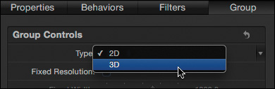
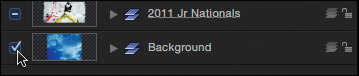
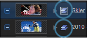
When the group type is changed to 3D, the icon to the left of the Layers list for that group changes from three flat rectangles to a stack of rectangles to indicate that it is now a 3D group. Notice the difference between the 3D icon and the icon on the 2010 Selections group below it in the Layers list.
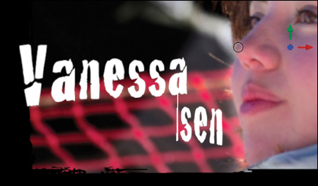
In the Canvas, the Paulsen text now intersects with the photo layer.
Let’s return it to its previous location.
10. Use the HUD or Canvas to move the Paulsen text forward to about 200 pixels along the z-axis.
11. Once again, rotate the group down around the x-axis. The layers remain rotated and spread out in z-space when you look at them from a different angle.

You are finished building your first scene. You will use these same tools to arrange the other two scenes in a similar fashion.
12. Now that you’re a bit more familiar with the tool, undo the group rotation, and turn off the Skier group.
13. Turn on the 2010 Selections group and make it a 3D group.
You can also make a selected 2D group into a 3D group by clicking the 2D/3D icon in the Layers list, or choosing Object > 3D Group, or pressing Control-D.
To make sure these text graphics have the same rotations and z-positions as the ones in the first set, you can copy the values from the layers in the Skier group.
14. Select the Vanessa text/graphic layer. You want to start the 2010 text/graphic layer with the same position and rotation as the Vanessa layer.
15. Drag the word Transform from the Properties pane onto the 2010 layer in the Layers list.

The 2010 text layer takes on all the values from the Transform group of parameters. It is now about 200 pixels forward in z-space and rotated 45 degrees on the y-axis. Let’s do the same for the Selections text layer.
16. Select the Paulsen layer, and drag the word Transform to the Selections layer.
With both graphics layers properly positioned and rotated with respect to each other, you only need to reposition them with respect to the photo.
17. Shift-click both the 2010 and Selections text layers to select them, and in the Canvas, drag them up so they are more fully centered with the skier in the photo. Now you just need to repeat the same process on the last set.

18. Turn off the 2010 Selections group; then turn on the 2011 Jr Nationals group and make it 3D. Drag the Transform properties from the 2010 text layer to the 2011 text layer and from Selections to Jr Nationals, and then reposition the layers as necessary. Save your work.

Terrific! Your 3D “sets” are now built. The next step is to spread them out in 3D space. For that task, it’s very helpful to have a camera in the project.
Adding and Working with Cameras
A 3D environment without a camera is like a fast car without the keys. You can sit in it and look around, but you can’t go anywhere.
In 3D mode, everything that you see in the Canvas represents the viewpoint of a camera, either the default reference cameras that view the scene from specific positions and orientations such as top, right side, and front; or a scene camera that you add to look at your scene from different points of view.
When you add a camera to a Motion project, a whole set of new tools, or 3D overlays, become available. You can use these tools to manipulate the scene camera or to step away from the camera to get a different perspective on your 3D scene. You can even separate your view from the camera and rise above to get a bird’s-eye view as you build your scene.
If you don’t have any 3D groups in your project, adding a camera will automatically switch all your groups to 3D. Let’s try it.
1. Close all the groups in the Layers list. You don’t need to see the individual layers for the next steps.
2. Command-click each of the three 3D groups to select them, and then press Control-D to revert them to 2D groups.
3. In the toolbar, click the New Camera button or choose Object > New Camera. A dialog appears, warning you that cameras affect only 3D groups.

4. Click “Switch to 3D.”

• All the groups in the project are automatically switched to 3D.
• A new Camera layer appears at the top of the Layers list.
• The HUD transform controls now affect the camera.
• New tools appear in three corners of the Canvas.
These five new 3D overlays are available only when a camera is in the scene. You can choose specific 3D overlays to turn on or off, and you can toggle the visibility of all the 3D overlays.
5. In the upper right of the Canvas, click the “View and Overlay” pop-up menu.
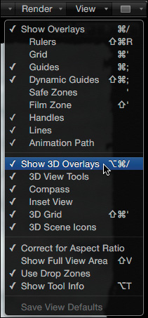
The five 3D overlays are listed underneath the Show 3D Overlays command. The Inset view and 3D grid are not visible in the Canvas because they appear only under certain conditions.
If you do not see checkmarks next to Show 3D Overlays and every 3D overlay, choose each one until all 3D overlays are turned on.
By default, when you add a camera, you begin viewing the scene through the camera, as indicated by the words Active Camera at the top left of the Canvas. The camera is added and positioned so that your view of the scene does not change when you switch from 2D to 3D. Now that you have a camera, you can move it around.
6. In the HUD, use the 3D transform tools to move and rotate the camera. Notice that the changes are also made in the Properties Inspector. Undo after each change.
When you move the camera up and down or rotate it, a 3D grid appears in the Canvas. The grid represents the “floor” of the virtual world, with a red x-axis and a blue z-axis intersecting at 0, 0, 0—your virtual “home base.” This grid can help you stay oriented as you move around in 3D space.
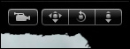
At the top right of the Canvas is a set of three icons with a camera icon to the left. The three icons are the 3D View tools—Pan, Orbit, and Dolly. The camera icon next to them indicates that these tools are manipulating the camera just as you did when using the HUD.
If you can use the HUD to manipulate the camera, why would you need the 3D View tools? In the HUD, the camera can be manipulated only if it is the selected layer. Often, a different layer or group will be selected because you are working on it (transforming it, animating it, or adding effects) and you want to move the camera to change your view of the scene. The 3D View tools allow you to move and rotate the camera even when the camera layer is not selected.
7. Drag the Pan, Orbit, and Dolly tools to see how they work. Notice the changes reflected in the Inspector. This time, do not undo your changes.
These tools include a handy feature to quickly reset the camera.
8. Double-click any one of the 3D View tools and look at the Inspector.
Double-clicking a 3D View tool resets the camera to 0, 0, 0 for both Position and Rotation, so it is once again looking at the center of your virtual world. Like Dorothy clicking the heels of her ruby slippers, no matter how far afield you may stray in 3D space, you can always come home with a simple double-click.
But what does it mean when the camera is at 0, 0, 0? You know the photo layer is at 0, 0, 0, so doesn’t the camera have to back up a distance from the very center of the z-axis to “look at” the photo and have it fill the screen?
To understand where the camera is in relationship to the layers in your scene, you need to step away from the camera, or even fly above it. And that’s the purpose of the 3D overlay at the bottom left of the Canvas, the 3D Compass.
9. Move your pointer over the arrows around the 3D Compass but don’t press the mouse button. The arrow under the mouse lights up, and text appears, identifying the name of the view Motion will display if you click that part of the 3D Compass.
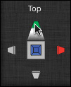
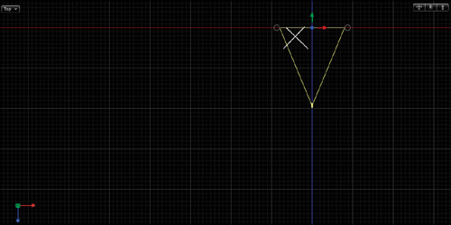
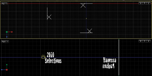
10. Click the top of the green arrow to go to the Top view. The scene rotates as you “fly” above it. You are now looking straight down the world’s y-axis.
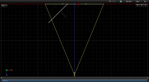
Layers in Motion are always 2D—like playing cards—which is why the two rotated graphics layers look like a white X in the Canvas. You can’t see a line for the photo layer because it aligns with the focal plane of the camera as represented by the base of the yellow isosceles triangle.
The red, green, and blue arrows are located at the center of the focal plane, which is why the camera’s location is 0, 0, 0. In other words, the position of the camera is determined by its focal plane, not by its “body.”
11. In the HUD, drag the Rotate control.
Notice that the camera rotates around the center of its focal plane. No matter how much you rotate the camera, it stays focused on the center of your virtual world. This behavior will come in handy when you animate your camera in the next lesson.
Notice also that a small window appears at the bottom right, the Inset view. It shows you how the scene looks from the camera’s point of view—so you can adjust the camera from a different view, and still see the results from the camera’s view.
You may wonder why the axes’ arrow colors for the camera don’t match the grid colors: The green arrow lines up with the blue grid line. If you look in the HUD, you can see that you are in View Axis mode—the mode in which z (blue) always points straight at you.
12. Undo the camera rotation, and then, in the HUD, change the View Axis to World Axis. The axes of the camera and the 3D grid now match.
Look at the 3D View tools at the top right of the Canvas. Now that you are not in the Active Camera view, the camera icon no longer appears next to these tools. Therefore, these tools can be used in Perspective view to pan, orbit, and dolly without moving the camera.
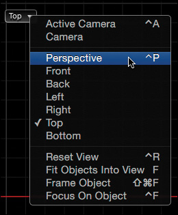
Let’s select a more freeform view than the Top view and use the 3D view tools to move around. In addition to the Compass, you have another way to change your 3D view. The Camera pop-up menu at the top left of the Canvas displays the current view with a checkmark and allows you to change the view.
13. From the Camera pop-up menu, choose Perspective, and then use the 3D View tools to pan, orbit, and dolly the view.
Notice that the camera has not moved, and neither have any of the layers. You have changed only your view of the scene by using one of the default reference cameras.
14. From the Camera menu, choose Reset View to return to your perspective view starting point.

To go to the view looking through the camera, you use the Camera menu.
15. From the Camera menu, choose Active Camera, or press Control-A. Your view returns to the original camera view.
Now that you know how to turn on and use the 3D overlays to change your view of the scene and to manipulate the camera, you can arrange the groups in 3D space.
Arranging and Modifying Groups and Layers in 3D Space
In the next lesson, we will animate the camera to fly from one set to the next. But right now, all the groups are located at the same place: the center of the virtual world. So you’ll spread them apart, and rotate them so that the camera must twist and turn as it moves from one group to the next.
To move groups in 3D space, you can use the 3D overlays and the Adjust 3D Transform tool. To see the impact of your changes from more than one angle, we’ll use a view layout to display two angles in the Canvas.
After you spread out the groups and layers in 3D space, you may still need to do some work on them—transforming layers, and adding masks, filters, or behaviors. The Frame Object command will help you quickly find and modify elements. Finally, you will use a 2D group to add a background that stays put, no matter where the camera moves.
Arranging the Groups
The first task is to move two of the groups away from the camera and then rotate them to face it. Facing the camera isn’t required, but it can create a pleasing arrangement that makes it easy for the camera to turn and see each group.
1. In the Layers list, select the activation checkboxes of the Skier and 2010 Selections layers so that you can see them as you move them in 3D space.
The groups of layers are currently stacked on top of each other. To spread them apart, use different views to get a broader perspective.
2. In the HUD, set Adjust Around to Local Axis so you can move and rotate the groups more in line with the camera’s view.
3. Click the 3D Compass to go to the Top view; then in the 3D View tools use the Dolly and Pan controls to move the camera and set icons to the upper right of the Canvas.
We’ll leave the Skier group in front of the camera, move the 2010 Selections group to the left and down, and move the 2011 Jr Nationals group directly behind the camera.
4. In the Layers list, select the 2010 Selections group, and in the Canvas, drag the red x-axis arrow to the left, using the status bar as a guide to move the group about –4000 pixels.
5. Drag the blue z-axis arrow down to move the group to about 1000 pixels, until it is roughly even with the camera.
6. In the Inspector, in the Y-Rotate field, type 90 to rotate the set counterclockwise and face the camera.

Locating the rotation handles in this view can be a little difficult, although you’re welcome to try.
The 2011 Selections group is now off-camera to the left, and facing the camera; so if the camera turned to look, it would see the elements of the group face-on.
Let’s now move and rotate the 2011 Jr Nationals group. To keep the Inset view from getting in the way, you will turn it off.
7. From the “View and Overlay” pop-up menu, choose Inset View to deactivate it.
8. Select the 2011 Jr Nationals group. Drag the blue arrow down to move the group to about 3000 pixels; then in the Inspector rotate the group to 180 degrees in the Y direction to face the camera. This is your preliminary set arrangement. You can adjust it as you want, after you see how it looks with the camera animation.

Now, you want to see what these groups look like from “ground level,” but you want to keep this view onscreen as well, in case you want to use it to make changes.
You can display your scene from multiple angles simultaneously by choosing one of several view layouts. Each layout divides the Canvas into viewports. Each viewport can display the scene from a different position and orientation. You can display viewports by selecting the Active camera or one of the default reference cameras from the Camera menu.
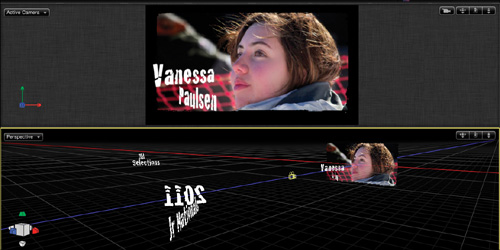
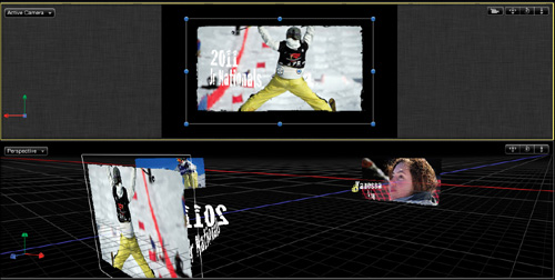
9. At the upper right of the Canvas, from the View Layouts pop-up menu, choose the split horizontal view—the third option.
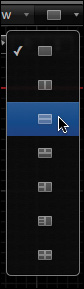
The Canvas splits into two viewports of the scene. The upper viewport shows the Top view you were working in, and it has a yellow border around it to indicate that it is the active view. The lower viewport shows the Right view by default, but you can change either viewport to whichever view you want.
The active viewport is the one that animates during playback. You can make a viewport active by clicking inside it.
10. Use the Camera menu to set the upper viewport to the Active Camera view. Then press Shift-Z to fit the set in the viewport.
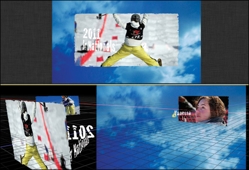
11. In the lower viewport, click the center of the 3D Compass to go to the Perspective view, and then use the 3D View tools to pan, orbit, and dolly the view until you can see all three sets in the viewport.
The text graphics for the sets you positioned and rotated are visible, but the photos are not. This is because all three photos are masked by the same graphic in the Matte group, and the graphic is still located at 0, 0, 0. So, it masks the Skier layer, but it’s no longer aligned with the other two photo layers since you repositioned and rotated them.
To align the masks, we want a separate copy of the graphic to mask each photo layer, and we’ll move each copy to the exact same location as each photo layer.
Modifying Layers in 3D Space
In this exercise, we will create copies of the graphic that was used as a mask and copy it to each of the three skiing photo groups. Then each copy will be aligned with the photo layer in that group. While you could drag the layers in the different Canvas windows to align them, there is a much faster way to move a layer to a precise location in 3D space.
1. Open the Matte group. Option-drag a copy of the grunge-bk.psd layer, first to the Skier group, and then the Selections group, and finally to the Nationals group. After it is copied to each of the three groups you’ve been working with, delete the Matte group.
The groups open, and a copy of the graphic is now located in the top layer of each group. In the lower viewport of the Canvas, all the photos appear without masks.
To move each grunge graphic layer to the same position and rotation of each photo, let’s copy the parameters from the photo to the matte graphic.
2. In the Skier group, select and activate the grunge-bk.psd copy layer and look at the Properties pane of the Inspector. In the Perspective view, the layer is clearly in the wrong position; in the Inspector, you can see that it’s nowhere close to 0, 0, 0—the location of the V_Paulsen_1 photo.
You could click the Transform properties reset arrow to return the layer to 0, 0, 0 for both position and rotation, but that would also reset the scale, which you don’t want to do. Besides, that approach won’t work if the layer you want to match the graphic to isn’t at 0, 0, 0.
3. Select the V_Paulsen_1 photo layer.
4. In the Properties pane, Shift-click the words Position and Rotation to select them both, and then drag them onto the grunge-bk.psd copy layer. The Position and Rotation values are copied to the graphic, and in the Active Camera view it lines up with the photo. Now you just need to apply it as the source for the image mask.

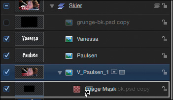
5. Open the V_Paulsen_1 photo layer to reveal the image mask, and then drag the grunge-bk.psd copy layer onto the Image Mask. The photo in the Active Camera view is now properly masked by the graphic.
You can set the source of the image mask in three locations: by selecting the image mask, and then dragging the source layer to the well in the HUD; by dragging directly to the image mask in the Layers list; and by dragging into the Mask Source well in the Inspector.
This process of dragging parameters from the Inspector to a layer can be used to move any layer to align with any other layer in 3D space. It’s quite powerful, and we’ll use it again for the 2010 Selections group. However, this group is a bit difficult to see in the Perspective view. It’s on an angle and far away. You could use the 3D View tools to move closer, but there’s a faster way to move the camera to frame any group or layer in 3D space.
6. Close the Skier group, and select the V_Paulsen_2 photo layer inside the 2010 Selection group.
7. In the upper viewport, from the Camera menu, choose Frame Object. The Active camera rotates to face the selected layer, and pans and dollies until its focal plane touches the layer, thereby framing the layer.

This command changes the position and orientation of the camera itself—not just a view—so be cautious when using it if the camera is already in a specific location you want to preserve, or if you have already animated the camera with behaviors or keyframes. In this case, the starting position of the camera is 0, 0, 0, so it’s very easy to return “home” by double-clicking one of the 3D View tools or resetting the camera’s Transform parameters in the Properties pane.
8. In the Properties pane, Shift-click the Position and Rotation parameters, and drag them inside the 2010 Selections group onto the grunge-bk.psd copy 1 layer.
The position and rotation of the V_Paulsen_2 photo layer is 0, 0, 0—even though the layer isn’t close to the center of the virtual world. This is because the coordinates are relative to the group containing the layer. Although you moved the entire group and changed its position and rotation, you haven’t changed the position or rotation of this layer with respect to the group that contains it.
9. Open the V_Paulsen_2 photo layer, and drag the grunge-bk.psd copy 1 layer onto the image mask. The photo now appears masked in the Active Camera view. There’s just one more group to go.

10. Close the 2010 Selections group, select the V_Paulsen_3 photo layer in the 2011 Jr Nationals group, and choose Frame Object from the Camera menu or press Command-Shift-F to frame the layer with the camera.
11. In the Properties pane, Shift-click the Position and Rotation parameters, and drag them inside the 2011 Jr Nationals group onto the grunge-bk.psd copy 2 layer.
12. Open the V_Paulsen_3 photo layer, and drag the grunge-bk.psd copy 2 layer onto the image mask.
All three photos now appear properly masked. To finish setting up the 3D scene, let’s add a background.
Mixing 2D and 3D Groups
Motion lets you freely mix 2D and 3D groups in a 3D project. Because 2D groups aren’t affected by the camera, you can use them to add elements that you always want to see, such as a watermark, station ID, or background element.
1. Close the 2011 Jr Nationals group and turn on the visibility of the Background group.
In the Active Camera view, nothing changes where the camera is framing the 2011 Jr Nationals group. But in the Perspective view, the background clouds appear behind the Skier group.

Because the Background group is a 3D group, the camera sees it in 3D space at a fixed location. But you want to see the background no matter where the camera moves.
2. Click the 2D/3D icon for the Background group to switch it to a 2D group. Now the Clouds video appears in the upper Active Camera window behind the Jr Nationals group, and also appears in the Perspective view, flat to the screen.
3. Try orbiting the camera with the 3D View tool in the Active Camera view.
No matter where the camera looks, the Clouds video stays still and always faces the viewer. However, you can still manipulate the position and rotation of 2D groups and their layers.
4. In the upper Active Camera window, double-click one of the 3D View tools to reset the camera to its default location at 0, 0, 0, framing the Skier group.
5. Open the Background group and select the Clouds layer.
6. Look to the left of the toolbar. If the Adjust 3D Transform tool is not selected, press Q to select it.
7. In the HUD, drag in the Move, Rotate, and Scale controls to transform the layer. After each adjustment, press Command-Z to undo it.
The layer moves and rotates in the Active Camera and Perspective views, which means you can position and rotate a layer in a 2D group as needed to set it up, but it won’t move from that orientation when the camera moves.
Notice that no matter how far forward you move the layer along the z-axis, it never moves in front of the other groups. This is because 2D groups respect the layer order in the Layers list.
8. Close the Background group, select it, and choose Object > Bring to Front. The cloud now obscures all other groups because it’s a 2D group at the top of the layer stack. If this group contained a small semitransparent watermark, corporate logo, or station ID in the corner of the screen, it would stay there as the camera moved.
9. Choose Object > Send to Back to return the Background group to the bottom of the layer stack and the back of the composition.
10. Save the project.
Throughout the lessons in this book, you’ve learned that creating 2D and 3D groups is a powerful compositing technique. It’s more than just dropping layers into a “folder” for organization. That being said, with that power comes a few caveats. The most important caveat being rasterizing, also sometimes called pre-composing, which you’ll examine in the next section.
Rasterizing Groups
Rasterization happens on both 2D and 3D groups when certain filters, masks, or blend modes are applied to a group. The result of rasterization is that the group is converted into a bitmap image, and that conversion impacts how groups interact with other project elements.
In this exercise, you’ll discover the ways that rasterization is imposed on your group and how to identify rasterized groups.
1. At the upper right of the Canvas, from the View Layouts pop-up menu, choose the single view, the first option. Then press Shift-Z to fill the window.
2. In the Layers list, select the Skier group, and in the Inspector, set Blend Mode to Normal.
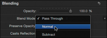
You just applied the quickest way to rasterize a group. Any time you change a 2D or 3D group’s Blend Mode setting to anything other than Pass Through, the group is rasterized. It may not appear any different in the Canvas right now, but you can see indications that the group is rasterized.
Look at the icons to the left of the names of the Skier and 2010 Selections groups, and notice how they differ.
You’ll also see a small R icon next to the Blend Mode menu in the Inspector.
3. In the Inspector, return the Skier group’s Blend Mode to Pass Through.
Now the icons look the same. Pass Through means that any blend modes applied to layers within a group will pass through to the groups beneath them.
4. Open the Skier group and select the Vanessa layer. In the HUD, set Blend Mode to Overlay to blend it with the photo layer and a bit with the clouds background.

Because the blend mode for the group containing this layer is set to Pass Through, the Overlay blend mode on the Vanessa layer passes through to the Clouds layer in the Background group beneath it. This is the default state for groups and blend modes.
However, certain operations applied to a group will cause that group to become rasterized—converted into a bitmap image—before it is composited with other groups. When a group is rasterized, any blend modes applied to layers within it will no longer pass through to the groups below.
5. Select the Skiers group, and in the Inspector, drag the slider to lower the Blending Opacity value.
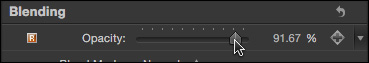
The instant you change the Blending Opacity value from 100% a box surrounds the Skier group icon to indicate that the group is rasterized. The Overlay blend mode applied to the Vanessa text no longer affects the group underneath. The text is now white where it should be composited over the clouds background.
Certain operations applied to a group will trigger rasterization and, as a result, blend modes on layers in that group will not pass through to layers in the groups below.
There’s often another way to accomplish the same result. In this example, you could change the opacity of each individual layer in the group rather than alter the group itself. However, for this project, no blend mode or opacity is needed.
6. Select the Vanessa layer. In the HUD, return Blend Mode to Normal, and then return the Skier group Opacity to 100%. Close the group, and save your work.
The text returns to the standard white color it had prior to changing its blend mode to Overlay.
The most common operations that trigger rasterization for a group include adding a mask, applying a filter, and changing blend modes or blending opacity at the group level. The Motion documentation’s groups and rasterization chapter includes a list of all operations that trigger rasterization.
You now know about rasterization, how to use 3D overlays, manipulate a camera, arrange objects in 3D space, animate with camera behaviors, and mix 2D and 3D groups. Your scene is arranged, and you are ready to animate the camera.
Lesson Review
1. How can you automatically switch all groups in your project to 3D?
2. How do you add a camera?
3. Name three locations in which you can change the position and rotation of a layer or group in 3D space.
4. What’s the difference between layers in a 2D group and in a 3D group?
5. Do the 3D View tools always control the camera?
6. Which tool is used to make 3D transformations directly in the Canvas, and which keyboard shortcut selects it?
7. How can you quickly move a camera to look at and frame a specific layer in 3D space?
8. In the HUD, how would you set the Adjust Around pop-up menu if you wanted the z-axis of a layer to always point straight at you, no matter how the layer or the camera was oriented?
9. If you applied an image mask to a layer that is positioned in 3D space, why wouldn’t the image mask appear on the layer?
Answers
1. By adding a camera
2. In the toolbar, click the New Camera button, or choose Object > New Camera.
3. In the Inspector, the HUD, or the Canvas
4. Layers in 2D groups are not affected by the camera, and are composited based on stacking order in the Layers list.
5. No. The 3D View tools control the camera only when the window is set to a Camera view.
6. The Adjust 3D Transform tool allows you to transform the position and rotation of layers and groups in both the HUD and the Canvas. Press Q to select the Adjust 3D Transform tool.
7. Select the layer, and from the Camera menu, choose Frame Object, or press Shift-Command-F.
8. Set the Adjust Around pop-up menu to View Axis mode to orient the axes so that they reflect the orientation of your computer screen.
9. The image mask source is not aligned to the layer you are masking.
Keyboard Shortcuts