Nuclear Power Generation
Abstract
In this chapter nuclear power generation systems are introduced. In the first part of the chapter the basic theory of nuclear reaction is reviewed as a prerequisite for understanding nuclear fuels and controlled generation of nuclear heat. Conventional and advanced concepts for nuclear fuel are then studied. All types of conventional reactors for nuclear power stations and advanced generation reactors are introduced.
As cogeneration represents a major development trend for nuclear power generators, a section of this chapter is dedicated to cogeneration schemes of power and district heating, power and high-temperature process heat, power and desalination, and power and hydrogen generation. The chapter includes several illustrative examples and case studies.
Nomenclature
A atomic mass (AMU)
c speed of light (m/s)
E energy (J)
ΔEb binding energy (MeV)
e specific energy (J/kg)
ex specific energy (J/kg)
N number of neutrons
N number of atoms or particle density
q heat amount per unit of mass (J/kg)
R radius, m
r radial coordinate, m
T temperature, K
t time, s
Z number of protons
Greek letters
α transfer coefficient
η energy efficiency
ψ exergy efficiency
λ excess air
ε dissipation parameter
σ cross-section, cm2
ϕ radiation particle flux
Subscripts
0 exchange current; reference state
act activation
aux auxiliary
c compressor
conc concentration
eq equilibrium
f fuel
fc fuel cell
H heat source
L limiting
ng natural gas
oc open circuit
p pump
PG power generation
rev reversible
s steam
t turbine
TC thermochemical
tot total
Superscripts
0 reversible
ch chemical
thrm thermomechanical
6.1 Introduction
Nuclear power stations are used in thirty-one countries or 15% of the total number of countries in the world. Moreover, the generated nuclear power covers 13% of world energy consumption (WNA, 2013), which represents ~ 2.5 PW. Currently, the most nuclear power is generated in the United States with a 31.3% share, followed by France with a 16.8% share; some other countries with an important share of nuclear power generation are the Russian Federation (6.4%), Japan (6.2%), South Korea (5.8%), Germany (4%), Canada (3.5%), Ukraine (3.4%), and China (3.3%).
All nuclear power stations worldwide use uranium as nuclear fuel extracted from uranite mineral resources. The richest country in uranite is Australia, with a 23% share, followed by Kazakhstan with 15%, Russia with 10%, South Africa and Canada with 8%, United States of America with 6%, Brazil, Namibia, and Niger with 5%, Ukraine with 4%, Jordan and Uzbekistan with 2%, and India with 1%.
In a nuclear power station a controlled nuclear reaction is maintained in the reactor. The nuclear reaction generates mainly neutron radiation that is immediately converted to high-temperature heat. A steam generator with special design—depending on the reactor type—is then used to extract the thermal energy produced by the reaction and to obtain pressurized superheated steam at 525–625 K. The steam generator is part of a steam Rankine power plant which produces power with a typical energy efficiency of 30%.
The key to achieving the current level of technology of nuclear power stations has been the establishment of a new body of science in the last quarter of the nineteenth and the first quarter of the twentieth centuries: nuclear physics. The first laboratory demonstration proving the possibility of generating nuclear radiation in a controlled manner was realized in 1924 by the research group of the well-known scientists Frederic and Irene Joliot Curie in Paris and their PhD student Stefania Maracineanu, which showed that lead, being activated with radioactive polonium, starts emitting radiation (Neues Wiener Journal, 1934). Further experiments of the research group led to the formulation of a theoretical model for artificial radioactivity in aluminum bombarded with alpha particles, a discovery which was of utmost importance for the progress of nuclear energy engineering; this discovery was acknowledged by the 1935 Nobel Prize for chemistry awarded to Frederic and Irene Joliot Curie.
The proof of the concept for a nuclear reactor was achieved only 7 years later in Chicago by Enrico Fermi, who demonstrated the first nuclear reactor with a controlled chained fission reaction of uranium. Later a nuclear reactor of 1 MW was built and tested at Oak Ridge Laboratories (1943) and the first large-size nuclear reactor (of 250 MW installed capacity), called the B reactor, began to operate near Richland Village, WA (1944). The first nuclear power plant was commissioned in Idaho, USA, in 1951, with an installed electricity of 100 kW. CANada Deuterium Uranium (CANDU) technology achieved a commercial level in 1962. During the last 40 years, many kinds of nuclear reactors have been developed for the purpose of electric power production and marine and space mission applications.
Nuclear power generation is a crucial player in the generation of wealth, economic development, and energy security. In this chapter, nuclear power generation is discussed starting from the most basic concepts of nuclear reaction, to the engineering of controlled generation of nuclear heat and power cycles, to the advanced concepts of a nuclear reactor. As cogeneration brings a better recognition and wider acceptance of nuclear energy for daily applications in various sectors, this topic is also discussed, with emphasis on producing district heating, process heat, potable water from desalination, hydrogen, and other synthetic fuels.
6.2 Nuclear Reactions
It is well known that some chemical elements are radioactive; they can transform themselves into other chemical elements and emit or absorb radiation through nuclear processes such as radioactive decay, or they can participate in fusion or fission reactions. How do nuclear reactions occur and how can they be controlled for steady generation of high-temperature heat? This is the main question that we want to answer in this chapter, by providing the basic elements of nuclear energy and power generation applications.
Let us recall that the atom is the smallest unit of a chemical element (radius of about 1 ![]() ) and that there are 118 known atoms corresponding exactly to the periodic table of elements. The atom is made up of a nucleus and a number of electrons. The nucleus is formed of protons and neutrons. In normal condition the atom is neutral with respect to electric charge; thus, the number of electrons is the same as the number of protons. The nucleus cannot be broken down by chemical reactions, but it can be affected in its constituency by nuclear reactions. Table 6.1 gives the formal definition of the elementary particles which are considered the most significant ones for nuclear power generation.
) and that there are 118 known atoms corresponding exactly to the periodic table of elements. The atom is made up of a nucleus and a number of electrons. The nucleus is formed of protons and neutrons. In normal condition the atom is neutral with respect to electric charge; thus, the number of electrons is the same as the number of protons. The nucleus cannot be broken down by chemical reactions, but it can be affected in its constituency by nuclear reactions. Table 6.1 gives the formal definition of the elementary particles which are considered the most significant ones for nuclear power generation.
Table 6.1
A List of Significant Particles in Nuclear Physics
| Particle | Symbol | Definition |
| Electron | e− | Subatomic particle having one negative elementary electric charge and a very small rest mass, negligible with respect to the nucleus mass |
| Positron | e+ | The antimatter that annihilates an electron having the same rest mass but positive charge |
| Proton | p+ | Subatomic particle having one positive elementary electric charge and rest mass. Proton is categorized as a nuclide because it enters into the constituency of the atomic nucleus |
| Neutron | n | Subatomic particle having no electric charge and a rest mass approximately equal to that of proton. The neutron is categorized as a nuclide |
| Neutrino | ν | This particle has zero electric charge and non-zero rest mass; it is smaller than an electron and travels with a speed close to that of light |
| Antineutrino | The antimatter that can annihilate a neutrino | |
| Photon | hν | The elementary quanta of electromagnetic radiation (light). Photon has a dualistic behavior as wave and particle. Its speed of propagation is the speed of light; therefore it has no rest mass. It has no electric charge, but it has dynamic mass, momentum, and spin. Photons can be annihilated by absorption when light interacts with matter |
The nucleus has a rest mass in the range of 10− 24–10− 22 g. In some specific nuclear reactions, a portion of the nucleus mass may disappear, as it can be converted into radiation energy according to the well-known Einstein formula, which is written here ΔE = Δm c2 to emphasize that a change of nucleus mass of Δm corresponds to an emitted (or absorbed) energy amount noted with ΔE. In order to have an idea of the energy generated by nuclear reactions, let’s assume that a mass of 10− 25 g is lost by a nucleus which represents the thousandth part of the average atomic mass of the chemical elements. The generated energy caused by the conversion of this amount of mass into radiation is calculated to be 56 MeV. If 5 kmol of atoms (~ 300 kg radioactive matter, on average) would react in the same way, then the energy released is 27 EJ, or the same as the annual nuclear power generated worldwide with the installed capacity; this gives an idea of the immense potential of using nuclear reactions for power generation.
The balance of atomic masses is a very important issue for analysis of nuclear reactions. At the same time, the atomic mass (denoted with A, also known as mass number) is a parameter that identifies chemical elements. Any chemical element is identified by the number of protons in its nucleus, called the atomic number (or proton number) and denoted with Z. However, for a chemical element the number of neutrons may differ from the number of protons within the nucleus. A chemical element may have some degree of variety in its nucleus corresponding to a variation in the number of neutrons.
Therefore, although the electric charge of the nucleus of a chemical element is fixed, the nucleus mass varies depending on the number of neutrons generating a range of subspecies. Nuclei having the same number of protons and a different number of neutrons are called isotopes. The abundance of an isotope represents the probability of identifying the particular isotope in nature among all known isotopes of the same chemical element.
Note that one isotope of particular interest is carbon-12 (612C), which is the most abundant isotope of carbon in the universe with an abundance of 98.89%. This isotope has Z = 6 protons and N = 6 neutrons and has a mass of 1.992 × 10− 26 kg. By convention, 612C is used to define the atomic mass unit (AMU) according to the following statement:
Carbon-12 has 12 AMU.
One can simply calculate 1 AMU = 1.992 × 10− 26/12 = 1.660538782 × 10− 27kg. In Table 6.2, the abundance and the atomic masses of some selected isotopes relevant to nuclear-power-generating reactors are given. There are a number of universal constants that characterize the subatomic processes. These constants and other relevant constants for nuclear processes are given in Table 6.3. Nuclear reactions result in emission or absorption of various types of nuclear radiation. According to quantum mechanics, the matter absorbs and emits radiative energy in fixed packages (quanta). In general, nuclear radiation consists of a flux of unstable particles. The basic types of radiation encountered in nuclear reactions are listed and described in Table 6.4.
Table 6.2
Abundance and Atomic Mass of Selected Isotopes Relevant to Nuclear Power
| Symbol | Name | Abundance | Atomic mass (AMU) |
| 11H | Hydrogen | > 99% | 1.00727646661 |
| 12H | Deuterium | < 1% | 2.0141078 |
| 13H | Tritium | Traces | 3.0160492 |
| 23He | Helium-3 | < 0.0002% | 3.0160293 |
| 24He | Helium-4 | > 99.999% | 4.002602 |
| 611C | Carbon-11 | Traces | 11.002035 |
| 612C | Carbon-12 | 98.9% | 12.0000 |
| 613C | Carbon-13 | 1.1% | 13.00335 |
| 614C | Carbon-14 | Traces | 14.003241 |
| 2656Fe | Iron-56 | 91.754% | 55.93493758 |
| 86222Rn | Radon-222 | ~ 100% | 222.0175777 |
| 90232Th | Thorium-232 | ~ 100% | 232.03806 |
| 92234U | Uranium-234 | 0.0054% | 234.035265 |
| 92235U | Uranium-235 | 0.7204% | 235.0439299 |
| 92238U | Uranium-238 | 99.2742% | 238.0507826 |
| 94239U | Plutonium-239 | Negligiblea | 239.0521634 |

a Artificially created; negligible natural occurrence.
Table 6.3
Universal Constants in Nuclear Physics
| Universal constant | Symbol | Value | Description |
| Speed of light in a vacuum | c | 299,792,458 m/s | The maximum speed at which matter, energy, and information can be transported in the universe |
| Plank constant | h | 6.626, 069, 573 × 10− 34 Js or 4.135, 667, 517 × 10− 15 eVs | Energy carried by a photon of 1 Hz or the ratio between photon energy and its associated frequency |
| Elementary electric charge | e | 1.602,176,487 × 10− 19 C | Electric charge carried by a single proton |
| Mass of electron | me | 0.000,548,600 AMU | The rest mass of the electron |
| Radius of electron | re | 2.817,940,326,700 fm | Electron's radius according to classical theory |
| Mass of proton | mp | 1.007,276,466,610 AMU | The rest mass of the proton |
| Mass of neutron | mn | 1.008,664,916,566 AMU | The rest mass of the neutron |
| Electric constant | ɛ0 | 8.854, 188 × 10− 12 F/m | Dielectric permittivity of vacuum |

Table 6.4
Basic Types of Nuclear Radiation
| Radiation | Symbol | Definition |
| Alpha | α | This radiation is a fast-moving flux of 4He nuclei (helium nucleus consisting of two protons and two neutrons). Hence this is an ionized radiation of which particles have two elementary charges (+ 2e). The typical kinetic energy is of 5 MeV per particle, corresponding to a speed of 54 × 106 km/h |
| Beta | β− | Negatively ionized particle radiation consisting of a flux of fast-moving electrons |
| β+ | Positively ionized particle radiation consisting of a flux of fast-moving positrons | |
| Gamma | γ | Electromagnetic radiation in the wavelength spectrum of picometers carrying an energy of hundreds of keV per photon |
| Röntgen | X | Electromagnetic radiation in the spectrum of 0.1–10 nm carrying an energy of approx. 1–100 keV per photon |
| Neutron | n | This radiation consists of a beam of free neutrons. This radiation is therefore non-ionized. However, when interacting with atoms it produces strong ionizing effects because photon emission occurs which displaces electrons at higher energy levels and ionizes the atom. The neutron radiation can be categorized based on the kinetic energy of the neutrons. Some subcategories of neutron radiation are thermal neutrons (25 meV), slow neutrons (1–10 eV), and fast neutrons (1–20 MeV) |

The release and absorption of energy during the nuclear reaction can be determined based on the conservation of energy principle which in quantum mechanics must account for the possibility of mass-to-energy conversion. The reconfiguration of the nucleus after the reaction is responsible for the released or absorbed energy. Both attractive and repulsive forces manifest among nuclides that form the nucleus. Coulomb forces produce proton repulsion and the Yukawa forces attract the nuclides. The equilibrium between attractive and repulsive nuclear forces can be stable, unstable, or metastable depending on the exact situation. If the equilibrium in the nucleus is stable, then the isotope is stable; if the nuclear equilibrium is unstable or metastable, then the isotope is radioactive—that is, it will spontaneously disintegrate to form a system with stable equilibrium.
One can determine the binding energy for any nucleus if one assumes that the nucleus discomposes in its protons and neutrons. Consider an element E with Z protons and A nuclides (A is also denoted as the atomic number). The reaction ZAE → Zp+ + (A − Z)n + ΔEb describes the un-binding process of the nucleus with the release of the binding energy ΔEb. This energy is caused by the difference in mass between the protons and neutrons forming the nucleus and the mass of nucleus, which is heavier. Therefore, the binding energy of any nucleus can be calculated based on ΔEb = c2 Δm according to the formula:
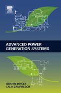
Note that for a mass change of 1 AMU the binding energy is ΔEb1 = 931.4 MeV. A factor that quantifies the nuclear stability of an isotope is given by the ratio of binding energy to the atomic mass, denoted with the nucleus stability factor (NSF)

Because the mass of proton and the mass of neutron as well are both of the order of ~ 1 AMU (see Table 6.3) it results that the mass of nucleus is approximately equal to the sum of protons and neutrons. Therefore, the NSF gives the binding energy per number of nuclides. When the binding energy per number of nuclides is higher the nucleus is more stable. In Figure 6.1 one can observe that 56Fe has about the maximum binding energy per nucleon (the peak is very close to 56Fe and corresponds to less abundant isotopes of 62Ni followed by 58Fe). The nucleus of 4He is also very stable, showing a peak with respect to its neighbors. This high stability is the reason this isotope results from many nuclear reactions, including fusion that is believed to occur in the sun’s core, where hydrogen is converted into 4He, or the alpha decay where a fast moving nucleus of 4He is generated.
Nuclei that have a small atomic mass (smaller than that of magnesium, atomic number Z = 24) tend to associate and form heavier nuclei through nuclear-fusion-type reactions. Atoms naturally repel each other, so fusion is easiest with these lightest atoms. However, to force the atoms together takes extreme pressure and temperature.
Elements with atomic mass in the range between magnesium and xenon (atomic number Z = 131) are relatively stable as the stability factor is relatively flat. For elements heavier than xenon the nucleus size becomes large, a fact that affects the balance of forces: attractive forces become weaker and the repulsive forces stronger. Therefore, heavy elements have the tendency to disintegrate into lighter elements through a nuclear fission reaction. The most easily fissionable elements are the isotopes are uranium-235 and plutonium-239.
Fissionable elements are flooded with neutrons causing the elements to split. When these radioactive isotopes split, they form new radioactive chemicals and release extra neutrons that create a chain reaction if other fissionable material is present. While uranium (atomic number 92), is the heaviest naturally occurring element, many other elements can be made by adding protons and neutrons to nuclei with the help of particle accelerators or nuclear reactors (Figure 6.1).
Besides fusion and fission reactions there is another nuclear process specific to unstable nuclei, namely the radioactive decay. The non-stable isotopes are denoted as radionuclides. In a radioactive decay a radionuclide discomposes by emitting nuclear radiation (alpha, beta, or gamma). Assume that a batch of matter contains N0 radionuclide at an initial moment. Due to decay reaction the number of radionuclides reduces after time t to N(t). The decay law expresses the time required for the number of radionuclides to reduce to half. The half-life time t1/2 is defined according to the following equation:

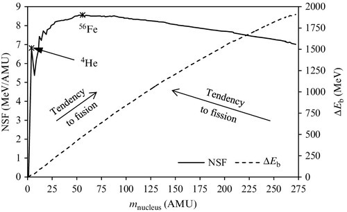
The half-life time of some radionuclides are given in Table 6.5. The half-life time is a very important parameter for designing nuclear fuel cycles. Nuclear fuels after use in a nuclear reactor are still radioactive in some measure. The half-life time allows for predicting the radiation decay of spent fuel in fuels repositories. The nuclear fuel cycle is detailed in the next section.
Table 6.5
Half-Life Time Values for Some Selected Radionuclides
| Radionuclide | Half-life time | Radionuclide | Half-life time |
| Tritium, 13H | 12.32 years | Carbon-14, 614C | 5730 years |
| Radon-222, 86222Rn | 3.8235 days | Thorium-232, 90232Th | 1.4 × 10¹⁰ years |
| Uranium-234, 92234U | 245,500 years | Uranium-235, 92235U | 7.038 × 10⁸ years |
| Uranium-238, 92238U | 4.468 × 10⁹ years | Plutonium-239, 94239Pu | 24,100 years |
Here we will focus on two main nuclear reactions that are relevant for power generation: thermonuclear fusion and fission. A basic reaction for thermonuclear fusion is
where the thermal energy emitted by the reaction is mainly gamma radiation. The most difficult problem with this reaction consists of making two deuterium nuclei collide.
There is considerable activation energy of ~ 0.02 MeV per collision required by reaction (6.2). However, the activation energy is negligible with respect to the amount of generated energy, which is 28.4 MeV for each collision. In order to transfer the activation energy for reaction initiation the temperature of the deuterons (deuterium nuclei) must be raised to 144 × 106 K, which is probably possible on the sun but definitely not on earth. Another thermonuclear reaction, practically demonstrated on earth through an explosive process, is the fusion of deuteron with triton (the tritium nucleus) according to
The activation energy for reaction (6.3) is ~ 10 keV, with an associated temperature of 77 × 106 K. In an explosive process (the hydrogen bomb) this temperature is achieved via a pilot reaction of uranium-235 fission. However, with current technology steady, controlled generation of thermal energy from the fusion reaction is not possible, especially because the process has an explosive nature with an extremely short duration of 1 μs. Research is underway to develop power generation technology from nuclear fission using various options such as electromagnetic fields and plasma and thermally induced shock waves to maintain the reaction confinement space at high temperature.
Nevertheless the most important reaction for nuclear power technology is currently the nuclear fission of uranium, a naturally occurring fuel resource. In a fission reaction a heavy nucleus is “bombarded” with a “slow” neutron. By capturing a neutron the nucleus enters into a metastable state. In order to reach equilibrium, the nucleus splits in two parts of about half weight and generates neutron radiation and energy.
The only known naturally occurring fissionable isotope is 92235U. However, the abundance of this isotope on earth is only 0.7%. Only two other fissionable artificial isotopes are known: the uranium isotope 92233U and the plutonium isotope 94239Pu. Both these isotopes can be produced starting from more abundant resources through neutron bombardment. Plutonium-239 is obtained from 92238U (~ 99.3% natural occurrence) through the following overall reaction
![]()
The artificial fissionable uranium isotope (uranium-233) is produced from thorium-232 (abundance ~ 100%) through the overall reaction
![]()
The nuclear fission process of uranium-235 requires one slow thermal neutron nth and generates a number κ > 1 of fast neutrons and heat (in the form of gamma radiation). The first step of the reaction is the bombardment of a nucleus of 92235U with one thermal neutron. As an intermediary product the process generates the metastable uranium-236, 92236mU. The fission reaction can be written in a simplified manner as follows:
The metastable 92236mU is formed, which further splits into two lighter nuclei, namely ![]() and
and ![]() , and emits κ neutrons. The mass number A1 (i.e., the number of nucleons) of the first element
, and emits κ neutrons. The mass number A1 (i.e., the number of nucleons) of the first element ![]() can be found in the range of 75–160, with a higher occurrence between 92 and 144. The resulting elements E1 and E2 have metastable nuclei and therefore will break apart, emitting gamma rays.
can be found in the range of 75–160, with a higher occurrence between 92 and 144. The resulting elements E1 and E2 have metastable nuclei and therefore will break apart, emitting gamma rays.
For reaction (6.4) the mean energy released by one mole of fissionable nuclear fuel (any of 92235U, 92233U, 94239Pu) is Qreleased = 200 MeV = 19.3 × 10¹² J. With this, one calculates 82.13 TJ per kg of 92235U, 82.83 TJ per kg of 92233U, and 80.75 TJ per kg of 94239Pu. For natural uranium fuel, accounting for the occurrence of 0.7%, the associated exergy is ~ 584 GJ/kg.
Example 6.1
Calculate the binding energy of tritium using the data from Tables 6.2–6.4.
• For tritium the following data is extracted from the tables:
• ![]()
• ![]()
• ![]()
• For protons and neutrons the following masses are found in the tables
• ![]()
• ![]()
• Using Equation (6.1) we obtain:
• first ![]()
• and thereafter ΔEb = c2 Δm = 931.4 × 0.0085571 = 7.9700827 MeV.
6.3 Nuclear Fuel
As mentioned in the introduction the fuel for nuclear power stations is extracted from uranium ore—uranite—which may contain up to 0.3% uranium oxide. Most uranite resources are found in Australia, including 23% of the global share. The map shown in Figure 6.2 illustrates the worldwide distribution of uranium fuel resources. The total known resources are on the order of 5 Tg (teragrams, 1012 g), with estimated theoretical resources (not yet proven) of 16 Tg. In addition to uranium there are about 20 Tt resources of fertile Thorium-232 fuel.

Once the fuel is extracted from natural deposits it follows a specific fuel processing chain until it is fed to the nuclear reactors. Practically all primary nuclear material used throughout the world is uranium, even though some limited applications may use thorium. The worldwide consumption of uranium fuel for power generation is represented on the map in Figure 6.3. For the future, thorium-232 is foreseen as the principal material to be extracted by mining for producing nuclear fuel.

After use at nuclear power stations the spent fuel—still radioactive—is further processed and eventually disposed. Various types of repositories for nuclear spent fuel exist, as will be presented later in this section, when the back-end of the fuel cycle will be discussed.
The nuclear fuel cycle comprises a front-end phase, a fuel utilization phase, and a back-end phase. The front-end covers all the processing, starting with mining and ending with fuel fabrication. The back-end includes fuel recycling, materials recovery, and disposal.
Figure 6.4 shows the main processing steps of a uranium fuel cycle and gives the approximate energy balances for producing 100 Mt of reactor fuel. At the mining site the uranium mineral is mined, milled, and extracted using chemical leaching. The resulting product is the uranium cake, which is the rough commercialized form of uranium fuel containing triuranium octaoxide (U3O8). About 260 Gt of ore is required to eventually produce 0.1 Gt of fuel. If enrichment is needed then U3O8 is converted to UF6 and processed through isotope separation to increase the amount of 235U to 3.5%. If enrichment is not needed the triuranium octaoxide is converted into uranium dioxide (UO2) which can be fed directly to reactors (e.g., CANDU). At the extraction phase of triuranium octaoxide about 520 Mt of product is generated for 100 Mt of fuel while close to 260 Gt of mill tailings are deposited.

The conversion of U3O8 to UO2 is through a thermal process (heating is required). If enrichment is required the uranium dioxide must be further converted to uranium hexafluoride. The steps for the entire conversion process from U3O8 to UO2 are illustrated in Figure 6.5. After uranium dioxide is obtained a hydro-fluorination process follows in which uranium dioxide is reacted with anhydrous hydrofluoric acid (HF). In a further conversion step the uranium tetrafluoride is combined with fluorine in gas phase to obtain uranium hexafluoride. The product extraction is done through distillation and crystallization using special steel drums. From 770 Mt of UF6 only 150 Mt of enriched fuel can be obtained; the residual material is stored for future use with the next generation of breeder reactor.

Further processing includes molding the uranium-fuel into a pellet form. There are various ways in which the fuel pellets can be assembled and clad. Recycled fertile materials are also embedded in fuel pellets (e.g., plutonium and depleted uranium). In commercial reactors for power generation the fuel is used in solid form. Liquid fuels also exist for advanced applications and research, including liquid uranyl salts and molten salts.
A typical fuel element is sintered and formed into cylindrical cartridges with a core of uranium which can be of a metallic material (the uranium), of an alloy (e.g., with aluminum), or of uranium dioxide (UO2) or uranium carbide (UC). One important aspect is fuel cladding. Nuclear fuel must be embedded in a layer of corrosion resistant material that allows for good heat transfer between the fuel core and the reactor coolant. Cladding has a reduced cross-section for the absorption of thermal neutrons and at the same time does not allow escape of radioactive materials. The cladding is made normally in zirconium alloys (2.5% niobium and 97.5% zirconium, which is highly penetrative to neutrons) or, as in more recent technologies, in silicon carbide. One of the problems with fuel cladding is its catalytic effect of splitting water molecules and hydrogen production; this effect is more pronounced in case of accidents when the temperature of the cladding increases and the catalytic activity enhances. Silicon carbide cladding shows very reduced water-splitting activity.
Recent advances in nuclear fuel manufacturing led to the development of tristructural isotropic-coated fuel particles (TRISO) which have improved safety and versatility. These fuel particles are designed to retain fission fragments under any possible circumstances, as they have a strong negative coefficient of reactivity. This means that TRISO fuel is intrinsically safe because there is no need for active cooling in case of accident and the reaction stops immediately when the neutron rate is reduced.
TRISO comprises a 0.5 mm spherical fuel particle of uranium dioxide which is coated in four protective shells, as shown in Figure 6.6. The outer layer acts a pressure vessel, not allowing the passage of any radioactive particles up to temperatures as high as 1900 K. TRISO particles have a diameter of 1 mm and can be formed as pebbles (of ~ 6 cm in diameter) or as hollow cylinders of 25 mm in diameter and 4 mm in length.

After fuel is used, it is discharged from the reactor and stored in interim locations. Further, the used uranium is transported to disposal places for permanent storage, or reused, depending on the case. For breeding reactors, the uranium fuel is always recycled. In this case, the fuel is reprocessed to extract the fertile and the fissionable isotopes which then are transported to production places to obtain new fuel pellets. The materials remaining after reprocessing can be processed even more by recovering valuable isotopes for other uses.
The nuclear waste comprises many radioactive isotopes and transuranic elements which have an extremely long half-life time. Some of these elements are neptunium, plutonium, tectenium, and iodine. Keeping such elements for a long time implies vitrification or calcination, which embeds them in an amorphous matter with which they do not react for a long period of time.
An interesting aspect is that the radiation emitted by nuclear waste generates heat which is on the order of about 1.5 kW per ton of uranium in 10 years. This heat can in principle be used as a heat source either to generate power with low-temperature differential heat engines or for heating applications. However, there is a lack of confidence regarding the safety of using waste cooling systems as heat sources and such solutions have not been implemented to date.
After appropriate packing, the waste is deposited in long-term geological storage locations excavated in the form of tunnels in pits at more than 1000 m below the earth surface (see IAEA, 2011). Nuclear wastes can be categorized in three classes, namely:
• Low-level waste—which comprises the residual radioactive material from medical and industrial facilities which use radionuclides for various processes involving, for example, gamma- or X-ray generation. Some of the radioactive material disposed by other nuclear facilities is also low-level waste.
• High-level waste—generated during the nuclear fuel cycle, consisting of solid and liquid material which is highly radioactive.
• Transuranic waste—comprising radioactive materials with a decay time of longer than 20 years which emit alpha particles with sensible intensity.
Among all categories the safe disposal of high-level waste is the most important. These wastes are stored in underground repositories built in several places throughout the world, one of them being at Yucca Mountain in the United States, planned to accommodate 70 kt of nuclear waste. The countries that have national plans for nuclear waste repositories are the following:
• United States—storing the waste in tuff host rock in Yucca Mountain
• Finland—to be completed in 2020, storing the waste in granite host rock, at Olkiluoto location
• Germany—to be completed in 2020, with storage in salt, at Gorleben location
• France—to be completed by 2020, with storage in clay and granite
• Canada—to be completed in 2025, with storage in granite
• Japan—to be completed by 2030, with storage in sedimentary rock and granite
• Switzerland—with opening target in 2050, and storage in granite and clay
• Sweden—with completion target in 2020, and storage in granite host rock
There are various safety measures that must be taken to avoid direct exposure of humans and environment to radiation emitted by nuclear waste. Shielding is applied wherever possible. Also the spent fuel assemblies are placed in cooling pools and transferred into shielded protective canisters. The hazard that is possibly created by the nuclear waste is the dose that can be received through inhalation of escaped radionuclides. The maximum dose rate that a person can take is of 20–50 mSv per annum, where “mSv” stands for millisievert, which is the equivalent dose to a tissue, a calculation based on the absorbed radiation dose and factors dependent on the radiation type and other relevant parameters, such that the quantity represents a quantitative measure of radiation effects; note that 1 Sv = 1 m2s− 2.
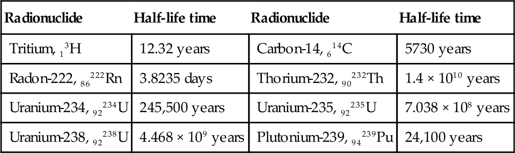
A brief comparison of nuclear fuel, fossil fuels, and biomass is given in Table 6.6. Definitively, the nuclear technology produces the most power per unit of hardware volume or mass. Coal and biomass combustion facilities are massive because they must include fuel handling facilities and large stacks; this decreases the energy density of the generated power. However, the Carnot factor, and therefore the exergy efficiency, associated with combustion technologies is the highest.
Table 6.6
Comparison of Nuclear Fuel with Fossil Fuels and Biomass
| Fuel | Heat transfer medium | Temperature (°C) | Carnot factor | Energy density (approximate values) | GHG emissions | |
| MJ/t | MJ/m3 | |||||
| Nuclear fuel (fission) | Liquid | 300–500 | 0.5–0.6 | 83,000 | 1,550,000 | Indirect: associated with reactor construction |
| Gas | 700–950 | 0.7–0.75 | 16,000 | 300,000 | ||
| Fossil fuel | Flue gas | 1000–1500 | 0.76–0.83 | 0.045 | 0.035 | CO2 in flue gas; About 0.5–1 t CO2 emitted per kWh thermal |
| Biomass | Flue gas | 500–1500 | 0.62–0.83 | 0.017 | 0.015 | Neutral |
6.4 Nuclear Reactors
6.4.1 Reactivity Control
The steady and safe operation of a nuclear reactor requires the maintaining of a balance between the energy generated by the fission reaction and the energy removed by heat transfer from the fuel cladding to the coolant. Both the heat generation rate and the heat transfer rate can be adjusted using specific mechanisms. The heat generation rate depends on the reaction rate.
The nuclear reaction rate is related to the rate of neutrons that are able to initiate new reactions. Moreover, the stable operation of the reactor depends on the balance of neutrons generated by the reaction versus the neutrons absorbed by the surrounding medium. Once it is produced, the fission reaction of produces κ fast neutrons that, in principle, can be slowed down and further used to initiate new fission reactions. This observation suggests that it is possible to obtain a self-sustained nuclear fission reaction (chain reaction). Two parameters influence the balance between the generated and absorbed neutrons: the neutron cross-section and the critical mass; these parameters are very important in the design of fission nuclear reactors.
The neutron cross-section expresses the likelihood of interaction between a neutron and a target nucleus. This probabilistic quantity is measured in units of area (e.g., cm2). The typical values are on the order of 10− 24 cm2, therefore a special submultiple of the unit for area is used, namely the barn, where 1 barn = 10− 24 cm2. The cross-section denoted with σ is defined implicitly from the following equation

where ![]() is the rate of interaction [nuclear interactions per second per target atom] and ϕ is the neutron flux [neutrons per second and cross-section perpendicular to the neutron beam] and σ is measured in barn of cross-section times the number of interactions per neutrons per target atom.
is the rate of interaction [nuclear interactions per second per target atom] and ϕ is the neutron flux [neutrons per second and cross-section perpendicular to the neutron beam] and σ is measured in barn of cross-section times the number of interactions per neutrons per target atom.
The cross-section values for fission fuel encounter by neutrons vary in the range of 0.05–300 barn. The cross-section of heavy water encounter by neutrons is 3–4 barn when the neutrons are scattered. In a nuclear reactor a certain amount of uranium fuel is placed in a special vessel surrounded by a coolant and a moderator, which have the role of heat transfer and neutron deceleration respectively. Neurons are emitted by the radioisotope material due to its decay. When atoms of uranium are hit by the neutrons some of them produce fission and generate many other neutrons. Some of these hit other fuel atoms and generate new fission reactions. If more atoms of fuel (or more mass) are brought together then there is a higher probability of initiating a chain reaction.
The critical mass represents the smallest amount of fissile fuel which must be placed in a reaction confinement to maintain a chained nuclear reaction. If the mass of fissile material is higher than critical mass then higher chances exist that the reaction rate will increase, whereas when the mass is less than critical the reaction will cease as insufficient neutrons are emitted to maintain the chain reaction.
The following three cases of fission reaction are possible, depending on the parameter κ—denoted as the neutron multiplication factor—which represents the number of neutrons producing a new fission per neutron that initiates the reaction:

When κ = 1 the reaction proceeds at steady rate and the reactor operates at “criticality.” When κ > 1 the reactor is in supercritical ranges, therefore the reaction and heat release rates amplify. The rate can grow extremely fast and explosion becomes possible. When the reactor operates in subcritical range the process slows down. Note that the critical mass for uranium-235 is ~ 50 kg (the corresponding volume is ~ 3 l).
The nuclear reaction rate can be controlled (and maintained stable) in two ways, corresponding to two different reactor technologies: (i) by slowing the neutrons as in “thermal reactor” technology and (ii) by enriching the fissile material in a proper proportion as in “fast neutron reactor” technology. The cross-section parameter plays the most important role in design for both options.
The fast neutron reactors use nuclear fuel blended with enriched fissile material. The enrichment is done such the probability of fast neutrons colliding with fissile atoms becomes high enough to maintain the chain reaction. Henceforth these reactors do not need any moderator because the there is no need to slow down the neutrons. When bombarded with neutrons, the fertile materials transform into fissionable fuel. Uranium-238 can be made fissile in about two and one-half days, thus natural-uranium-based reactors are called “Fast Breeding Reactors” (FBR). In an FBR, ~ 2.7 neutrons are generated for one absorbed neutron to produce fission, while 1.7 neutrons produce fuel breeding. Thorium breeds slower than natural uranium, often after about 21 days. Thus, thorium-based reactors are called “Thermal Breeding Reactors” (TBR).
Thermal reactors use a neutron moderator, which contains a material that slows down the fast neutrons that result from each individual fission reaction. The kinetic energy of the slow neutron—which is named the thermal neutron—is on the order of magnitude of the surroundings medium. Being slow, the thermal neutrons have a higher cross-section than the fast neutrons; in other words, the probability of colliding with fissionable material is higher.
Regardless of the specific type of nuclear reactor the thermal energy transfer process is similar: heat is transferred from a hot core by thermal conduction to the cladding surface; further heat is transferred by convection to a heat transfer fluid. Figure 6.7 illustrates a typical fuel-coolant arrangement for pressurized water-cooled reactors. The core temperature is about 2200 °C, whereas the temperature of the Zircaloy cladding is ~ 340 °C. The average temperature of water coolant is 305 °C, with water at the entrance being at Tc,in = 290°C and at the exit Tc,out = 315 °C.

Of major importance in fission reactor design is the evaluation of heat generation rate per unit of volume, q‴. This parameter varies across the reactor core volume and is influenced primarily by the intensity of the neutron and gamma radiation produced by the nuclear reaction. In turn the radiation intensity is influenced by the kinetic energy of the emitted particles, the flux density energy spectrum, the density of various atomic constituents, and the atomic cross-sections.
In the design process of the reactor the heat conduction equation must be solved in a region around the fissionable fuel where heat is generated. The medium is non-homogenous, therefore the general heat conduction equation in differential form is

where ![]() is the volumetric heat generation rate which varies in time and space (axial symmetry is assumed), r is the radial coordinate, and k is the thermal conductivity.
is the volumetric heat generation rate which varies in time and space (axial symmetry is assumed), r is the radial coordinate, and k is the thermal conductivity.
The heat conduction problem can be approximated as one-dimensional axisymmetric. The volumetric heat generation rate can be determined with the help of the parameter ε defined as the average energy dissipated by a single interaction and with the help of parameter N‴, representing the number of fissile nuclei per unit of volume. Note that the average energy dissipated, the cross-section, the particle flux, and the numbers of atoms per unit of volume vary spatially and temporarily. Moreover, the nature of the radiation varies and secondary effects can occur (e.g., scattering, low energy X-ray emission, ionization, photon emission, beta emission, Compton scattering, etc.). The rate of nuclear interactions given by Equation (6.5) must be multiplied with the number of fissile nuclei per unit of volume and with the energy dissipation parameter so that the rate of heat generation is obtained; hence one has
In Equation (6.6) one must account for thermal conductivity variation with the temperature. The average thermal conductivity of UO2 can be taken to be about 6 W/mK. However, one must note that for certain operating conditions when the UO2 fuel temperature reaches 2800 °C the fuel melts and its thermal conductivity varies sharply. The melting temperature of Zircaloy is around 1900 °C, whereas its average thermal conductivity is 10 W/mK.
For a common case in practice, fuel rods have a diameter of 5 mm and generate a linear heat flux of 15 kW/m; therefore at the rod surface the heat flux density q‴ is superior to 750 MW/m3. The temperature difference between the core and the rod surface is about 2000 °C. The temperature also varies along the fuel rod.
For preliminary design calculation purposes it is customary to assume that the fuel assemblies are cylindrical of radius Rf and the height z; they are also assumed to be uniformly distributed in the cross-section of the reactor. Then the heat generated by a fuel assembly located at the radius r in the reactor cross-section (the radial distance from the center of the reactor to the center of the rod) is given by

If one denotes with ![]() the heat rate delivered to the heat transfer fluid (coolant), nfuel the number of fuel assemblies, efuel = 200 MeV the average energy generated by the fission reaction of a single fuel atom, and ediss < efuel the actual energy dissipated by the fuel rods for a single interaction, then the maximum heat that could be generated by the reactor if all fuel elements would generate at the same rate qmax can be approximated with the simplified equation given by Lamarsh and Baratta (2001):
the heat rate delivered to the heat transfer fluid (coolant), nfuel the number of fuel assemblies, efuel = 200 MeV the average energy generated by the fission reaction of a single fuel atom, and ediss < efuel the actual energy dissipated by the fuel rods for a single interaction, then the maximum heat that could be generated by the reactor if all fuel elements would generate at the same rate qmax can be approximated with the simplified equation given by Lamarsh and Baratta (2001):

Therefore, the maximum volumetric heat generation for a fuel rod of radius Rf and length z is obtained by dividing ![]() by the rod volume as follows:
by the rod volume as follows:

The volumetric heat generation at any radius r in a reactor cross-section is obtained by integration of Equation (6.8); according to Lamarsh and Baratta (2001) this integration leads to

where Rr is the reactor radius and J0 is the zero order Bessel function of first kind.
Example 6.2
A cylindrical nuclear reactor of the radius Rr = 2 m is loaded with nfuel = 50, 000 fuel elements of cylindrical shape. It is given that the energy dissipated by nuclear interaction is ediss = 185 MeV and the output heat by the reactor is 1 GW. Calculate the maximum heat rate and the heat rate at middle radius and at 5% from the reactor periphery.
• First one calculates the maximum heat rate according to Equation (6.9)

• With Equation (6.11) and ![]() kW the heat rate at any radius r from the reactor center is given by
kW the heat rate at any radius r from the reactor center is given by
![]()
• Therefore, at half the reactor radius Rr = 1 m one gets
![]()
• Further one calculates the radius corresponding to a location at 5% from reactor periphery to be r = 0.95, Rr = 1.9 m; hence one has
![]()
6.4.2 Exergy Destructions in a Nuclear Reactor
Nuclear radiation has very high exergy content, practically 100%. Based on the kinetic theory of ideal gases, the energy associated with a particle is e = 3/2kBT where kB = 1.38 × 10− 23J/K is the Boltzmann constant. The neutrons emitted by the fission reaction are fast neutrons which are immediately thermalized by the moderator. The energy spectrum of fast neutrons is 1–20 MeV. Therefore, the particle temperature associated with this kinetic energy is extremely high; for 1 MeV it corresponds to 7.7E9 K, while for 20 MeV one has 1.5E11 K. Therefore, the Carnot factor of the neutron radiation can be assumed to be unity when the reference temperature is on the order of 300 K. This means that the nuclear energy is assimilated to an exergy.
Nevertheless, the exergy of the neutron radiation is destroyed in the reactor by multiple processes. Figure 6.8 represents a simplified reactor model which is useful for identifying the main exergy destruction processes within a general nuclear reactor. In Figure 6.8, the system components are assimilated with boxes. In each box the specific process that take place is indicated. The arrows that connect the boxes represent transfer processes such as neutron radiation, conduction heat transfer, combined heat transfer, and fluid flow, according to the legend. The nuclear fission reaction occurs in the fuel pellet core and emits neutron radiation (mainly) and gamma radiation or other minor particles. The main amount of nuclear radiation interacts with fuel pellets (#1) and generates heating. Some neutron radiation escapes to the moderator (#2) where it is scattered back or partially converts to heating. Other neutron radiation (#3) reaches auxiliary components of the reactor (e.g., the shielding structure) and is converted to heat. The hot fuel pellets transfer heat though the heat conduction mechanism towards the pellet surface (#4) and further to the cladding surface (#5).

The cladding surface interacts through combined heat transfer mechanisms (mainly conduction and convection) with the heat transfer fluid (#6) which is heated from its entrance temperature (at #7) to its exit temperature (at #8). The heat generated within the auxiliary components of the reactor is transferred by convection (or convection conduction) heat transfer to the surroundings moderator (#9). The moderator is typically circulated to a cooling system to extract the moderator heat. It enters in the reactor colder at (#10) and exists warmed at (#11). Simple energy and exergy balance equations for the reactor allow for defining energy and exergy efficiencies. Table 6.7 gives these equations and definitions.
Table 6.7
Balance Equation and Efficiency Definition Equations for Generic Nuclear Reactor


Example 6.3
Consider a pressurized light water reactor modeled according to the model in Figure 6.8 where stream 10–11 is replaced with a heat leak flux from the reactor vessel to the environment. Calculate the energy and exergy efficiency of the reactor as well as overall exergy destruction and exergy destruction for each of the processes. It is given that: the nuclear radiation transfer to the pellet core is 1 GW (for all reactor), temperature of the pellet core is 1900 K, temperature at the pellet surface is 675 K, temperature at cladding surface is 600 K, temperature of the heat transfer fluid at inlet is 500 K and at outlet 550 K, nuclear radiation dissipated into the moderator is 8 MW, and radiation dissipated into auxiliary components is 2 MW.
• First one calculates the energy (and exergy) input from the radiation
![]()
• The energy transferred to the heat transfer fluid is ![]() . Therefore the energy efficiency is η = 1000/1010 = 99%.
. Therefore the energy efficiency is η = 1000/1010 = 99%.
• The mass flow rate of heat transfer fluid results from its energy balance
![]()
• The exergy lost by the moderator is determined based on the assumed average temperature of the moderator; as this is a pressurized light water moderator the average moderator temperature is the same as the average temperature of the heat transfer fluid, thus ![]() . The reference temperature is assumed to be the temperature of a lake used for condenser cooling and is taken as T0 = 15 °C. Therefore the exergy lost by the reactor is
. The reference temperature is assumed to be the temperature of a lake used for condenser cooling and is taken as T0 = 15 °C. Therefore the exergy lost by the reactor is

• The exergy transferred to the heat transfer fluid is ![]() ; noting that the enthalpy rate difference for heat transfer fluid is
; noting that the enthalpy rate difference for heat transfer fluid is ![]() , the
, the ![]() becomes
becomes
![]()
where the entropy rate difference can be calculated from:

• Therefore, ![]() and the exergy efficiency becomes
and the exergy efficiency becomes

• The exergy destructions then become
• Overall: ![]()
• Fuel pellet heating: ![]()
• Conduction through pellets: ![]()
• Conduction through cladding: ![]()
• Convection to heat transfer fluid: ![]()
• Auxiliaries heating: ![]()
• Moderator heating and heat loss: ![]()
6.4.3 Conventional Reactors
Reactor technology has evolved toward a set of established concepts, most of which are employed today in nuclear power stations. In this section we will discuss the past and established concepts of nuclear reactors, with a focus on pressurized water and boiling water concepts, which are the most used today. A classification of established concepts of nuclear reactors is shown in Figure 6.9. The first generation of nuclear reactors comprises four major concepts; from this first generation none of the power plants are in use today. The concepts developed in the first generation are: a boiling water reactor (BWR), gas-cooled reactor, liquid metal fast breeder reactor (LMFBR), and pressurized heavy water reactor (PHWR). Some typical examples of first generation reactors are listed as follows:

• BWR—DGS 1 (Dresden Generating Station 1, Illinois), with 210 MW installed power generation, commissioned 1960, decommissioned 1990.
• LMFBR—Fermi 1 from Monroe USA with 100 MW installed power generation; commissioned 1956, decommissioned 1972.
• Gas-cooled reactor—Mangox 1 (Clader Hall, UK) with 60 MW installed power generation, commissioned 1956, decommissioned 2003.
• PHWR—NPD Rolphton (Ontario), with 19.5 MW installed power generation, commissioned 1961, decommissioned 1987.
Other examples are the Shippingport Atomic Power Station commissioned in 1958 and decommissioned in 1982, with 60 MW installed power generation and a thermal breeder light water moderator, and the Obninsk Nuclear Power Station, built in the former Soviet Union (FSU), with 5 MWe installed power generation, commissioned in 1954 and decommissioned in 2002.
One of the most used types of reactors is the pressurized water reactor. The earliest design option for a pressurized water reactor is the PHWR, which uses heavy water as moderator. The operating principle of the PHWR is shown in Figure 6.10 as it was developed by AECL (Atomic Energy Canada Ltd) under the name CANDU (CANada Deuterium Uranium). The fuel is placed in tubes through which PHWR coolant flows. The coolant transfers the nuclear heat to a heat exchanger, which is typically a steam generator; the produced heat comes to about 350 °C. Outside the pressure tubes there is the moderator, consisting of a heavy water bath in which the tubes are submerged.

The pressure in the moderator is around 1 bar. The moderator is continuously cooled and the heat is rejected at about 80 °C. The fuel rods can be replaced or extracted independently at any time though special mechanisms. In the moderator bath there are a series of graphite rods (not shown) with the role of attenuating the neutron flux and thus controlling the reaction rate and criticality. The CANDU reactor evolved with improved options and increased capacity based on the same pressure tube concept and the use of natural uranium and heavy water. The model CANDU-6 corresponds to the second generation of nuclear reactors and has a 500–600-MWe capacity. The Enhanced CANDU reactor EC6 has an output of 740 MWe and has the ability to operate at part-load conditions.
The core concept of the BWR appertains to the first generation of nuclear reactors (see Figure 6.9). The BWR uses water as a moderator and coolant at the same time, with the difference that the reactor produces saturated steam. Figure 6.11 shows a simplified schematic of a BWR. Typically the pressure in the BWR is of 75 bar and the corresponding temperature is 285 °C. The reactor has a special construction which allows for a stable boiling process. When it enters in the reactor, water is first guided into a downcomer where it is preheated. It then rises and flows around the vertical fuel rods though the reactor core region. The resulting twophase flow, having ~ 15% vapor quality, is directed toward a cyclone separator and steam dryer at the top of the reactor, where the saturated steam is collected. In general layout, the reactor is kept in a containment structure, while the steam turbine, the condenser, and the pumps are placed on the exterior.

Gas-cooled reactors (GCR) were first developed in the United Kingdom (MAGOX reactor, see above). In the original MAGOX the coolant was carbon dioxide pressurized at ~ 20 bar. The fuel is natural uranium and the reactor is of fast breeding type. The moderator is graphite. The temperature level of the generated heat is compatible with linkage to a steam power plant. Figure 6.12 shows the simplified diagram of a gas cooled reactor which uses carbon dioxide coolant.

The most used in the United States is the pressurized water reactor (PWR), which has found applications in power generation and propulsion of marine vessels like submarines, aircraft carriers, and ice breakers. The simplified diagram of the PWR is illustrated in Figure 6.13 and comprises the fuel bundles, the moderator vessel, the pressurizer vessel, the heat exchanger (steam generator), and the coolant pump. The PWR uses slightly enriched uranium in the form of UO2 containing about 3% 92235U placed in tubes of Zircaloy and sunk in light water, which plays the role of moderator. The fuel and the moderator are kept in a pressure vessel designed to operate at about 155 bar pressure; water boils at 344 °C.

However, in the reactor (pressure) vessel water is heated from 275–315 °C and always remains in liquid state. In fact, in order to enhance the heat transfer between the fuel rods and the water, the flow is set such that subcooled nucleate boiling occurs at the surface of the rods; the small vapor bubbles formed are immediately absorbed into the subcooled liquid water. Overall, the operation is very stable.
The light water is an excellent moderator. In order to control the reaction rate, additional moderators are used in the form of movable bars made from boron carbide or Ag–In–Cd. The pressure is maintained through a pressure vessel equipped with submerged electric heaters meant to maintain a vapor pressure of 155 bar; the vapor is located at the top of the pressurizer, while its bottom is always full of subcooled liquid. A heat exchanger is used to deliver the nuclear heat from the primary circuit to a secondary circuit, which may be a steam generator aimed to run a turbine which commonly turns a generator or propels a marine vehicle. The generated steam is typically 275 °C and 60 bar.
The VVER 440, which refers to a second generation nuclear reactor, was first commissioned before 1970, with the most common design version known as V230, with a 440-MWe output. It is cooled and moderated with light water; therefore the Russian VVER is a version of the PWR. There are some design features in the VVER that distinguish it from the PWR, namely its use of a horizontal boiler instead of a vertical arrangement.
The Generation III nuclear reactors are based on former design principles but with improved efficiency, modularity, safety, standardization of components, 1.5 times increased lifetime (~ 60 years), and reduced capital and maintenance costs. The reactors of Generation III were commissioned between about 1990 and 2005. They include the Enhanced CANDU-6 (EC6) reactor, the VVER-1000/392 pressurized water reactor, the BARC–AHWR (Indian advanced heavy water reactor), the advanced pressurized water reactor (APWR), and the advanced boiling water reactor (ABWR). Note that the ABWR was developed by a GE–HNE consortium, which included General Electric (GE) and Hitachi Nuclear Energy (HNE). The APWR was developed by Mitsubishi Heavy Industries (MHI). The VVER-1000 has about 33% efficiency with a net power generation of 1000 MWe and a hottest coolant temperature of 321 °C. The APWR capacity is ~ 1500 MWe and units are in operation in Japan.
Example 6.4
Consider a pressurized water reactor (of thermal type) having a fuel rod radius of Rf = 5 mm, clad with a Zircaloy shell of t = 0.5 mm thickness, and with a rod height of z = 4 m. One can calculate the heat flux and the temperature of the cladding outer surface provided that the temperature in the core is given; assume that the core temperature is Tc = 2200 °C. Calculate the volumetric heat flux rate, the heat flux rate, and the temperature at the cladding surface. The thermal conductivity of the fuel is given as kf = 2 W/mK and that of the cladding as kc = 20 W/mK.
• First one can calculate the volumetric heat generation at the axis; one obtains

• The energy balance over the fuel rod is written as
![]()
where the LHS represents the heat generated in the rod and the RHS represent the heat flux exiting the lateral rod surface; ![]() is the heat flux at the outer cladding.
is the heat flux at the outer cladding.
• One obtains ![]() .
.
• If one denotes Tf,s the temperature at the fuel rod surface, and ΔTf = Tc − Tf,s is the difference of temperature between the rod core and the rod surface, then, from the equation for heat transfer by conduction for the cylinders, one can easily obtain
![]()
• It results in ΔTf = 1500 °C. On the other hand, the heat transfer equation though the cladding shell is

• From this equation, one obtains ΔTc = 300 ° C.
• From these results it follows that:
• Tf,s = 2200 − 1500 = 700 °C
• The temperature at the cladding surface is Tc,s = 400 °C.
• Therefore, the temperature at which the heat transfer fluid is delivered by the nuclear reactor is estimated at Tout = 350 °C.
• As the reactor is of thermal type, 5–10% of the nuclear heat is transmitted to the moderator and is considered to be lost. Therefore, the energy efficiency is η = 90–95 %. The Carnot factor in this example is calculated as
![]()
• The exergy efficiency of the reactor becomes
![]()
6.4.4 Advanced Nuclear Reactors
There are a number of advanced nuclear reactors currently in the design stage. This means that the conceptual phase of development is ended and the detailed design is underway. These reactors are sometimes denoted as Generation III + and are the following:
• Advanced CANDU (ACR-1000) reactor.
• European pressurized reactor (EPR).
• VVER-1200.
• APWR-IV.
• ESBWR—economic simplified BWR.
• AP-1000 reactor.
• APR-1400.
• EU–APWR.
• IFR—integral fast reactor.
• PBR—pebble bed reactor.
• HTGCR—high-temperature gas-cooled reactor.
• SSTAR—small sealed transportable autonomous reactor.
• CAESAR—clean, environmentally safe advanced reactor.
• SR—subcritical reactor.
• TBR—thorium-based reactor.
• AHWR—advanced heavy water reactor.
• KAMINI—Uranium-233 based reactor.
The ACR-1000 is a hybrid design that uses heavy water as a moderator and light water as a coolant to generate 1200 MWe. It includes enhanced safety features with respect to former CANDU versions and it is to be commissioned by 2016. The AP-1000 is the Westinghouse Generation III + design with ~ 1150 MWe output. The EPR was designed by an international consortium of Siemens AG, Areva NP, and Electricité de France (EDF). It is a PWR-type reactor with 37% efficiency, generating 1650 MWe. In Finland, construction of the first EPR power plant started in 2005 with a plan to be commissioned in 2013. The ESBWR is a BWR designed by GE–HNE with a capacity of 1520 MWe and lifetime of 60 years. APR-1400 is an APWR adopted by South Korea, with 1455 MWe and first commissioning expected in 2013. The VVER-1200 of Generation III + is an evolution of the VVER-1000 with a lifetime expectancy of 50 years and power range of 1200–1300 MWe. The EU–APWR is a version of APWR by MHI to be commissioned in Europe at a power generation capacity of ~ 1600 MWe.
In South Africa, the pebble bed modular reactor (PBMR) was under development for almost 16 years under the funding of Eskom, its partners, and the South African government (Koster et al., 2003). No equipment failure or human error can produce an accident with the PBMR because its design and construction are inherently safe. This greatly simplifies the safety design of the system. Its design evolved from the high-temperature reactor of Siemens to a scheme that uses a Brayton cycle turbine with a closed loop. The hot outlet temperature is 900 °C, with around 400 MW of thermal output per unit. Currently, the PBMR technology is pending as it has not found the necessary investors.
India is the sole country that has developed a research program to study the thorium fuel cycle for nuclear power reactors. The government typically has policy programs formulated as 5-year plans. Five “nuclear energy parks” were set up by the Indian government. The Bhabha Atomic Research Centre (BARC) of India leads the research activities on the country’s nuclear reactors. Two of the Indian nuclear power stations are coupled with desalination plants (WNA, 2013). In the vicinity of Madras, a prototype of a fast breeder reactor (FBR) of 500 MWe is under construction by an Indian consortium that includes the government and Bharatiya Nabhikiya Vidyut Nigam Ltd.
The FBR reactor is a thorium-based reactor project in India. It will be fueled with uranium–plutonium fuel and it will have a blanket of uranium/thorium to breed fissile 233U. The thorium-based breeder may become one of the most remarkable non-GIF next generation commercial reactors, as it is able to use the large amount of thorium resources in India. Six more FBRs are planned by 2020. In a third phase, the fissile 233U and plutonium from FBR will be transferred to existing Indian advanced heavy water reactors where they will generate about one-third of the power, the rest being supplied by additional thorium fuel.
The Russian Federation is very advanced in fast breeder reactor research. Russian federal funding for novel nuclear reactors is around 2 billion USD for a multi-year period (until ~ 2020, see Table 6.8). The modular SVBR 100 concept is a low power lead–bismuth-cooled fast breeder reactor for pressurized process steam or power generation. This small reactor is very versatile and can be configured for many applications. Russia led the IAEA INPRO project in 2001.
Table 6.8
Russian Next Generation of Commercial Nuclear Reactors

Source: WNA (2013).
6.4.5 Generation IV Nuclear Reactors
The US DOE promoted an international initiative on the development of advanced nuclear reactors for power and process heat which was established in 2001 as the Generation IV International Forum (GIF). The concept “Generation IV” has been proposed by the DOE as a method of facilitating international cooperation in the development of advanced nuclear systems by the 2030s and beyond. Generation IV reactors are categorized as theoretical designs currently under research.
The US DOE implemented a Generation IV national program starting in 2002. The terminology “nuclear energy systems” is used instead of nuclear reactors to indicate that the fourth generation is also aimed also at power and process heat production. In January 2000, the Office of Nuclear Energy, Science, and Technology of the DOE facilitated discussions of senior representatives from nine countries (Argentina, Brazil, Canada, France, Japan, Republic of Korea, South Africa, the United Kingdom and the United States) aiming to establish an international collaboration in the development of Generation IV nuclear energy systems. Three other countries later adhered to the charter, including Switzerland (2002), China, and the Russian Federation (2006). The European Union adhered to GIF in 2003 with its atomic energy agency, Euratom. The International Atomic Energy Agency (IAEA) and the Nuclear Energy Agency of the Organisation for Economic Co-operation and Development (OECD) participate in the charter as permanent observers.
The fourth generation of nuclear reactors is represented by six reactor concepts selected by the GIF. These concepts will be discussed in more detail in Chapter 7. Here they are briefly introduced with the purpose of facilitating the discussion of the technology roadmap, research issues, and existing research programs. GIF aims at the development of safer, sustainable, more economical, physically secure, and proliferation-resistant nuclear reactors. Generation IV reactors are intended to become commercially available by 2030. According to GIF (2013), the Generation IV nuclear reactors include the following designs.
• Gas-cooled fast reactor (GFR)—it features a fast-neutron-spectrum, helium-cooled reactor and closed fuel cycle (spent fuel is reprocessed and reused); it generates 1200 MWe and processes heat at 850 °C.
• Very-high-temperature reactor (VHTR)—it is a graphite-moderated, helium-cooled reactor with a once-through uranium fuel cycle (spent fuel is not reprocessed); it has a projected core outlet temperature of 1000 °C and the units have a 600 MW output.
• Supercritical-water-cooled reactor (SCWR)—this is a high-temperature, high-pressure water-cooled reactor that operates above the thermodynamic critical point of water; it is planned for a 1700-MWe output and a core outlet temperature in the range of ~ 500–650 °C.
• Sodium-cooled fast reactor (SFR)—it features a fast-spectrum, sodium-cooled reactor and closed fuel cycle for efficient management of actinides and conversion of fertile uranium; its core outlet temperature is 550 °C, and it is planned for three capacities: low (50–150 MWe), intermediate (300–600 MWe) and large (600–1500 MWe).
• Lead-cooled fast reactor (LFR)—it features a fast-spectrum lead/bismuth eutectic liquid-metal-cooled reactor and a closed fuel cycle for efficient conversion of fertile uranium and management of actinides. It includes two versions: (i) small size at 19.8 MWe and 567 °C core outlet temperature and (ii) high power at 600 MWe and 480 °C.
• Molten salt reactor (MSR)—it produces fission power in a circulating molten salt fuel mixture with an epithermal-spectrum reactor and a full actinide recycling fuel cycle. The reference capacity is 1000 MWe with a coolant exit from the core at 700–800 °C.
The SCWR represents an evolution of older reactor concepts such as the BWR, PWR, and PHWR, which use water as a coolant. In an SWCR, the pressure of the water coolant in the reactor is maintained over a critical value of 22.1 MPa such that water does not boil. This simplifies the design, increases the efficiency up to 50%, and addresses the issues related to safety, although more stress occurs on materials. There are two design options of SWCR, either with pressure tubes or a pressure vessel. Variants of SWCR concepts with pressure tubes are under development in Canada (SCWR–CANDU) and Russia, while variants with pressure vessels are under development in France, Japan, and Korea.
The planned electricity generation range with SWCR reaches up to 1.5 GW electric (no SCWR has been built yet to date). The system uses light water coolant at an operational pressure of 25 MPa. It has design flexibility, with an inlet temperature up to ~ 625 K and outlet up to 900 K, with both thermal (up to 60 GW days per ton of heavy metal) and fast (up to 120 GW days per ton of heavy metal) neutron spectra, three types of fuel (uranium dioxide, thorium, and mixed oxide fuel), two types of fuel cycles (once-through or closed) and three variants of moderators (light water, heavy water, or zirconium hydride solid moderator).
Figure 6.14 illustrates the two main design concepts of the SWCR, namely the pressure vessel configuration and the pressure tube configuration. The CANDU–SWCR configuration uses pressure tubes as illustrated in Figure 6.14a. The CANDU–SWCR, described also in Naterer et al. (2013), has a similar geometrical arrangement to traditional heavy water reactors developed by AECL (Atomic Energy of Canada Limited). However, in the supercritical version, light water is circulated in tubes and the nuclear fuel is based on a thorium fuel cycle. The moderator is heavy water which surrounds the pressure tubes in a calandria vessel with enhanced safety functions.
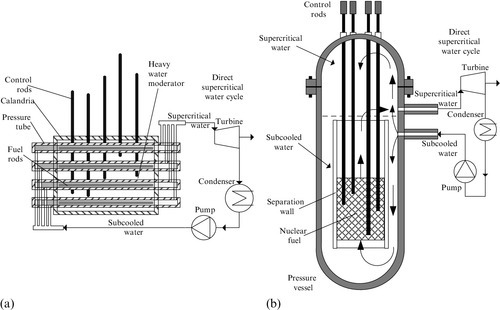
The pressure vessel configuration—illustrated in Figure 6.14b—represents an evolution of the BWR and PWR concepts where the nuclear fuel is placed inside a pressure vessel surrounded by water which has the role of coolant and moderator. As SWCR operates at supercritical pressure, no boiling occurs inside the pressure vessel, but rather water reaches the state of a supercritical fluid, characterized by both the temperature and pressure, with values above the critical point. Supercritical water simplifies the design because there is no need for a primary or a secondary circuit for heat transfer as typically used in current subcritical water reactors. Moreover, the need for a pressurizer vessel is also eliminated because water in a supercritical state is compressible.
The next generation of SWCR will likely operate at about 25 MPa. The pressure vessel variant of the reactor under development in Japan and Europe is part of the GIF. In Japan, both fast and thermal SCWR development is projected. The pressure tube variant of the SCWR is under development in Canada, for an inlet water temperature in the reactor of ~ 625 K, with the outlet at ~ 900 K. Besides the development of the Canadian reactor, which is a GIF-adopted concept, there has been a pressure tube version developed in Russia as a non-GIF design, namely by the Research and Development Institute of Power Engineering (RDIPE). The reactor planned by RDIPE is a thermal reactor which operates with water at 25 MP and with a 543 K inlet temperature and 818 K outlet temperature.
Another GIF concept is the GFR, with variants in development at Euratom (Joint Research Centre), France (CEA—Commissariat of Atomic Energy), Japan (JAEA—Japan Atomic Energy Agency and ANRE—Agency for Natural Resources and Energy), and Switzerland (PSI—Paul Scherrer Institute). This is a fast-neutron-spectrum reactor with a closed fuel cycle and helium gas used as a coolant, as shown in Figure 6.15. It is envisioned that the GFR will have on-site fuel processing for actinide recycling with a minimal requirement for nuclear material transportation.

The helium coolant enters the reactor at ~ 733 K and leaves at 1023 K and 6 MPa. The planned thermal power of this reactor is 2.4 GW. The active core of a nuclear reactor is about 2 m diameter with a height of 6 m, and it uses a mixed nitride fuel with a breeding ratio of 1.2.
Another Generation IV fast reactor is the sodium-cooled fast reactor (SFR), as schematically illustrated in Figure 6.16. Note that the pool-type variant, although different from the point of view of operation, has a similar loop-type design. The reactor core comprising the nuclear fuel is submerged in molten sodium. The arrangement comprises guiding walls for the flow such that forced convection is promoted and eventually the molten sodium is heated and further forced to flow through a primary heat exchanger. The heat is transferred to a secondary loop with molten sodium. A pump is used to circulate the molten sodium through the secondary circuit. Eventually the heat is transferred to the steam generator. Variants of SFR have been developed by Euratom, France, Japan, China, Korea, Russia, and USA. The reactor features a closed fuel cycle (spent fuel is reprocessed). The concept of the reactor has been verified by systems operated during the period of 1967–1985 on smaller scale reactors in the United States, Japan, India, Germany, France, UK, and Russia. There are two main variants of SFR, namely a loop type and a pool type. Both systems consist of primary and secondary sodium loops that eventually transfer heat to a steam generator which produces superheated steam at 19.2 MPa and 793 K, while the water inlet is at ~ 512 K. The temperature of the secondary sodium loop at the inlet/outlet of the steam generator is 793/608 K; the envisaged thermal power is ~ 3.5 GW.

The VHTR is planned for a thermal generation capacity of around 600 MW per unit to supply process heat or generate electricity at high efficiency. The reactor uses a thermal neutron spectrum moderated with graphite and cooled with helium. Either pebble bed or prismatic graphite block cores are considered for VHTR. The temperature of helium at the core outlet is 1273 K. The VHTR technology is built on previous practical experience of many research groups and industries, with the most relevant examples of test reactors currently under operation in Japan—the HTTR (high-temperature test reactor) with a 30 MW thermal capacity, and in China—the HTR-10 (high-temperature reactor with a 10 MW thermal output). Other variants of VHTR concepts are: (i) the PBMR proposed in South Africa, (ii) GTHTR-300C proposed in Japan, (iii) ANTARES proposed in France (a reactor design adopted by AREVA), (iv) NHDD proposed in Korea (nuclear hydrogen development and demonstration reactor), (v) GT–MHR proposed in the United States (gas turbine modular helium reactor developed by General Atomics), and (vi) NGNP proposed in the United States (next generation nuclear reactor for process heat and electricity developed at the Idaho National Laboratory with funding support by the Department of Energy). Past test units and prototypes of high-temperature gas reactors have been operated in the United States, Germany and the United Kingdom. The test reactor of Japan—the HTTR—uses helium at 4 MPa with a 668 K inlet temperature and 1223 K outlet temperature.
The typical design of a VHTR system is illustrated schematically in Figure 6.17. The reactor’s core consists either as a prismatic block or a pebble bed. Helium gas is circulated through the reactor core in a top-down direction such that hot helium accumulates at a bottom plenum. An intermediate heat exchanger is used to transfer the heat for downstream processing—either for power generation or for use as process heat at high temperature. The test reactor of Japan—the HTTR—uses helium at 4 MPa with a 668 K inlet temperature and 1223 K outlet temperature. The Chinese HTR-10 test reactor works with helium coolant at 3 MPa and a 523 K inlet temperature and 973 K outlet temperature. The GTHTR-300C reactor design for full commercial use is planned to operate at 5–7 MPa helium pressure with an inlet temperature in the range of 860–936 K and outlet temperature of 1123–1223 K.

Both Brayton and Rankine power cycles are considered for electricity generation with VHTR systems. Brayton gas turbine cycles can operate either in a direct configuration coupled to the reactor (where hot helium is expanded in a turbine, then further cooled in a regenerator heat exchanger, and then compressed, reheated in the regenerator, and then returned at the reactor inlet) or an indirect configuration (which uses an indirect heat exchanger and a secondary helium or helium–nitrogen loop). When a secondary heat exchanger is used, the temperature decreases according to the log-mean temperature difference. At a capacity for full-scale plants (hundreds of MW thermal), it is around 100–150 K. For example, the intermediate-temperature heat exchanger in the GTHTR-300C reactor is about 750 K at the inlet and 1173 K at the outlet. The Chinese full-scale VHTR reactor is projected to have a ~ 500 MW thermal output with a helium gas pressure of 7 MPa, delivered at 1023 K from an input temperature of 523 K. It generates superheated steam in a secondary loop at ~ 13 MPa and ~ 840 K from subcooled water at ~ 475 K.
The LFR is another concept of Generation IV systems that uses a fast-spectrum nuclear process with a closed fuel cycle. The core is cooled with a liquid metal consisting of lead or lead–bismuth eutectic. As opposed to all other reactors (such as water reactors, gas reactors), lead-cooled (or liquid-metal-cooled) reactors do not require a moderator. The LFR design is currently in a development phase in the United States (SSTAR variant—small secure transportable autonomous reactor) and at Euratom (ELSY variant—European lead-cooled system). The planned capacity is about ~ 20 MW electric for SSTAR and 600 MWe for ELSY. The ELSY generates superheated steam at 18 MPa and 723 K from the water inlet at 610 K.
The SSTAR delivers supercritical CO2 at 20 MPa and 825 K. The ELSY is an LFR version adaptable for large-scale nuclear hydrogen production. In its first planned implementation, the system can be coupled to a high-temperature alkaline electrolyzer to split water or a steam-methane reforming plant to extract hydrogen from natural gas with reduced pollution, compared to other methods.
The reactor configuration for the ELSY concept is illustrated in Figure 6.18. It includes a cylindrical housing with a hemispherical bottom inside which the liquid metal is recirculated. In the liquid metal, there are eight submerged steam generators with a unit thermal power of 175 MW each. Future advancement of the LFR is underway in the United States after a first phase of testing with the SSTAR reactor; a hydrogen generation (or process heat) dedicated LFR will be deployed in the 2020s—denoted STAR-H2. This will generate 400 MW thermal power at 1073 K.

The MSR operates with dissolved nuclear fuel in a molten fluoride salt. The initial MSR concept was developed in the 1950s at the Oak Ridge National Laboratory (Fermi-1 concept mentioned above). This reactor is suitable for a thorium fuel cycle. Recently a non-moderated thorium molten salt reactor (TMSR–NM) was developed at CNRS-Grenoble in France. The reactor is designed for a 2.5 MW thermal output and uses a fluoride-based molten salt mixture which contains uranium and thorium. The operating temperature of the reactor is 900 K. The general layout of the reactor concept for the Generation IV MSR is illustrated in Figure 6.19. The summary of the main parameters of Generation IV nuclear reactors is given in Table 6.9.

Table 6.9
Main Parameter of the Planned Generation IV Nuclear Reactors
| Parameter | GFR | LFR | MSR | SFR | SCWR | VHTR |
| Installed power (MW thermal) | 600 | 400–3600 | 1000 | 1000–5000 | 3850 | 600 |
| Power density (MWth/m3) | 100 | 100 | 22 | 350 | 100 | 6–10 |
| Power cycle | Closed Brayton | Steam Rankine | Advanced closed Brayton | Steam Rankine | Supercritical Rankine | Closed Brayton |
| Net energy efficiency | 48% | 44–50% | 44% | 44% | > 50% | |
| Coolant | Helium at 90 atm 763/1123 K | Pb–Bi 825 K | Molten fuel salt 825/975 K | 825 K | Sc Water 550/780 K, 25 MPa | Helium 910/1273 K |
| Reactor type | Fast breeder | Fast breeder | Thermal spectrum | Fast spectrum | Thermal or fast spectrum | Thermal spectrum |
| Fuel cycle | Closed (U, Pu) | Closed | Multiple options: once-through, actinide recycling, etc. (dissolved U and Pu fluorides in molten salts) | Closed (Pu, U, actinides) | Closed | Once through |

Case Study 6.1—LaSalle County BWR
Figure 6.20 represents a simplified diagram of the LaSalle County Nuclear Power Station (LCNPS). The BWR of the LCNPS was developed by GE. The power station, which is located in the vicinity of Chicago, has two generating units of ~ 1140 MW each and is operated by Commonwealth Edison Company.

The Rankine cycle for BWR represented in Figure 6.20 is a single reheat cycle with no vapor superheating at the high-pressure turbine.
The plant uses a moisture separator for steam reheating before the low-pressure turbine. Simultaneously, in the moisture separator, saturated steam is partially condensed along path 9–14. The corresponding condensation heat is transferred to stream 6–7 for reheating. The actual LaSalle plant has an assembly of steam turbines comprising a high-pressure turbine and three low-pressure turbines, all installed on the same shaft as the main power generator.
The main turbines have in total ~ 11 steam extraction points to supply the feedwater heating system. In the simplified diagram, the extraction points with similar parameters are joined such that only three essential extractions can be represented, as #12, #13, and #14. There is an additional auxiliary turbine installed (FWT in Figure 6.20) which runs a secondary power generator (SG). The power produced by this turbine is used to run the pumps of the feedwater system (see the dashed line in the figure, representing electric power). The plant also comprises a complex feedwater heating system that includes four pumps and ten feedwater heaters. This system is represented in a simplified manner with a single unit in the diagram in Figure 6.20.
A part of the power generated by the main generator is diverted to the reactor recirculation pumps required to assure the stability of the boiling process. The reactor has two water recirculation loops served by twenty internal jet pumps, a condensate flow pumping station, and a pumping station related to the water demineralization system.
The main thermodynamic parameters for each stream are given in Table 6.10. Based on those parameters, energy and exergy balances can be written for each component, as indicated in Table 6.11. From the energy balances the energy transferred or consumed or provided by each functional unit is determined, as are the energy losses. From the exergy balance equation, all exergy destructions by the functional units are determined. The pie chart in Figure 6.21 illustrates the distribution of exergy destruction among the system components. Remarkably, the overwhelming majority of exergy destruction (~ 83%) occurs in the reactor itself. In order to determine the exergy associated with nuclear fuel it is assumed that nuclear energy is a form of heat with an extremely high-temperature, such that the Carnot factor can be approximated with one. As a consequence of this approximation, the energy and exergy efficiency of the nuclear power station become coincident. It is determined that the total exergy destruction is 2104.4 MW, whereas the exergy efficiency is 36.1%.
Table 6.10
Streams Parameters for LCNPS Generating Unit
| Stream | Description | T (K) | P (kPa) | E (MW) | |
| 1 | Water, condensate out | 306 | 5.03 | 132.5 | 6.3 |
| 2 | Water, pressurized | 316 | 6653 | 146.7 | 20.5 |
| 3 | Water, preheated | 489 | 7308 | 1530.8 | 381.2 |
| 4 | Steam, saturated | 555 | 6653 | 4830.5 | 1945.7 |
| 5 | Steam, to high-pressure turbine | 552 | 6329 | 4646.0 | 1871.3 |
| 6 | Moist steam, to reheater/moisture separator | 359 | 1138 | 3715.7 | 1221.1 |
| 7 | Steam, superheated to low-pressure turbine | 340 | 1082 | 3532.6 | 1175.0 |
| 8 | Moist steam, to condenser | 314 | 8 | 2192.1 | 173.2 |
| 9 | Saturated steam, to moisture separator | 555 | 6604 | 184.5 | 74.2 |
| 10 | Saturated steam, to FWTa | 540 | 1096 | 64.5 | 21.3 |
| 11 | Moist steam, to condenser, throttled | 406 | 276 | 49.7 | 4.7 |
| 12 | Extracted steam, to feedwater heaters | 401 | 251 | 590.5 | 178.8 |
| 13 | Extracted steam, to feedwater heaters | 468 | 1442 | 516.7 | 178.8 |
| 14 | Extracted hot water, saturated | 510 | 3764 | 303.1 | 77.1 |
| 15 | Condensate return, via steam trap | 311 | 14 | 26.2 | 2.0 |
| 16 | Heat loss from nuclear reactor | 298 | n/a | 5.5 | 0 |
| 17 | Electric power to feedwater pumps | n/a | n/a | 14.8 | 14.8 |
| 18 | Electric power to reactor circulation pumps | n/a | n/a | 12.2 | 12.2 |
| 19 | Net power output | n/a | n/a | 1132.0 | 1132.0 |

Source: Dunbar et al. (1995).
a FWT, turbine/generator assembly for feedwater pump powering.
Table 6.11
Energy and Exergy Balances on LCNPS Subsystems
| Subsystem | Energy balance | Exergy balance |
| Condenser | ||
| Feedwater pumpsa | ||
| Feedwater heatersa | ||
| Nuclear reactor | ||
| Moisture separator | ||
| High-pressure turbine (HPT) | ||
| Low-pressure turbine (LPT) | ||
| Main generator (MG) | ||
| Auxiliary turbine (FWT) | ||
| Secondary generator (SG) |
a The actual (detailed) diagram of LCNPS comprises four feedwater pumps and ten feedwater heaters, which are represented in the simplified diagram as only one pump and one feedwater heater.

Case Study 6.2—Pickering Nuclear Power Station
A simplified diagram of CANDU Pickering Nuclear Power Station (PNPS) is given in Figure 6.22. The nuclear reactor generates superheated pressurized steam in #6 at 527 K and 4250 kPa. The Rankine cycle is of single reheat type. Table 6.12 gives the thermodynamic parameters of each state point within the Rankine power plant, including exergy and energy. A detail of the main heat transfer processes inside the nuclear reactor is explained with the help of Figure 6.23. Heat generated by nuclear reaction is transferred via a neutronic radiation to the fuel pellets (#1) and to the low-pressure heavy water moderator (#7) that surrounds the pressure tubes. The temperature associated with neutronic radiation is assumed to be infinity.

Table 6.12
Streams Parameters for PNPS Generating Unit
| Stream | Description | T (K) | P (kPa) | E (MW) | |
| 1 | Subcooled water | 296.5 | 1480 | 211.55 | 1.13 |
| 2 | Preheated water | 373.2 | 1400 | 207.88 | 26.5 |
| 3 | Condensed water | 396.9 | 1400 | 344.21 | 53.16 |
| 4 | Subcooled water | 397.4 | 5400 | 347.93 | 56.53 |
| 5 | Preheated water | 437.1 | 5350 | 476.02 | 96.07 |
| 6 | Superheated steam | 527.2 | 4250 | 2226.9 | 862.32 |
| 7 | Superheated steam | 527.2 | 4250 | 2060.02 | 797.7 |
| 8 | Moist steam | 425 | 500 | 1705.5 | 500.4 |
| 9 | Saturated steam | 433.2 | 500 | 1629.8 | 476.5 |
| 10 | Superheated steam | 511.2 | 450 | 1733.2 | 508.3 |
| 11 | Low-pressure steam | 296.5 | 2.86 | 1125.1 | 44.4 |
| 12 | Condensed water | 296.5 | 2.86 | 20.1 | 0.2 |
| 13 | Saturated liquid | 334 | 20.7 | 15.9 | 1.1 |
| 14 | Moist steam | 296.5 | 2.86 | 15.9 | 1.1 |
| 15 | Extracted steam | 334 | 20.7 | 204.0 | 28.1 |
| 16 | Extracted steam | 459.2 | 255.0 | 61.1 | 16.0 |
| 17 | Extracted liquid | 433.2 | 618.0 | 75.7 | 23.7 |
| 18 | Extracted steam | 449.9 | 928 | 138.7 | 44.6 |
| 19 | Saturated liquid | 407.2 | 304 | 75.04 | 12.3 |
| 20 | Subcooled liquid | 407.4 | 1480 | 75.3 | 12.5 |
| 21 | Superheated steam | 527.2 | 4250 | 166.88 | 64.62 |
| 22 | Condenser water | 527.2 | 4250 | 63.6 | 17.8 |
| 23 | Cold heavy water | 522.2 | 8320 | 7861.2 | 2188.6 |
| 24 | Heavy water input | 522.6 | 9600 | 7875.4 | 2201.6 |
| 25 | Hot heavy water | 565.1 | 8820 | 9548.2 | 2984.2 |
| 26 | Warm heavy water | 337.7 | 101.0 | 207.0 | 16.0 |
| 27 | Cooled heavy water | 316.2 | 101.0 | 117.0 | 5.3 |
| 28 | Cooling water in | 288.2 | 101.0 | 0.0 | 0.0 |
| 29 | Cooling water out | 299.2 | 101.0 | 1107.2 | 20.6 |
| 30 | Cooling water in | 288.2 | 101.0 | 0.0 | 0.0 |
| 31 | Cooling water out | 299.2 | 101.0 | 90 | 1.7 |
| 32 | Heat loss, generator | n/a | n/a | 11.1 | 0.0 |
| 33 | Brut power output | n/a | n/a | 544.8 | 544.8 |
| 34 | LPP power in | n/a | n/a | 1.0 | 1.0 |
| 35 | CP power in | n/a | n/a | 0.2 | 0.2 |
| 36 | HPP power in | n/a | n/a | 3.7 | 3.7 |
| 37 | PP power in | n/a | n/a | 14.3 | 14.3 |

Source: Dincer and Rosen (2007).

Hence, the Carnot factor associated with neutronic radiation is equal to one. The pellets will heat up under the radiation; a part of thermal energy is transferred as heat to the pellet surface (#2) and then to the cladding surface (#3). From the cladding surface, heat is transferred to the high-pressure heavy water coolant (#4) which is circulated inside the tubes. The fluid enters with a lower temperature in (#5) and exits at a higher temperature in (#6). Also, hot moderator is extracted in (#9), then cooled and returned in (#8). The heat transfer process parameters within the CANDU PNPS nuclear reactor are given in Table 6.13.
Table 6.13
Heat Transfer Process Parameters in CANDU PNPS Nuclear Reactor
| Stream | Transport process description | T (K) | E (MW) | |
| 1 | Radiative heat transfer (neutrons) | ∞ | 1673 | 1673 |
| 2 | Conduction heat transfer | 2000 | 1673 | 1455 |
| 3 | Combined heat transfer | 675 | 1673 | 956 |
| 4 | Convection heat transfer | 575 | 1673 | 881 |
| 5 | Pressurized heavy water | 523 | 7875 | 2202 |
| 6 | Pressurized heavy water | 565 | 9548 | 2984 |
| 7 | Radiative heat transfer (neutrons) | ∞ | 90 | 90 |
| 8 | Cold moderator fluid in | 316 | 117 | 5 |
| 9 | Warmed moderator fluid out | 338 | 207 | 16 |

Source: Dincer and Rosen (2007).
The remaining thermal energy is completely transferred to the pressurized heat transfer fluid (heavy water circulated through the pressure tubes). The heat losses within the reactor are very small compared to the generated heat; thus the energy efficiency of thermal power generation is rather high, namely 94.8%. Regarding the exergy analysis, there are irreversibilities associated with each heat transfer process. Figure 6.24 gives a representation of irreversibility distribution among processes inside the reactor.

Based on these parameters, the exergy destructions of each of the main processes inside the reactor can be determined. From the detailed calculations presented in Table 6.14, the energy generated by the nuclear reaction is 1673 MW. From this energy 90 MW are lost as ![]() , namely the energy transferred to the low-pressure moderator.
, namely the energy transferred to the low-pressure moderator.
Table 6.14
Energy and Exergy Balances for Main Processes in CANDU PNPS Reactor
| Process | Energy balance | Exergy balance |
| Fuel pellets heating | ||
| Heat transfer to pellets surface | ||
| Heat transfer to cladding surface | ||
| Pressurized heat transfer fluid heating | ||
| Heating of moderator | ||
| Overall | ||
| Efficiency |
The maximum exergy destruction occurs at heat transfer from the core to the surface of fuel pellet, which represents 51%. Exergy destruction associated to fuel pellet heating by neutronic radiation is also high, representing 23%. The total exergy destruction in the reactor is 970 MW, which corresponds to 44.1% exergy efficiency. The 8% exergy destruction due to moderator heating is caused 90.0% by heat dissipation from neutron radiation, with 2.8% due to pressure tube heating, 2.7% due to calandria tube heating, 2.6% due to calandria tank heating, 1.2% due to reactor shield heating, and 0.7% due to dump tank heating.
Exergy destruction for each component of the PNPS can be calculated based on exergy balance equations using the data from Table 6.14. The results are represented in the chart in Figure 6.25. The maximum exergy destruction is in the nuclear reactor, with 79.8% of the total exergy destruction, amounting to 1125.1 MW. Based on exergy destruction and nuclear exergy input, the power generation exergy efficiency of the plant is 31.1%.

6.5 Nuclear-Based Cogeneration Systems
Cogeneration, which is the simultaneous production of thermal and electrical energy, has significant potential for transforming present energy supply systems so that they become more sustainable. In any type of thermal power plant a portion, usually 20–45%, of the input thermal energy is converted to electricity, and the remainder is rejected to the environment as waste heat. As nuclear power generation units can produce a high-pressure and high-temperature vapor, they can be utilized to generate heating, cooling, or freshwater with a topping cycle. In this chapter, we try to address the main nuclear-based cogeneration plants briefly. Besides power these cogeneration plants co-produce heating, freshwater, cooling, hydrogen, process heat, synthetic fuels or other commodities with market value. In Chapter 9 another perspective on the cogeneration system will be provided, when discussing multigeneration systems.
When cogeneration is applied better resource utilization is obtained. This is illustrated in Figure 6.25. In a cogeneration system the thermodynamic cycle can be connected to two heat sinks. One heat sink is the reference environment, typically air or a lake or river. The heat engine rejects heat at a temperature higher than the environment depending on the specific demand. In district heating or desalination applications the required temperature level is low (60–120 °C). In other applications heat can be required at intermediate or very high values. Obviously, the applications with a low-grade heat demand are the most favorable economically because valorizing the low grade heat will increase the return on investment in the nuclear power plant and make it more economically attractive.
A short numerical example can be given related to options (a) and (b) presented in Figure 6.26. Assume that there is a demand of 300 MW power and 350 MW heat. If heat and power are produced with separate technologies (for example, power is derived from a nuclear station and heat is generated by a natural-gas-burning furnace) then the following situation is valid: for 300 MW power the required thermal energy is 900 MW, and for 350 MW heating one needs to combust 410 MW equivalent natural gas for 85% furnace efficiency. Hence the overall efficiency is 650/1310 MW = 49.6%. With a cogeneration approach there is no need for natural gas, but rather 350 MW of heat is recovered from the nuclear power plant; note that in order to produce 300 MW power the power plant must reject into the environment about 600 MW of waste heat. Hence cogeneration is motivated by an efficiency of 650/900 MW = 72%.

Although there are some challenges, such as coping with the danger of radioactive contamination, there is obviously great potential for nuclear heat. Cogeneration with nuclear energy has been used in the past and is used today in a limited number of applications. One of the most common uses of nuclear-based cogeneration is for district heating. The worldwide experience with nuclear district heating measures 500 reactor-years, which represents only 4.1% of the global total of 12,193 reactor-years, according to IAEA (2006). Nuclear desalination has also been used in some countries with a cumulated experience of 250 reactor-years (~ 2% of global nuclear power station experience). Some limited experience exists for industrial heat cogeneration with nuclear reactors, namely for heavy water production, industrial steam cogeneration, salt refining, and cardboard production. Two main categories of heat demand can be satisfied through cogeneration:
• Tertiary sector, more specifically including heat demands in residential, commercial, governmental building settings (water and space heating or air conditioning).
• Primary and secondary sectors that require heat at a wide temperature range and capacities for water heating, space heating, drying processes, manufacturing, mining, agriculture, chemical processing, etc.
Figure 6.27 shows the temperature level with Generation IV nuclear reactors versus requirements of some relevant heat demanding processes. When heat is transported remotely from the nuclear reactor to the user site measures must be taken to avoid any possibility of radioactive contamination through the heat transfer fluid. Two configurations are suggested for reactor radioactive isolation, as shown in Figure 6.28. In the HLH configuration there is a higher pressure in the reactor loop and process loop. Possibly, radioactive contaminants may leak into the isolation loop; however, due to the pressure, contamination by radioactive particles remains confined in the isolation loop and does not pass further. The isolation loops may be treated for cleaning with specific methods. With the LHL configuration the isolation loop has the highest pressure and therefore will not allow penetration of particles or fluids from the other two loops.


Figure 6.29 suggests a possible linkage between a nuclear Rankine steam power plant and a heat- demanding system for cogeneration. The steam generator which produces superheated steam is part of the multistage Rankine power plant. A reheating circuit can be integrated with the steam generator. When cogeneration is required, a part of the superheated steam from the steam reheating circuit is directed toward a secondary low-pressure turbine (stream #27). Steam is expanded to an intermediate pressure in accordance with the temperature level required for cogeneration. After a heat transfer process with the cogeneration loop steam fully condenses and the liquid water is returned at the steam trap of the open heat water feeder. For applications where a higher temperature is required for the cogeneration loop the low-pressure turbine is not used, rather the cogeneration heat exchanger is supplied directly with high-temperature steam (Figure 6.29).

The power and heat products of a nuclear reactor station can be converted in industrial parks into multiple commodities such as steam, potable water, and hydrogen and used further for many processes, as suggested in Figure 6.30. Some examples of heat-demanding industrial processes are as follows:

• Aluminum production: the alumina-rich bauxite ore (Al2O3) must be extracted in slurry form mixed with sodium hydroxide at 110°–270 °C, with the intermediary products being sodium aluminate and aluminum hydroxide. Further, a rotating kiln is used for calcination of aluminum hydroxide at 1100 °C.
• Steam-coal gasification: this process can be conducted in two ways (i) steam-coal gasification and (ii) hydrogasification. In hydrogasification coal is combined with hydrogen in an exothermic reaction to produce synthetic natural gas. Nuclear heat is used to produce synthesis gas and extract hydrogen through steam reforming and water-gas shift reactions. The processes can be coupled with the VHTR for a required heat of 950 °C.
• Steam-assisted gravity drainage: this process is used to extract bituminous oil sands where steam at 10–15 MPa and 200–240 °C is required. In addition this process requires hydrogen for synthetic crude oil production.
As the population is growing, many regions are experiencing increased freshwater demands that greatly exceed the supply capability of existing infrastructures. The problem is compounded by increases in both the pollution and salinity of freshwater resources. Lack of freshwater is a prime factor inhibiting regional economic development. Seawater desalination is an important option for satisfying current and future demands for freshwater in arid regions in close proximity to the sea.
Desalination units need energy to separate salt from saline waters. The energy can be either heat for seawater distillation or mechanical energy to drive pumps for pressurization of seawater across membranes using reverse osmosis (RO). The major source of heat energy comes from fossil fuels, including coal, oil, and gas. Most of the large-size plants based on thermal and membrane processes are located near thermal power stations, which utilize fossil fuels to supply both steam and electrical power for desalination. However, the use of fossil fuel to produce freshwater has several side effects. As the combustion of fossil fuels emits greenhouse gases to the environment, it will lead to global warming, one of the main concerns of this century. In addition, these fuels are non-renewable and will be exhausted in next 50 years.
Therefore, because of their versatility as an energy source and hydrocarbon feedstock, there is a keen interest in conserving fossil fuels for other industrial applications, especially in countries with inadequate sources of energy. Over the long term it is not practical to establish a desalting economy based solely on fossil fuels because they have limited availability, whereas freshwater must continue to be available to sustain humankind. Long-term reliance on desalting should only occur if the availability of the energy supply is comparable to the required availability of the product. This criterion can be satisfied by nuclear energy. Interest in using nuclear energy for producing potable water has been growing worldwide in the past decade. This has been motivated by a wide variety of factors, from the economic competitiveness of nuclear energy to energy supply diversification; from conservation of limited fossil fuel resources to environmental protection; and by the spin-off effects of nuclear technology in industrial development. One of the main cogeneration units using nuclear power as a topping cycle is used to produce freshwater by multistageflash desalination techniques.
Hydrogen is expected to play a significant role as energy carrier in the future. Hydrogen can be used as fuel in almost every application where fossil fuels are utilized today. In contrast to fossil fuel, its combustion is without harmful emissions, disregarding NOx emissions that can be effectively controlled. In addition, hydrogen can be transformed into useful forms of energy more efficiently than fossil fuels. Hydrogen is as safe as other common fuels, despite its common perception. Hydrogen is not an energy source and hence it does not exist in nature in its elemental form.
Therefore, hydrogen must be produced from water, the most abundant source of hydrogen, or from other sources. However, splitting of water for hydrogen production necessitates energy that is higher than the energy that can be obtained from the produced hydrogen. Therefore, hydrogen is considered an energy carrier for a suitable form of energy like electricity. It is commonly accepted that hydrogen is one of the promising energy carriers and that the demand for it will increase greatly in the near future, for it can be utilized as a clean fuel in diverse energy end-use sectors, including the conversion to electricity with no CO2 emission. In addition, the nuclear fuel supply is estimated to be readily available even on a once-through fuel cycle for 50 to 100 years. Using breeder reactors and a closed fuel cycle, it is virtually inexhaustible. Because of its relative abundance, nuclear fuel is relatively cheap compared to fossil-based fuels.
Possible routes to generate hydrogen from water using nuclear energy are also depicted in Figure 6.31, with additional paths which assume processes other than water decomposition, such as coal gasification, natural gas reforming, petroleum naphtha reforming, or hydrogen sulfide cracking. In all such processes, high-temperature nuclear heat is used to conduct the required chemical reactions. Coal gasification and natural gas reforming methods include the water-gas shift reaction to generate additional hydrogen and reduce the carbon monoxide to CO2. Nuclear-based reforming of fossil fuels is a promising method of high viability in the transition toward a fully implemented hydrogen economy which will reduce the world dependence on fossil fuel energy.

Although fossil fuel reforming can be used to generate hydrogen, it is attractive to use nuclear heat to synthesize Fischer–Tropsch fuels or methanol. Such fuels can also be used for transportation vehicles. With this method, nuclear heat is used to generate synthesis gas, and then to generate either diesel or methanol. Another process of great interest is fertilizer production, such as ammonia and urea, with nuclear energy. A nuclear ammonia/urea production facility would comprise the nuclear reactor, a heat transfer system for high-temperature nuclear process heat, a nuclear power plant, a nuclear hydrogen generation unit, an air separation unit, H2/CO2 separators, a Haber–Bosch synthesis unit, and an NH3/CO2 reactor to generate urea.
Hydrogen sulfide is a potential source of hydrogen. Hydrogen sulfide can be extracted from some geothermal wells, oil wells, volcano sites, and seas. The Black Sea represents the highest reserve of hydrogen sulfide in the world. In the Black Sea, the hydrogen sulfide can be viewed as a renewable resource because it is generated by microorganisms under the influence of solar radiation. Typically, thermo-catalytic cracking of H2S can be applied to generate hydrogen and sulfur, as two valuable products using nuclear energy.
Case Study 6.3: Integrated Desalination and Hydrogen Production with Nuclear Reactor
In this example, which is based on the work by Orhan et al. (2010), we analyze a coupling of the Cu–Cl cycle with a desalination plant for hydrogen production from nuclear energy and seawater. To produce hydrogen by splitting the water molecule one needs to supply freshwater to the hydrogen production facility. Thus, to avoid causing one problem while solving another problem, hydrogen could be produced from seawater rather than limited freshwater sources. Nuclear energy is used to drive the process. Here we consider five configurations, in hopes of determining or helping to determine an optimum option to couple the Cu–Cl cycle with a desalination plant.
Configuration 1: the Cu–Cl cycle is coupled to a desalination plant using nuclear energy, as shown in Figure 6.32. Salty water is put into the desalination plant and salt is removed from the water using waste energy from the nuclear reactor moderator at 70–80 °C. Freshwater supplied by the desalination plant is decomposed into hydrogen and oxygen by the Cu–Cl cycle driven by nuclear energy. humidification–dehumidification (HD) technology is used for desalination.

Configuration 2: the thermal energy recovered from the Cu–Cl cycle is transferred to the desalination plant to remove salt from freshwater. As illustrated in Figure 6.33, the desalination plant operates as a subsystem of the Cu–Cl cycle. Considering the overall system, only process/waste energy from the nuclear reactor and salty water enter the system. Hydrogen is produced, and oxygen and salt are byproducts. A drawback to this configuration is the efficiency decrease (~ 3–5%) incurred by the Cu–Cl cycle as the recovered energy is used for the desalination process rather than within the cycle itself. But the Cu–Cu cycle is a subsection of the plant and, when the desalination plant and the Cu–Cl cycle are considered as a combined system, the efficiency is not affected significantly as the recovered energy is used within the overall system. The efficiency of the combined system (desalination plant and copper chlorine cycle) is about 0.4. Multiple effect desalination technology is used.

Configuration 3: the nuclear thermal energy is used directly in the desalination plant and to drive the hydrogen plant as indicated in Figure 6.34. The thermal energy recovered in the Cu–Cl cycle is used within that cycle. A desalination method with a high capacity and low production cost is used as high-grade energy is available. Multistage flash desalination method is used.

Configuration 4: in addition to nuclear thermal energy, solar energy is used to complete the energy requirement for the process. The solar energy drives directly and completely the desalination plant which supplies the hydrogen production plant with freshwater. Process and waste energy from a nuclear plant are used in the Cu–Cl cycle as indicated in Figure 6.35. Vapor compression (VC) desalination technology is applied.

A drawback of this configuration is its dependence on the availability of solar energy, which is intermittent. As the capacity of the desalination plant and hence the Cu–Cl cycle determines the required capacity of the solar collectors, the site for the Cu–Cl cycle and desalination plant is chosen carefully. However, as constraints likely exist regarding the location of the nuclear reactor, this configuration is likely advantageous if the nuclear reactor is located in an area with high solar insolation. Otherwise, a desalination process with low capacity and low inlet energy requirements is used. RO technology is applied.
Configuration 5: off-peak electricity from a nuclear reactor is used to operate desalination plant. When off-peak electricity is available, it is usually less expensive than peak electricity and thus is used by many industrial processes. Off-peak electricity can also be used to desalinate seawater and to produce hydrogen, and could be beneficial for the same reason. This configuration includes a Cu–Cl cycle coupled with a desalination plant driven by off-peak electricity (as in Figure 6.36). In this case, efficient membrane processes are used as electrical energy is supplied.

The overall energy efficiency of the coupled system, ηoverall, represents the fraction of energy supplied to produce hydrogen from salted water that is recovered in the energy content of H2 based on its lower heating value. The total energy required to produce hydrogen from salty water can be written as
and the overall efficiency is
where LHV is the lower heating value of hydrogen.
The variation of costs for hydrogen production capacity at a Cu–Cl thermochemical plant is shown in Figure 6.36. These costs are based on producing hydrogen from freshwater and do not include costs associated with desalination. As can be observed, the capital cost of the Cu–Cl cycle varies from 1.8 to 0.3 $/kg H2, based on the capacity of the cycle. The capital cost of the cycle per unit of hydrogen output is less for a larger capacity plant while the production cost (energy cost) remains constant at around 0.9 $/kg H2, mainly because the reaction energy (per unit hydrogen produced) of any chemical or physical reaction occurring in the Cu–Cl cycle does not change based on plant capacity. The total cost of hydrogen production is the sum of the capital cost, energy cost, and also some additional costs such as operating, storage, and distributions costs. In Figure 6.37, two main cost items (capital and energy costs) are given, along with the total cost to build a pilot plant using the Cu–Cl cycle, presumably at the commercialization stage. The total cost varies from 3.5 to 2 $/kg H2, in an inversely proportional relationship with plant capacity.
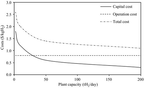
The total cost of the desalination plant is shown in Figure 6.38. The least expensive desalination method is HD at 7.5 $/(kg H2/day), which is considered in Configuration 1, and the technology with the highest initial cost (11.9 $/(kg H2/day)) is multistage flash desalination, which is used in Configuration 3. The total costs of VC and RO appear to be the same at 9.62 $/(kg H2/day), while the capital cost of multiple effect desalination is 11.7 $/(kg H2/day).

The energy efficiencies of the Cu–Cl cycle, desalination plant, and the overall system, including the Cu–Cl cycle and the desalination plant, are shown in Figure 6.39. The effect of the Cu–Cl cycle on the overall system is dominant, as the desalination plant uses much less energy than the Cu–Cl cycle. Thus, the efficiency of the Cu–Cl cycle and the overall system are very similar for each case. Configuration 1 exhibits a higher efficiency, as waste heat from the nuclear reactor (which is assumed to be “free”) is utilized in this option. In Configuration 2, recovered heat from the Cu–Cl cycle is used for desalination instead of internally, within the cycle. Thus, the Cu–Cl cycle and the overall system operate at lower efficiencies, as the effect of the cycle is very important on the overall system.
