
17
(b)
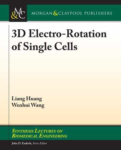
Flow
Cell (type A)
Cell (type B)
ITO
0°
180°
Flow
(d)(c)
Inlet 1
Computer
Function Generator
Video Microscope
Micropipette
PDMS Reservoi
r
Inlet 2
Electrode
Electrode
Partition
Micro Orifice
0°
Cell (type A)
Cell (type B)
Figure 1.11: DEP microuidic chip: (a) single-cell DEP capture chip [135], based on and used with
permission from the American Chemical Society; (b) single-cell DEP capture pairing chip [136],
based on and used with permission from the Royal Society of Chemistry; (c) cell electro-fusion chip
[137], based on and used with permission from AIP Publishing; and (d) single-cell electro-rotation
chip [138], based on and used with permission from the Royal Society of Chemistry.
1.3.4 ELECTRODE FABRICATION OF DEP CHIPS
At present, 2D planar electrodes have been widely used in microuidic chips, but 2D planar
electrode structure has limitations: the electric eld generated by the 2D planar electrode decays
quickly; the eective working regions are small; and the electric eld is non-uniform distributed in
the vertical direction. However, the thick electrodes can break through the limitations of the 2D
planar electrodes, and the electric eld generated by the thick electrodes can maintain uniformity
in the vertical direction, increase the spatial distribution range of the non-uniform electric eld, and
enlarge the working regions of DEP force.
1.3 DEP MICRODLUIDIC CHIPS

18
1. INTRODUCTION
e materials of planar electrodes are mainly metal materials. e processing generally in-
cludes photolithography, thin lm deposition, and chemical etching. ere are two types of planar
electrodes processing methods. (a) Sputter deposition (Figure 1.12(a)): (i) coating a layer of pho-
toresist on the substrate, and (ii) photolithography, (iii) depositing a layer of metal on the substrate
by a sputtering process, and (iv) nally degumming. is method is suitable for electrode materials
such as gold and platinum. (b) Metal layer chemical etching (Figure 1.12(b)): (i) depositing a layer
of metal on the insulating substrate by a sputtering process, (ii) spin coating a layer of photoresist
on the substrate, (iii) the photoresist is patterned using photolithography, (iv) etching the substrate,
the metal covered by the photoresist is retained, and (v) nally degumming. is method is suitable
for electrode materials such as indium tin oxide (ITO) and copper.
In view of the sputtering process, the thickness of planar electrode is from several nanometers
to several micrometers. It is not suitable to fabricate thick electrodes of several ten micrometers or
even several hundred micrometers. e main reason is that the sputtering speed is generally 100 Å/
min, and the use of a sputtering process for forming a thick electrode is not only time consuming
but also high cost.
(a)
(i) Spinning
(ii) Exposure &
Develop
(iii) Sputtering
(iv) Degumming
(b) (i) Sputtering
(ii) Spinning
(iii) Exposure &
Develop
(iv) Etching
(v) Degumming
Substrate Electrode Photoresist
Figure 1.12: 2D planar electrodes processing methods: (a) sputter deposition; and (b) metal layer
chemical etching.
e fabrication methods for thick electrodes currently used in microuidics can be divided
into the following.
1. Machining method, cutting a metal foil to form a thick electrode by machining, and
embedding the electrode into PDMS microchannel. Zeinali et al. used mechanical
processing to make thick electrodes and embedded them in the microchannel to
achieve cell sorting [139]. However, machining can only be done in a few hundred

19
micrometers. It is dicult to achieve a ner electrode structure, and the surface of the
electrode is rough.
2. Electroplating method, by depositing a metal on a 3D structure or depositing a metal
on a substrate having a 3D structure to form a thick electrode. Voldman et al. used a
plating method to fabricate a cylindrical 3D electrode [140], as shown in Figure 1.13
(a). e capture and release of single cells is achieved by the DEP force generated by
the 3D microelectrodes. However, the fabrication process is complex and high cost.
(a) (b)
B
-V +V
-V+V
PDMS
Liquid
Metal
Injection
Liquid
Metal
Electrodes
Fluidic
Channel
Flow
Figure 1.13: Microuidic on-chip thick-electrode fabrication method: (a) electroplating [140], used
with permission from the American Chemical Society; and(b) injection method [141], based on and
used with permission from the Royal Society of Chemistry.
3. Injection method, by solidifying a liquid or semi-solid conductive material into a
microchannel to form thick electrodes. ere are two types of structures according to
whether the electrodes are in contact with solution. One type is that the electrodes
contact with the solution. So et al. injected liquid metal through a syringe to make
thick electrodes as shown in Figure 1.13(b) [141]. Although this method can well
embed thick electrodes in the micro-channel, it needs to ensure good injection pre-
cision such that the conductive silver glue cures quickly. e other type is that the
electrodes don’t contact with the solution [142, 143]. And the form of DEP is called
cDEP (contactless-DEP). Shaee et al. designed a cDEP microchannel structure for
cell enrichment [144]. Electrolyte is used as electrodes in the electrode microchan-
nel, and electrical signal is applied to the electrolyte to generate a DEP force for cell
enrichment. is method is easier to prepare electrodes, but the biggest problem is
that the electrodes don’t contact with the solution, and a high voltage is required to
overcome the inuence of the insulating layer between the electrodes and the cell
1.3 DEP MICRODLUIDIC CHIPS
..................Content has been hidden....................
You can't read the all page of ebook, please click here login for view all page.