Chapter 5. 123D Make
123D Make is a program that helps you turn a 3D model into a real-world object. Unlike printing with a 3D printer, however, 123D Make turns all the parts of the model into a 2D plan: shapes that can be printed on and sliced from flat materials including wood, cardboard, plastics, and metal, and then assembled. This can be a great way to prototype designs. This program is best used with a laser cutter or ShopBot-style CNC machine.
After printing, you can use a laser cutter to slice the shapes out of your material by hand, or you can have them cut and delivered by a third-party service.
123D Make also creates an animated set of assembly instructions, based on the construction method you choose while preparing your model in the app.
123D Make is available for Mac, PC, iPhone, and iPad.
Getting Started
To get started with 123D Make, download the app from 123Dapp.com (Figure 5-1) and install it on your preferred platform.

Figure 5-1. Download 123D Make from 123Dapp.com
-
When you first open 123D Make, you are presented with several introductory slides that introduce the app’s different tools. Take a few seconds to click through these slides, and you’ll discover that many of them are similar to other apps in the 123D family.
-
Close the slideshow.
-
Now you are in the app’s main workspace (Figure 5-2): a blank screen, with a drop-down menu and tools for importing 3D models to the upper left, and a sign-in button at the upper right. Go ahead and sign in; this should be your first step when using any 123D program.

Figure 5-2. The 123D Make workspace
Drop-Down Menu
Click the downward-facing arrow inside a small circle at the upper left (Figure 5-3).

Figure 5-3. The 123D Make main menu
A menu will drop down that offers basic file commands; let’s take a look at each of these.
Open Example Shape
Offers a selection of preexisiting shapes such as a car, a flying saucer, a rhinoceros head, and more (Figure 5-4). These are fun and easy to play with, or to use as the basis for a new model. I have used the rocket shape to make many projects, such as this one: http://www.instructables.com/id/Rocket-Bookshelf/.

Figure 5-4. Example shapes make it easier to get started on a new model
Open
Open previous projects that you have made in 123D Make, or a project from the gallery (Figure 5-5), created by someone else.

Figure 5-5. Open a model from the 123D gallery
Save
Click on Save (Figure 5-6) and you will see two options.
The Save To My Projects option saves a file that holds the settings (not the cut file) that you have used in 123D Make to your 123D account.
The Save To My Computer option saves the 123D Make file to your own computer. It is a best practice to set up a project folder that holds the three essential elements of your project: your 3D model, your Make file, and your cut file.

Figure 5-6. Save project options in 123D Make
Save a Copy…
This option (Figure 5-7) saves a project in a separate file from the original project file. Useful for trying different ways of manufacturing or different material sizes.

Figure 5-7. Save copy options in 123D Make
Export Mesh
One of my favorite features, Export Mesh (Figure 5-8) allows you to save and export a mesh of your sliced or paneled model for 3D printing.
I use this a lot when trying to achieve a more geometric look to a design, as opposed to designing it all in flat planes.

Figure 5-8. The 123D Export Mesh menu
3D Print
Similar to Export Mesh, with the exception that this command sends your file directly to the Autodesk 3D print utility that sits within Meshmixer, where it is stitched up and made watertight. You must have Meshmixer installed in order for this command to work. If you don’t, you will be prompted to download the program.
Model Menu
This menu (Figure 5-9) appears right below the 123D Make logo and file menu, along the lefthand side of the workspace. It contains three buttons.

Manufacturing Settings Menu
Once you have a model open in the workspace, the Manufacturing Settings menu (Figure 5-10) appears below the Model menu.

Figure 5-10. The Manufacturing Settings menu in 123D Make
It includes a number of tools that allow you to customize the size of your model, the size of the flat material you intend to use, and more.
Gear Button
The gear button (Figure 5-11) contains various manufacturing settings that appear along the bottom and right side of the workspace.

Figure 5-11. The gear button, part of the Manufacturing Settings menu
Click the eyeball button to close these panels and go back to your model.
Pencil Button
This button (Figure 5-12) opens the Manufacturing Settings custom dialog box, where you can enter the settings for the particular material you plan to use, or even create a new material and related settings.

Figure 5-12. The result of clicking the Pencil button in the Manufacturing Settings menu
There are three options along the bottom of this menu: The single plus sign creates a new custom setting. The double plus sign creates a new custom setting based on a preexisting setting. The minus sign deletes a selected setting.
If you haven’t gotten your flat materials yet, you can make your best guesses, save the 123D Make file, and then alter them as needed once you have your material in hand.
This is important because material thickness can vary enough to prevent joints from fitting, or to create a distorted model.
Custom Menu
The Custom menu is to the left of the Pencil button (Figure 5-13).

Figure 5-13. The Custom menu in 123D Make
Use this drop-down menu to select from a number of preloaded settings for common flat materials, or the custom materials settings that you have created.
Note that after you have entered a custom material under the pencil icon, you must then select it with the drop-down menu to apply it to your part.
Object Size Options
You have a number of choices (Figure 5-14) in setting the size for your model.
Units
Choose inches, feet, millimeters, or centimeters, then enter the height, width, and length you intend for your real-world object. Be aware that if you choose to make an object several feet in length, 123D Make may need more time to process your model.
Original Size
If you designed your object to specific measurements, be sure to check this box!
Uniform Scale
Keeps your design constraints when sizing your object up or down.

Figure 5-14. The Object Size menu in 123D Make
Construction Technique Menu
The Construction Technique drop-down menu (Figure 5-15) offers a variety of options. Note that as you choose particular techniques and change their settings, to the right of your workspace the “sheets” and “parts count” also change. Generally speaking, the more sheets of material you need, the more expensive your object will be. The higher the number of parts, the more difficult, or at least time consuming, it will be to assemble the object.

Figure 5-15. The Construction Technique menu in 123D Make
Stacked Slices
Slices your object into flat numbered slices that can be stacked together to create the shape of your design. This is hugely popular for doing large scale sculptures and tabletop cardboard models.
You can also change the slice direction for these models by selecting the slice direction button below and toggling on the axis. This is also shown later in the chapter.
Click the Dowels option if you plan on using dowels as supports to pierce and stack the pieces of your object. Dowel shapes can be Square, Pencil, Round, Cross, Horizontal Slot, and Vertical Slot.
Be sure to enter the correct diameter for the dowels (or dowel-like objects) you intend to use in construction.
Figure 5-16 through Figure 5-19 show some incredible examples of what people have created with Stacked Slices.

Figure 5-16. By Jesse Harrington Au

Figure 5-17. By Evan Atherton

Figure 5-18. By Jesse Harrington Au

Figure 5-19. By Instructables member Damonite
Interlocked Slices
This technique creates a waffle-like pattern as shown in Figure 5-20. It works very well for building larger structures quickly, as well as for building custom shelving. Interlocked Slices seem to do better with more robust shapes such as a cube or human head. Interlocked Slices must be perpendicular—in other words, they need to be at 90-degree angles to each other as seen in Figure 5-21.

Figure 5-20. By ScaleFocus.nl

Figure 5-21. By Fabtextiles.org
Curve
Curve is one of the coolest ways of slicing your design. It creates a waffle pattern while following along a desired curve. To use the Curve command, select it from the drop-down menu and then select Slice Direction. You will see two axis options as well as a series of blue dots along a line.
As you can see in Figure 5-22, the original form is a lackluster shark.

Figure 5-22. A not-so-great shark
When we pull the blue arrow on the vertical axis about 90 degrees, the design starts to look a little more like a shark (Figure 5-23).

Figure 5-23. The curve helps create a more shark-like shape
By grabbing the blue circles and moving them to follow the curve of the shark’s back, the design becomes much more memorable (Figure 5-24).

Figure 5-24. Now we’re getting somewhere
Figure 5-25 shows a rad example of what is possible.

Figure 5-25. By Instructables member Penfoldplant
Radial Slices
The Radial Slices option is great for projects that are largely cylindrical in shape, such as my rocket ship bookshelf (Figure 5-26).

Figure 5-26. Rocket ship bookshelf by Jesse Harrington Au
Folded Panels
The Folded Panels option is by far the most versatile of the slicing methods available in 123D Make. Its uses have ranged from creating a 12-foot-tall cardboard Trojan horse, to creative stuffed animals, to 3D prints that have a paneled look. However, if you use Folded Panels to create larger forms, the final object will lack any support structure; that will need to be added manually.
As you can imagine, this is bit trickier than other construction techniques. Luckily, the app intelligently labels each piece like a puzzle to assist you in fabrication. Think “insert z-09 to adjacent piece z-10.” Not impossible, but takes a bit of tinkering before you begin. A few examples are shown in Figures 5-27, 5-28, and 5-29.

Figure 5-27. Folded panels before 3D printing

Figure 5-28. Printed model created using folded panels

Figure 5-29. Another cool example of the folded panel model
Vertex Count
This establishes the number of edges each individual piece can have. The higher your count, the better resolution your final piece will have, but there are trade-offs. For example, if your vertex count is 500, the printed pieces would create an object very close to your original 3D model—but you would have a difficult time assembling it.
Add/Remove Seams
This option functions just as it sounds: when in folded panel mode, this command will add or remove seams from your model (Figure 5-30).

Figure 5-30. Removing seams from a skull
Joint Type
Your joint type will determine how you put your pieces together after you cut them out. This is pivotal to your success. You should deeply consider what material you will be using and how you will be cutting out the shapes before making the final decision on joint type. You can always go back and change it, but it might cost you a lot of cutting time and some valuable materials. For instance, if I know that I am using cardboard to construct, I prefer using the rivet technique and then using zip ties in place of rivets. You can also use this method for Metal, unless you are welding; in that case you can use Seam.
Puzzle
Using the Puzzle selection will turn your connections into puzzle pieces. This is not a great way to make a 3D model, but it is a really fun way to make a 2.5D model—in other words, something more flat than truly 3D.
Figure 5-31 shows what the pieces look like.

Figure 5-31. Puzzle pieces
Rivet
Creates a tab with holes on one side and corresponding holes with no tab on the other so the joint is tight together. Great for using zip ties in cardboard! This is what was used in the Yeti sculpture in Figure 5-32 and also in the large Trojan horse sculpture shown in Figure 5-33.

Figure 5-32. By Yukonstruct

Figure 5-33. by Instructables member Penfoldplant
Slice Distribution
Slice Distribution determines how many slices you have in each direction (Figure 5-35). So, if you choose interlocked, curve, or radial, you will have two directions of slicing. You can alter your distribution to add more slices to a direction. If you only choose one slice, you will see that there is only one piece of material in that direction.

Figure 5-35. Slicing a head by count
Choose “By Count” or “By Distance.”
- 1st Axis
-
First angle of your slices. Toggle up or down to determine the amount of slicing. This will either add pieces or subtract them from your model. Here I have changed the 1st Axis to 20 (Figure 5-36).

Figure 5-36. Slicing a head by distance
- 2nd Axis
-
Second angle of your slices. Toggle as above. This time I changed it by measurement and set it at .175, which is about the size of a piece of cardboard between each piece (Figure 5-37).

Figure 5-37. Choosing a second angle of slicing
- Notch Factor
-
Creates a chamfer (angle cut) on the corners of each finger. This will help you greatly when putting things together in real life. Right angles on laser cut cardboard will look pretty but will make all of your hair fall out when trying to put it together.
- Notch Angle
-
Determines the angle of the chamfer used at the end of each finger.
- Relief Type
-
Changes the base of each notch. The only real options here are square or dog bone. Dog bone is useful with any interlocked construction technique, as it allows you to use thicker materials, as well as more advanced manufacturing techniques such as CNC routing. This is because CNC routers have cylindrical cutting bits, and cylinders cannot make nice squared ends. So the dog bone shape allows some room to make sure your pieces that were cut out on a router will sit flush to one another.
Slice Direction
Slice Direction is going to determine which angle your slices will follow. It is a bit tough to explain, so take a look at Figure 5-38 through Figure 5-40. Basically this option determines in which direction(s) you will be slicing your model. The easiest case for this would be stacked slices. If you choose to do stacked slices, 123D Make will automatically slice your model in the vertical axis (i.e., the z-axis). When you alter the slice direction, you will be moving from the vertical toward the x or y, thus creating a more dynamic look to your piece.

Figure 5-38. Locking in a slice direction
You can use this for any slicing option with the exception of folded panels. Folded panels only sit on the surface of your model and do not technically slice your model.
To use Slice Direction, click on the icon next to the command for Slice Direction on the left side menu. Then drag that blue arrow in the desired direction (Figure 5-39).

Figure 5-39. Drag the blue arrow…
You can see how it adjusts the direction that it is creating your stacked slices (Figure 5-40).

Figure 5-40. ...to adjust the direction of a slice
Modify Form
Modify Form allows you alter your model in ways that render it easier to assemble after printing. The options include:
- Hollow
-
Makes your solid object hollow. This is a super useful feature that will save you material and expense. It can also make an object more lightweight, or even floatable!
- Thicken
-
Makes a part thicker. If you find that areas of your part are a bit too thin for practical manufacturing, this tool will help you correct that.
- Shrinkwrap
-
Very similar to Thicken, Shrinkwrap adds a thicker skin to your part. For example, if your model includes lots of holes, Shrinkwrap will plug them up.
Figure 5-41 through Figure 5-43 is a ridiculous example that illustrates the point.

Figure 5-41. Normal model of a skull

Figure 5-42. The model preview using the thicken tool
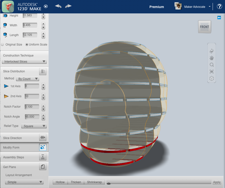
Figure 5-43. The finished model after using the Shrinkwrap tool
Assembly Steps
This tool will literally show you the best order of steps for assembling your model. When selected, click on the left- or right-pointing arrows on the bottom right side of your screen. This will walk you through your construction steps begining with the first two pieces that you should connect and in what order to add them. This is super helpful when choosing the interlocked construction technique, as it can get a bit tricky, even though everything is numbered. If you click on the left arrow, it will take you back a step, while the right arrow brings you forward.
Get Plans
You guessed it, this is how you actually leave the digital world and enter the physical. This takes your drawings that are shown on the right side of the screen and turns them into vectors that your cutting tool will follow in order to make each piece.
Options include EPS, DXF, or PDF. If choosing DXF, be sure to indicate what measurements you would like the resulting file to use, and be sure to clarify if you want the resulting file to use English or metric measurements (many cutters only have metric software). Then press the Export button to save your file in that format.
Note
You will want to choose the Nested option under Layout Arrangement to save material and significantly shorten cutting time. If you are using a laser to cut out your objects, you can open up your DXF, EPS, or PDF file in your favorite vector design program like Corel or Adobe Illusrator and move your pieces to be almost touching. The reason for this is that lasers are precise enough that you can save a lot of material by moving your objects very close together. You would not want to do this on a CNC router unless you spaced them apart based on your router bit. If you are using an 1/8th-inch cutting bit and your objects are only 1/16th of an inch apart, then you will be cutting into your parts while cutting out others.
OK, now that you know how to get around 123D Make, you’ll really appreciate some of the amazing things that people have created with it (see Figure 5-44 though Figure 5-47)!
You can find more information about these projects, including build instructions, by checking out Instructables.com.

Figure 5-44. Solar hot-water heater

Figure 5-45. Strata Bench by member ADintheStudio

Figure 5-46. Awesome Lamp by member PATHfab
