Chapter 4. 123D Design
123D Design is computer-aided design software that allows you to create precise, even complicated parts for models and objects of all sizes. This program totally rocks at mechanical designs from small to house-sized, such as a housing for your Raspberry Pi (Figure 4-1) or a prototype of your next playground structure (Figure 4-2).

Figure 4-1. A model for a Raspberry Pi enclosure

Figure 4-2. A model for a backyard play structure
You can import any .stl or .obj file into 123D Design. You also have access to thousands of existing models in the 123D online gallery, which you can access via the Open File command as long as you are connected to the Internet at the time.
Figure 4-3 and Figure 4-4 show some killer examples of things that users have built with 123D Design, from quadcopter housings to Iron Man’s armor.

Figure 4-3. Some examples of models created with 123D Design

Figure 4-4. More examples of models created using 123D Design
Download and Set Up
If you have not yet done so, download 123D Design from 123Dapp.com (Figure 4-5) and install it on your computer. As this book goes to print, the available versions are PC, Mac, and iPad.

Figure 4-5. The 123D Design download page on 123Dapp.com
The first time you open the program, you’ll be presented with a welcome screen—actually, the beginning of a slideshow of Quick Start Tips (Figure 4-6). Take a minute to look over these nine slides to get familiar with 123D Design.

Figure 4-6. The 123D Design welcome screen
When you’re done, you can sign in to 123D Design using your existing 123D account, create a new one, or simply click the big button to Start a New Project (in which case, you can always sign in to Design later on).
Getting Around
While we are still playing around and getting to know the app, let’s practice using the three-button mouse to move around the space.
Roll the middle scroll wheel to zoom in and out (Figure 4-7).

Figure 4-7. Roll the middle scroll wheel to zoom to and away from the object
Hold the scroll wheel down and move the mouse to pan (Figure 4-8).

Figure 4-8. Panning moves your view horizontally along the object
Right click and hold to orbit (Figure 4-9).

Figure 4-9. Right click and hold down to circle around the object
Getting Started: Playing with Blocks
Creating in this program is essentially a simple two-step process repeated over and over again (Figure 4-10):
-
Make a sketch, or create a two-dimensional shape.
-
Apply an action or feature such as “extrude” or “revolve” to turn that sketch into a three-dimensional shape.

Figure 4-10. Making a model in 123D Design is essentially a two-step process
That’s it! With this knowledge alone (plus a bit of practice) you should be able to build almost anything with 123D Design.
Before reading the rest of the chapter, open up 123D Design and let’s give this a try.
Step 1: Create a Rectangle on the Main Plane
-
Hover your arrow over the top menu bar until you see the yellow Sketch prompt appear (Figure 4-11).

Figure 4-11. Sketch prompt
-
Choose Sketch Rectangle (Figure 4-12).

Figure 4-12. Choose the Sketch Rectangle option
-
Follow the prompt to click on the big blue grid (Figure 4-13).

Figure 4-13. Click on blue grid
-
Click once to start the rectangle (Figure 4-14).

Figure 4-14. Start the rectangle
-
Move your cursor and click again to stop (Figure 4-15).

Figure 4-15. Click to stop
-
Select the green checkbox to exit (Figure 4-16).

Figure 4-16. Click the green box to exit
Step 2: Extrude the Rectangle into a 3D Object
-
Hover the cursor over the top menu bar and select Construct (Figure 4-17).

Figure 4-17. Select the Construct option
-
Then select Extrude (Figure 4-18).

Figure 4-18. Select the Extrude option
-
Follow the prompts to select your 2D rectangle (Figure 4-19), and then use the arrow by clicking and holding while moving your cursor (Figure 4-20).

Figure 4-19. Select your rectangle

Figure 4-20. Click and hold
-
Release, and you now have a box (Figure 4-21).

Figure 4-21. Your new box!
Congratulations—you are now a CAD modeler!
Take a few minutes right now to practice these two steps a few more times, using various sketch shapes and construction commands.
Now, let’s go through the details so we can become experts.
Step 3: Make Changes to the Model
You have a box. How do you select the elements of the box that you would like to alter?
-
To select an object, simply click on it (Figure 4-22).

Figure 4-22. Click to select
-
To select a specific face, edge, or corner, click again on the element you wish to select (Figure 4-23).

Figure 4-23. Click the element
-
To alter, hover over the gear icon and select a method to alter your selection (Figure 4-24).

Figure 4-24. Select a method to alter
Spend a few minutes playing around here, to see if you can replicate the images in Figures 4-25, 4-26, and 4-27.

Figure 4-25. Test Object A

Figure 4-26. Test Object B
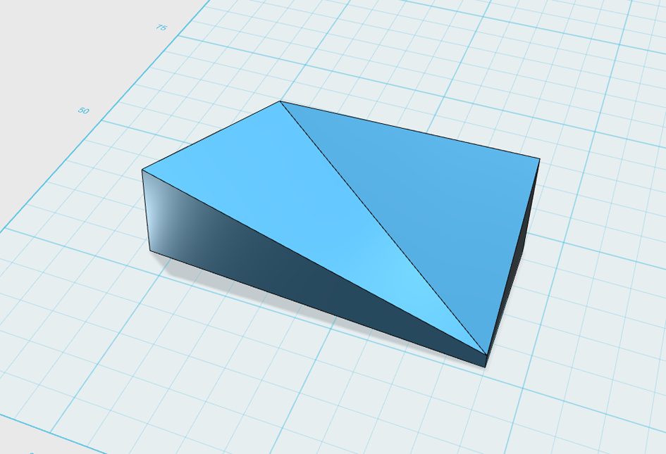
Figure 4-27. Test Object C
The Parts Library
On the righthand side of the interface is a library full of premade parts that you can utilize for your creations. This library, which is regularly updated, includes things such as lighting fixtures, gears, playground parts, hand tools, and models based around science. To access them, look all the way over to the right, where you’ll see a thin, blue vertical rectangle with a white arrow in it. Click and drag it to the left.
This is also a great way for you to design quickly so that you are not re-creating parts that have already been modeled before, such as screws, bolts, and pulleys.
Let’s quickly build a model of a molecule—a collection of atoms and their chemical bonds, represented here by balls and sticks—before we begin modeling from scratch.
Use the drop-down menu and select the Science category.
Pull one of the atoms into the interface by clicking on it and dragging it over near the grid. Do the same with a bond (Figure 4-28).

Figure 4-28. Place an atom and bond on the interface
Choose the snap tool from the end of the toolbar menu. Follow the prompts to select an end circle of the bond, and then an end circle of an atom (Figure 4-29 and Figure 4-30, respectively).

Figure 4-29. Select a bond and an atom

Figure 4-30. Attach!
Continue adding bonds and atoms until you form a molecule (Figure 4-31).

Figure 4-31. A molecule (or futuristic space station)
If you select the molecule, go to grouping and then select Ungroup All. You can then add different materials to each piece of the structure.
Try this with other parts in the library. It’s a fun, easy way to learn how to navigate the program.
Now, let’s get into the thick of it!
Start Building from Scratch
When you begin a new project or reopen an existing project, you’ll be working on the main plane (Figure 4-32). This big blue grid is the surface or workspace where you place objects and sketches, and manipulate them to create and fine-tune your design.

Figure 4-32. The main plane in 123D Design
You can think of the main plane simply as a piece of stiff paper that you can draw upon.
Let’s get familiar with the menu options across the top of the 123D workspace, above the main plane (Figure 4-33). The following sections describe each of these options more fully.
Main Menu

Figure 4-33. The 123D Design main menu
Open
Opens a preexisting file. You can also use this option to choose one of the thousands of models in the 123D online gallery.
Insert
Imports STL files from your online projects space or your computer into the current file.
You can also insert objects from the 123D Gallery, as well as some example files.
Import SVG…
Imports SVG files either as a sketch or a solid. These can be vector files you find online or create in other programs such as Adobe Illustrator, Corel Draw, or Inkscape, or higher-end design programs such as Autodesk Inventor, SolidWorks, or Rhino. Once imported, you can manipulate these files in 123D Design.
Save…
Saves your sketch, either in the cloud or to your computer.
Save a Copy…
Saves the current version of your design while keeping the original intact. Use this as a way to do rapid iterations. You have two options: Save “to my projects,” which will save your project to your 123D account in the cloud; and “to my computer,” which saves your project offline, to your own hard drive.
Export…
Save to STL, SAT, or create a 2D layout. STL files are the default file type for 3D CAD work. A 2D layout is historically a line drawing with measurements. In 123D, this option translates the file for you and saves it inside your projects area on 123Dapp.com. 2D layouts are very helpful when you’re building something and need a drawing file. (It may take a few minutes for the drawing to appear, so be patient.)
Send To…
Options include:
-
123D Make, where you can slice it up into flat pieces for fabrication.
-
CNC utility, which you can use to cut your file subtractively with a ShopBot or other CNC router device.
-
3D print service, which opens your file on 123Dapp.com so you can choose between various services that can print your object into reality: 3D Hubs, i.materialise, Sculpteo, and Shapeways.
The Ribbon Menu
The ribbon, or control panel (Figure 4-34), contains tools that allow you to create and alter shapes and volumes located on the main plane.

Figure 4-34. The ribbon, or control panel
Undo/Redo
The left- and right-facing curved arrows (Figure 4-35) allow you to Undo and Redo actions, respectively.

Figure 4-35. The Undo and Redo arrows in 123D Design
Transform
The icon of a cube inside a dotted-line square (Figure 4-36) contains Transform tools you can use to move, rotate, and scale your object up or down. But you need to have an object in the workspace to transform! So let’s skip these tools for the moment.

Figure 4-36. Transform tools
Primitives
Primitives are common shapes, such as a box or torus, that you can drop on the plane (Figure 4-37). Primitives save you from having to create these shapes from scratch over and over again as you apply them to an object. Click the shape you wish to use, use your mouse to move it to the plane, and then click your mouse to place it down. Also note that you can enter specific values for height, width, radius, and so on.

Figure 4-37. The primitives menu
Note
Right-click with your mouse to move the main plane around and see different views of the objects. Zoom in and out by turning the mouse’s scroll wheel. Pan (move up and down) the main plane by clicking and holding the scroll wheel while moving the mouse.
Sketch
Creating a sketch in software is similar to creating one using pen and paper. In both cases, you need something to draw on and something to draw with.
In 123D Design, the something to draw on is the main plane, as well as any flat surface on the main plane, such as the side of a cube.
The things to draw with are the Sketch tools. These come in various shapes and sizes and can be effective in different ways, depending on the complexity of the object you’re making. You can choose to create common shapes such as rectangles, circles, lines, or splines, and enter specific values for their dimensions.
When you’re making a sketch, be sure to include two things:
- Measurements
-
Even if you can only make a best guess at the final dimensions, it’s a good idea to include measurements in your sketch file. Try to keep them whole numbers or one place past the decimal. More complicated numbers will be more challenging to alter later, or to match up with if you need to make another object fit into the one you’re working on.
- Closed shapes
-
Any shape you create with your sketch has to be devoid of holes and gaps in order for you to turn it into a 3D solid.
To start sketching, select the Sketch toolkit from the action tools. Here you’ll find common tools such as line, rectangle, circle, and spline (Figure 4-38).

Figure 4-38. The Sketch menu
When sketching, keep your view cube turned so that you’re looking at the sketch straight on. If you don’t, you’ll have a skewed perspective that will make it harder to get the shape you want as you work on the design.
Rectangle
The Rectangle is one of the tools you’ll use the most as you’re designing. To use it:
-
Select the Rectangle tool from the Sketch toolkit (Figure 4-39).

Figure 4-39. The Rectangle tool in the Sketch toolkit
-
Select your sketch plane: the main plane or the face of an object.
-
Click once in the place where you’d like one corner of the rectangle to be. Move your mouse until the rectangle is the size you want, then click again to finish the shape (Figure 4-40).
Note
If you want to make a rectangle of a specific size, hit the Tab key on your keypad and toggle between width and length dimensions.

Figure 4-40. A sketch of a rectangle on the main plane
You can also use the Rectangle tool to generate more complex shapes by layering different rectangles on top of each other. You can then add your choice of feature to create your 3D shape.
If you need to clean up the design, use the Trim tool (Figure 4-41) in the Sketch toolkit to trim overlapping lines and create a smooth shape.

Figure 4-41. The Trim tool
But you don’t have to: 123D Design allows you to create a complex 3D shape even if it’s not perfectly trimmed.
You can extrude an overlapped shape by selecting which parts you want or don’t want extruded.
Note
You can also use the Rectangle tool to set up basic parameters for your complex shape—for example, to keep your design within a certain number of inches without going beyond that measurement.
Circle
-
Select the Circle tool from the Sketch toolkit (Figure 4-42).

Figure 4-42. The Circle tool
-
Click on the main plane (the blue grid) where you’d like the center point of the circle to be (Figure 4-43).

Figure 4-43. Click where center of the circle should be
-
Move your mouse away from the center point until the circle is the size you wish, and then click again to “set” that size. You can also type a specific dimension into the dialog box and then press the Enter key (Figure 4-44).

Figure 4-44. Set the size of the circle
-
Click the checkmark to finish sketching your circle.
Note
You can use the Circle and Rectangle tools together to make a whole lot of different designs. For example, you can add rounded corners to a rectangle, or create a rectangular shape with a circular shape cut out of it.
Ellipse
The Ellipse tool makes it easy to add a bit of an arc to a surface. You may find yourself using this tool frequently. The Ellipse tool is also helpful when doing the loft operation (shown below).
To use the Ellipse tool:
-
Select the Ellipse tool from the Sketch toolkit (Figure 4-45).

Figure 4-45. The Ellipse tool
-
Click the plane where you want the center of the ellipse to be (Figure 4-46).

Figure 4-46. Click where the center of the ellipse should be
-
Click again to designate the height or length of the ellipse (Figure 4-47).

Figure 4-47. Set the first dimension of the ellipse
-
Click again to designate the remaining dimension (Figure 4-48).

Figure 4-48. Set the other dimension of the ellipse
Polygon
The Polygon tool allows you to create multisided shapes.
To use the tool:
-
Select the Polygon tool from the Sketch toolkit (Figure 4-49).

Figure 4-49. The Polygon tool
-
Click on your sketching surface where you want the center of the polygon to be.
-
Move the mouse to the desired radius and click again.
-
To change the number of sides, press the Tab key and toggle between dialog boxes, and type in the number of sides you want. Then click again to end the sketch.
Note
Need to make a perfect triangle? Use the Polygon tool.
Polyline
Use the Polyline tool to create line segments that make up shapes. A line segment consists of a straight or curved line that joins two points. Once you’ve created a shape, you can apply a feature, such as extrusion or loft, to the shape you’ve created. The Polyline tool, a well as all other sketching tools, allows you to add a third dimension to your sketch and make precise shapes that can be fit together.
To use the Polyline tool:
-
Choose the Polyline tool from the Sketch toolkit (Figure 4-50).

Figure 4-50. The Polyline tool
-
Click once where you’d like your line to start. Release the mouse, move your mouse to the location where you want your line to end, and click again.
-
To make multiple segments, move the mouse and click again.
-
To create an arc using the Polyline tool, hold down the left mouse button and drag, creating the radius of the arc.
OK, now it’s time to use the skills you’ve just learned to build something fairly simple.
Spline
Use the Spline tool when you want to make a freeform organic shape to extrude or revolve.
Think of splines this way: imagine that you have a board with nails in it and a string that you’re going to thread around the nails to make curves. Each click you make in the sketching space is like putting a nail in the board, and the software automatically curves the string around it.
You can end a spline either by taking it back to its original starting point or by right-clicking or double-clicking.
Splines allow you put fun and crazy curves into your shapes—and useful curves, such as those in the body of a guitar (see Figures 4-52, 4-53, and 4-54).

Figure 4-52. A combination of simple splines

Figure 4-53. With the segments closed, the splines become a shape

Figure 4-54. By applying extrusion tools and other detailing, the shape becomes three dimensional
To use the Spline tool:
-
Select the Spline tool from the Sketch toolkit (Figure 4-55).

Figure 4-55. Select the Spline tool
-
Click in the main plane to create your first point (Figure 4-56).

Figure 4-56. Create the first point
-
As shown in Figure 4-57, move your mouse and click again to create your second point. (This will show up as a straight segment—that’s OK.)

Figure 4-57. Create the second point
-
Move your mouse and click once more. You will now see the curve (Figure 4-58).

Figure 4-58. Move the mouse and click to see the curve
-
Continue clicking to make your desired shape (Figure 4-59).

Figure 4-59. Another click expands the shape
Note
The closer together your anchor points are, the tighter the curve of the spline will be.
-
If you’re making an open shape, you can either double-click to end the sketch and then hit Escape, or click the checkbox to exit your sketch.
-
If you’re making a closed shape, you’ll see that a blue box appears when you get back to your starting point (Figure 4-60).

Figure 4-60. Start the closed shape with the first click
-
When you’ve created your spline, you can still tweak it by clicking and dragging on anchor points until you’ve got your desired shape.
Warning
Do not attempt to trace a complex shape by putting down thousands of spline points. You’ll likely crash the program and then regret that you wasted so much time. Instead, build your shape using a combination of primitives and splines.
Like rectangles and circles, splines are most useful in conjunction with other shapes and geometry features (Figure 4-61 and Figure 4-62).

Figure 4-61. Which primitives have been combined with splines to create this shape?

Figure 4-62. Here, simple circles, cylinders, and splines add up to a complex 3D object
Two-Point Arc
The Two-Point Arc tool allows you to define a curve by setting two points and adjusting the amount of curvature between them.
-
Select the Two-Point Arc tool from the Sketch toolkit (Figure 4-63).

Figure 4-63. An arc of two points
-
Click on your grid or solid surface to begin sketching.
-
Click once where you’d like the center of your arc to be (Figure 4-64).

Figure 4-64. The center of the arc of two points
-
Click again or type in your radius to specify where you’d like the arc to start (Figure 4-65).

Figure 4-65. The radius of the arc of two points
-
Move the mouse and click again to define the end point of your arc (Figure 4-66).

Figure 4-66. The end of the arc of two points
-
And now you have a two-point arc! You can begin another arc on the plane, or click the checkmark to exit the Two-Point Arc tool (Figure 4-67).

Figure 4-67. Exiting the arc of two points
Three-Point Arc
The Three-Point Arc tool allows you to define a curve by setting three points (two end points and a middle). The software then automatically sets the amount of curvature between them.
-
Select the Three-Point Arc tool from the Sketch toolkit (Figure 4-68).

Figure 4-68. An arc of three points
-
Click on the main plane, a Face, or a Solid to start sketching.
-
Click on the sketching area where you want your arc to begin (Figure 4-69).

Figure 4-69. The start of the arc of three points
-
Click again where you want your arc to end (Figure 4-70).
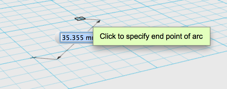
Figure 4-70. The end of the arc of three points
-
Click to select the third point (Figure 4-71).

Figure 4-71. The third point of the arc of three points
-
You’ve created a three-point arc. Now you can begin a new arc, or click the checkmark to exit the three-point arc tool (Figure 4-72).
Figure 4-72. Exiting the arc of three points
Fillet: Adding a Rounded Corner
You can round the edges of an object with an operation called a fillet. In CAD lingo, this word is pronounced as it’s written, saying the t at the end (experienced CAD users can always spot a newbie when they hear this term pronounced as if it’s a piece of fish).
You can round edges while in Sketch or 3D Modeling mode. It depends on what order of operations you’re most comfortable with, and what will work best for your model.
To fillet:
-
Choose the Fillet tool from the Sketch toolkit (Figure 4-73).

Figure 4-73. Choose Fillet
-
Select the sketch you want to edit, and then select one line (Figure 4-74) followed by another that you want to round (Figure 4-75). Or, select a corner that you wish to round.

Figure 4-74. Pick the first of two lines to round with the Fillet tool

Figure 4-75. Then pick the next line
-
You can enter a specific radius (Figure 4-76), or push and pull the arrow (Figure 4-77) to make your fillet, using the Fillet Radius box that comes up when you select the Fillet tool.

Figure 4-76. Enter a specific radius if desired

Figure 4-77. Or, push/pull the arrow to curve the edge
Trim
The Trim tool is very useful when creating complex shapes, or if you need an exact shape with a complex curve in it. It allows you to remove external material from your sketch. To use the Trim tool, follow these instructions:
-
Choose the Trim tool (Figure 4-78) from the Sketch toolkit.
Figure 4-78. The Trim tool
-
Click the sketch you wish to edit (Figure 4-79). The sketch must contain some overlapping lines.

Figure 4-79. Select the sketch you want to trim
-
Hover over the overlapping line or lines you want to trim, and you’ll see them turn red (Figure 4-80).

Figure 4-80. The line to be trimmed turns red
-
Click on the red line to remove it (Figure 4-81).

Figure 4-81. Remove the red line with a click
Extend
Extending a sketch is a reliable way to make sure that your sketch connects to the next intersecting line.
-
Select the Extend tool (Figure 4-82) from the Sketch toolkit.

Figure 4-82. The Extend tool
-
Select the sketch that you want to work with (Figure 4-83).

Figure 4-83. Select the sketch that you wish to extend
-
Select the arch within the sketch that you want to extend (Figure 4-84). A red line will appear (Figure 4-85) indicating where your sketch will extend to.

Figure 4-84. Select the arch that you wish to extend

Figure 4-85. The red line shows how far the sketch will extend
-
Click the checkbox or hit the Enter key and the shape will become solid (Figure 4-86).

Figure 4-86. An extended sketch.
Offset
Offsetting lets you create thicker walls on objects with more complex shapes. In some situations, you can also do this with the Shell tool.
To use the Offset tool:
-
Select the Offset tool from the Sketch toolkit (Figure 4-87).

Figure 4-87. The Offset tool
-
Select the sketch that you want to offset (Figure 4-88).

Figure 4-88. Select the sketch to be offset
-
Hover your mouse over a line on that sketch.
-
Enter your measurement (estimate if you’re not sure), and then select the green check button or press the Enter key, and your offset will be finished (Figure 4-89).

Figure 4-89. An ellipse with an offset
Construct
This set of tools is used to turn 2D shapes (created with Sketch tools) into 3D shapes, also called solids.
Extrude
Use the Extrude feature when you want to model a cube or shape that starts with two flat sides.
Figure 4-90 and Figure 4-91 show just a few examples of what you can do with the Extrude tool, which you’ll find yourself using almost as much as the sketching tools.
Extrusion means to take a 2D sketch and add that third dimension that turns it into an object. Shapes can be extruded up, down, or outward, according to the measurements you desire.

Figure 4-90. A flat, 2D image

Figure 4-91. The flat image, extruded into the third dimension
One particularly useful aspect of the Extrude tool is that it allows you to create models from premade parts. You can make a premade part more complex by sketching on an already-extruded surface and then extruding what you’ve sketched. In this way, you can add new surfaces to the object.
You can also extrude in the opposite direction to create pockets or holes. This process is called cutting, because it cuts away surface area from the solid shape.
Here are the basics of using the Extrude tool:
-
Start with a sketch (Figure 4-92).

Figure 4-92. Start the extrusion process
-
Select the Extrude tool, shown in Figure 4-93, from the Construct toolkit.

Figure 4-93. The Extrude tool
-
Select the sketch, or you can select the Extrude tool from the gear symbol that appears once you’ve selected the sketch.
-
When you select the sketch, a little white arrow will appear, along with a dialog box. As with other tools, you can either type in specific measurements or click and drag the arrow until you have the size you want. When you’re satisfied, hit the Enter key (Figure 4-94).
While you’re still in the Extrude tool, you’ll see a circle on an arc. You can click the circle and drag it to create a draft angle, altering the width of the top of the part. This comes in handy when making injection-molded parts. If you’re planning to mass-produce a plastic injection-molded object, you’ll want to use a draft angle of 2%.

Figure 4-94. The selected sketch
If you want to create holes or pockets in your object, begin with a sketch on a flat surface. Select the Sketch tool and then select Flat Surface. Once you’re done sketching, select the Extrude tool and pull it back through the part (Figure 4-95). You’ll see the extrusion previewed in red, and you’ll also see the little icon in the drop-down menu change from the join icon to the cut icon.

Figure 4-95. The extruded sketch
Sweep
Use Sweep when you want to make something like a piece of tubing or bent pipe.
Sweep is an efficient way to build more complex designs that involve tubing, such as a bicycle frame. To create a sweep, you need:
-
A profile or shape for the tube (this is the shape that you would see if you looked at the tube from an open end)
-
A path for the profile to follow
These are shown in Figure 4-96.

Figure 4-96. The two sketches you will need to create for this tool on flat grid
You’ll need to move your sketch so that it’s perpendicular to the sketch of your path. To do this, first select the profile sketch. In the pop-up gear menu, select Move, and use the orbit controls to toggle your sketch into place (Figure 4-97).
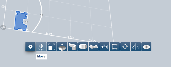
Figure 4-97. Use the move tool to make your flat profile sketch perpendicular to your path using the Move tool
Now, select the Sweep tool, shown in Figure 4-98, from the Construct menu.

Figure 4-98. The Sweep tool
A dialog box will appear, asking you to select a profile to sweep and then select a path to sweep that profile down (Figure 4-99).

Figure 4-99. The profile sketch perpendicular to your path sketch
Figure 4-100 shows the result. You’ll find Sweep very helpful when working on projects that have cords or bent tubing.

Figure 4-100. Finished preview of the Sweep tool
Revolve
Use Revolve when you want to make a part like a bowl, a cup, or a chess piece.
To use the Revolve tool, your sketch must contain a shape you want to revolve and an axis that you want it to revolve around. With simple objects like bottle or cup shapes, you can create a vertical line that will become the axis your sketch will rotate on.
This chess piece is an example of a shape that involves a closed revolve. To make it, create an outline of one-half of the final piece. Remember that in 123D Design you can have overlapping shapes and you can select multiple sketches for the same feature.
Once you’ve made your sketch, select the Revolve tool, shown in Figure 4-101, from the Construct toolkit.

Figure 4-101. The Revolve tool
When you select the Revolve feature, a little dialog box will appear. It’s always a good idea to have a look at these dialog boxes to see what they’re asking for. In this case, it’s asking you to choose the profile you’d like to rotate (Figure 4-102).

Figure 4-102. Choose the profile to rotate
You’ll see your selected profile highlighted in blue. Next, select the Axis button in the pop-up menu dialog box (Figure 4-103). This is how you choose the line that will be the axis.
In the dialog box, type the amount that you’d like to rotate the profile. In most cases (this one included), you’ll want to rotate through 360 degrees.

Figure 4-103. Select the Axis button to rotate the profile on its axis
Figure 4-104 shows the final result after revolving a profile on an attached axis. The holes were added after the revolve.

Figure 4-104. When the profile of a shape is revolved around a central axis, the result is a 3D object
You can also revolve a shape around an axis that isn’t attached to the profile. For example, see Figure 4-105 and Figure 4-106.

Figure 4-105. Note that the axis is detached and is several units to the left of the profile

Figure 4-106. Revolving a profile around a detached axis creates an opening in the final shape
Loft
Use Loft when you want to create a complex shape based on multiple profiles or sections.
Lofting is the favored choice for product designers, especially those looking to make ergonomic shapes. For example, let’s say you need a handle for an ice axe, which is a rather complex shape (Figure 4-107).

Figure 4-107. How to make a complex shape by combining profiles
This operation is called lofting because you literally loft one sketch up to another. It may sound complex, but it’s really quite simple. You start with a profile for the beginning of the loft, and then choose a second profile that will guide the first profile to the place you want it to go. Lofting is also a chance to use some projected geometry.
To get started, you’ll need to create a series of sketches based roughly on an original. I suggest starting with a basic shape by copying and pasting it to set up your planes. You can do this by using Ctrl-C and Ctrl-V on any closed sketch (Figure 4-108).

Figure 4-108. Start with a circle
Be sure that your closed sketch doesn’t have overlapping lines. When a loft doesn’t work, it’s usually because the sketch has lines that are overlapping or aren’t connected (and therefore the sketch isn’t closed).
Let’s try it:
Sketch a circle. Then copy and paste your circle a few times. With each paste, drag the circle vertically to somewhere else in the sketching space (Figure 4-109).

Figure 4-109. Copy and paste several sketches of a circle vertically in the main plane
For this particular example, I offset each circle with an ellipse, giving the shape the characteristics of a hand grip (Figure 4-110).

Figure 4-110. Sketches of circles alternating with ellipses
In this scenario, as in most lofting scenarios, you’re going to loft more than one sketch to another. To do this, hold down the Shift key and select each sketch, in order. In other words, start at one end and work your way toward the other (Figure 4-111).

Figure 4-111. Hold down the Shift key and select each sketch in order, either from top to bottom or bottom to top
With all the shapes selected, click on the Loft tool from the pop-up menu or the Construct toolbar (Figure 4-112).

Figure 4-112. Click on the Loft tool after all the shapes are selected
Now you can see the result: almost like magic, the sketches are connected into a whole. If you are not happy with the result, simply undo or Ctrl-Z each step, change your sketches, and then repeat the Loft command.
Here is the final result of lofting my stack of circles and ellipses, before (Figure 4-113) and after (Figure 4-114) I added some texture.

Figure 4-113. The lofted stack of circles and ellipses

Figure 4-114. With the addition of texture, the lofted object begins to resemble a handgrip
Modify
Use the tools in Modify to build out, refine, and add gross details to sketches and models.
Fillet
As with the sketch fillet tool earlier, fillets should always be added last, as they can turn a boring straightforward design into an organic masterpiece.
To use a fillet, simply select any edge. Edges are marked with black lines tracing the object. After selecting the edge, hover over the pop-up menu and select the fillet command. Than drag the arrow in or out or enter in a measurement (Figure 4-115).

Figure 4-115. Select an edge… and fillet it!
Try it now by building a simple box and filleting the edges.
Pattern
Patterns are a great way to not only reproduce your design multiple times but also to speed up your overall design process. For example, using patterns makes it easier to create repeating design elements, such as the shingles on the roof of the birdhouse shown in Figure 4-116. You should start using patterns in your design strategy, especially when creating large detailed objects. It’s a great way of making fewer clicks while designing.

Figure 4-116. A simple birdhouse, with a patterned shingle roof
When using the Pattern tool, it is important to follow the prompts. Let’s try a simple rectangular pattern. You will need an object to pattern and a straight-edge corner on an object to dictate which direction you want the pattern to go. This process is illustrated in Figure 4-117 through Figure 4-122
Start with a solid model or a closed sketch. You must know what kind of pattern that you would like to make first: rectangular, circular, or path. This is essential to make sure you have the right elements in place to be successful.

Figure 4-117. Start with solid model
Select the Rectangular pattern tool. To use this tool you must have a straight line (horizontal or vertical on your solid or sketch). If you do not have this element, simply create a polyline sketch on your grid (not touching the element you want to pattern) for your pattern to follow. If you make a horizontal line your pattern will move in a horizontal nature and vice versa.

Figure 4-118. Choose the Rectangular pattern tool

Figure 4-119. Follow the pop up menu and select your object

Figure 4-120. Then select a straight line on that object for which your pattern will follow
Enter the number of clones you would like to create in the dialogue box; some of them may overlap. Pull the white arrow in the direction you would like to go to spread them out. You can also insert a measurement to determine the distance between the two objects.

Figure 4-121. Type the number of things you would like to create with your pattern

Figure 4-122. Boom, you have just patterned a solid object
Another type of patterning that can be useful is the Circle Pattern tool, which is helpful for modifying a round object.
Start by sketching the object that you would like to add or subtract from your object (Figure 4-123). You will need to move your sketch to the area where you would like the feature placed. You can do this by using the Move command (Figure 4-124).

Figure 4-123. Sketch a circle

Figure 4-124. Move your sketch to the desired area on your model
You must perform an action like an extrusion before you can create a circle pattern.
Select the place or the object that is a result of your action, such as selecting the inside wall of where you subtracted from your object (Figure 4-125).

Figure 4-125. Create a feature with your sketch, in this case we have made a hole
You may select any circle to create the pattern from (Figure 4-126), but know that it will only create the pattern around the diameter of the circle that you choose (Figure 4-127).

Figure 4-126. Select Circular pattern from the Pattern tool menu

Figure 4-127. Use the pop up menu to choose first your feature (in this case the inside of that hole you just made), then choose an axis to move it around

Figure 4-128. Here we see the finished result of the Circular Pattern tool
There are other types of patterns as well, including patterns that can follow a path. In addition, there is a Mirror feature that is helpful to make an object that must be symmetrical on both sides, such as the guitar body. It would be very difficult to get both sides of the guitar to match if you sketched out the entire shape. Instead, simply create half the guitar body and then mirror that shape. This way they will match perfectly.
Grouping
Because 123D Design has no design history tree, the Group tool is essential if you are making a larger, more complicated design that has multiple parts. When building a creature of multiple parts, this offers a great way to be able to select the body and the feature you are working on independently of the rest of the object. You can ungroup parts when you’re done working with them as a group, or regroup some of them into new groups with other parts.
Combine
Just as it sounds, the Combine tool combines multiple objects. Unlike the Group tool, however, you cannot uncombine objects.
Combine is what is often referred to as a Boolean operation: an operation in which the objects you are working with have only two possible values. In the case of the Combine tool, your objects are either all separate, or all combined—there is no middle ground.
Text
This tool is self-explanatory, and a fun means to customize your creations.
To use the Text tool, select the text icon. Then select the surface on which you would like to place your text. You may choose from a large library of fonts, but some fonts will not be able to be used by this program.
Let’s take the example of an Arduino enclosure (Figure 4-129). You can see that along one side, I’ve used the Text tool to create letter shapes, and then various other tools to raise the letters off the surface of the enclosure, and give them texture.

Figure 4-129. The design for this Arduino enclosure includes text that has been extruded in order to project slightly from the surface of the box
Snap
It can be difficult to position models atop or alongside each other perfectly by moving them around freehand. This is where the Snap tool comes in.
Snap is located on the right hand side of the tool bar: it is the icon shaped like a U-magnet. Select Snap, then select the model you wish to move, and then select the model you wish to move it to.
Let’s say you have a pyramid and a cube on the main plane, and you wish to center the pyramid perfectly atop a cube:
Click the Snap tool.
Then, click the bottom face of the pyramid.
Next, click the top face of the cube.
The two models will snap together, along the faces selected.
Material
To the right of the action tools, there is a patterned cube icon. Click it to bring up a menu of surface material choices—wood, metals, plastics, and so on—that you can apply to your shapes. You can also dial up and apply different colors using the color selector interface to the right of the materials selection.
Reading about the different tools in 123D Design can be educational, but you’ve got to get your hands dirty if you want to master them. Try out the tutorials that follow so you can get an idea of just how powerful 3D design can be.
If you have trouble remembering where the different tools are, use the preceding sections to refresh your memory.
Tutorial: The Key to Success
For this tutorial, we’re going to use all we’ve learned in this chapter to produce a simple key. It may not seem like much, but the humble key offers examples of arcs, circles, polylines, extrusion, fillets, and so many other things we learned in this chapter.
-
Open up a new project.
-
Sketch two circles (Figure 4-130).

Figure 4-130. Two circles sketched on the main plane
-
Use the Polyline tool to sketch the teeth of the key. Make sure to close the sketch (Figure 4-131).

Figure 4-131. Teeth of a key created with the Polyline tool
-
Select multiple sketches to create a highlighted key shape. You can do this by holding the Shift key as you select each piece.
-
Hover over the gear icon and select the Extrude feature. Extrude your key by pulling up on the arrow (Figure 4-132).

Figure 4-132. The circles and polyline, extruded into a single key shape
-
Save and close the project, if you desire.
Great job!!! You are well on your way to global domination.
Tutorial: Guitar Body
Like a key, a guitar uses many of the concepts in this chapter, including complex splines, extrusion, and mirroring.
-
Open up a new project.
-
Use the Spline tool to create the shape shown in Figure 4-133. Don’t hit the checkbox yet!
Figure 4-133. Use the Spline tool to create the two curves along one side of a guitar body
-
While still in the Spline tool, hover up to the Polyline tool. Your sketch will glow green.
-
Select one end of the spline and draw a line to the other end to close the sketch.
-
Now with your sketch closed, you can refine the shape by selecting and dragging the white anchor points up, down, and side to side (Figure 4-134).
Figure 4-134. Adjust the curves by clicking and dragging on the white anchor points along the spline
-
Once you’ve got the curves where you want them, use the Extrude tool in the Construct menu to bring your design from 2D into 3D.
-
Half a guitar body won’t do you much good, so let’s use the Mirror command, from the Pattern menu, to add the other half (Figure 4-135).

Figure 4-135. The Mirror tool is ideal for creating perfect symmetry in a design
-
When it asks you to select a solid, be sure you are selecting the entire body: click and drag over the entire object. Once selected, it will prompt you to choose a mirror plane; select the flat plane with no curves. It will disappear once you have mirrored the object (Figure 4-136).
Figure 4-136. Extruding turns a 2D shape into a 3D object, and then mirroring creates two connected halves with perfectly symmetrical design features
Tutorial: Revolving a Model
Open the Sketch action toolkit (Figure 4-137) and select the Rectangle tool (Figure 4-138).
Figure 4-137. The Sketch action toolkit
Figure 4-138. The Rectangle tool
This final tutorial combines many of the tools of the chapter, along with the Rotation command, to create perfectly symmetrical objects.
-
A box will pop up prompting you to select where you would like to sketch. Click on the only thing on the screen: the big blue grid, aka the main plane.
-
Click again to lock down the first corner of the rectangle. Then move your mouse and click again to complete your rectangle (Figure 4-139). Don’t worry right now about the size of the rectangle; we’ll go over that a little later.

Figure 4-139. Complete the rectangle
-
Hit the Escape key on your keyboard to leave the Rectangle tool.
-
Click in the middle of your new rectangle. It should glow blue.
-
Hover your arrow cursor over the gear icon and select the Revolve tool from the pop-out menu. (If these tools look familiar, they should: they’re a selection of the same tools in the action tools menu.)
-
You’ll see a pop-up menu with two options: Profile and Axis. Click on Axis.
-
Select one side of your square by clicking on it (you can choose the top, one of the sides, or the bottom).
-
To revolve your sketch into a solid, click and drag on the small circle that pops up on the diameter of the large circle (shown in Figure 4-140). Stop where desired. Hit Enter/Return on your keyboard or simply click anywhere on the grid off from your new object.

Figure 4-140. Use the dialogue pop up to rotate your object
Presto! You’ve created a 3D model that you can now print, alter, add materials to, or just stare at affectionately.

Figure 4-141. Finished result of only rotating an object 35 degrees
Challenge: Build a Birdhouse
Now that you’ve clicked around and gotten familiar with the action tools and other menu options in the 123D workspace, here’s a simple exercise to get your 3D design feet wet: re-create the birdhouse shown in Figure 4-142.

Figure 4-142. How many design processes can you see in this simple birdhouse?
Remember, it’s really just two shapes that are manipulated: a box and a cylinder. Be brave and experiment!
What’s Next?
Now that you’ve got the basics down, what’s next with 123D Design?
Lots! This is where the fun starts. You can use the knowledge you’ve gained in this chapter to make some extremely complicated objects. Remember, there’s more than one way to do things in CAD!
If it seems like there are too many tools and techniques to master, don’t give up. Over time, you’ll get to know the tools. You’ll develop your own little tricks and discover new ways to do things. And because each CADer does things a little differently, there’s a lot of opportunity to learn from others.
For inspiration, check out Figures 4-143, 4-144, and 4-145, which show a few of the impressive builds that 123D Design users have accomplished. See what you can come up with!

Figure 4-143. A steampunk drill

Figure 4-144. A set of headphones

Figure 4-145. Anything you can imagine!
You can learn more by visiting Autodesk 123D’s YouTube channel.