
NXT-G gives you the ability to program a robot that can evaluate conditions and values that are presented to it. It allows your robot to make choices based on these values; whether it makes smart choices is up to you. Using the tools that are available, you can program your robot to better navigate and solve tasks by “thinking” for itself instead of being hard-coded in what it will do when it hits the game field. Smart robots are winning robots.
The Switch block is found on the Flow palette and by default is set to evaluate the values of a Touch sensor, but it can be used for much more complex evaluations as well, including values of variables. Figure 6-1 shows the Switch block in its default state.
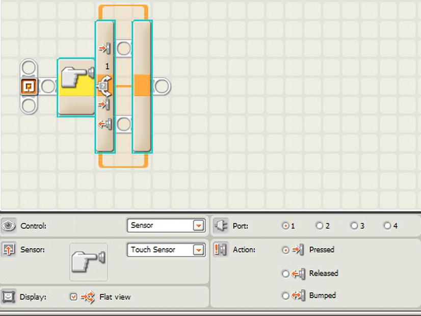
Figure 6-1. Default Switch block settings
You can see that the Switch block contains a pair of sequence beams; one beam is followed if the condition is “true” and the other beam is followed if the condition is evaluated as “false.” You can add program blocks on these beams, and they will be run based on the state of the Switch block.
Note A Switch block is a simple State machine. A State machine is a device that stores the status of a value and can run an event based on a change to that value. Some State machines are simple and have only values of True or False, while others can have a larger set of possible values.
A basic example of the Switch block would be a program that plays a tone and displays a smiley face on the NXT when the Touch sensor on port 1 is pressed. To start, move a Switch block to the sequence beam, as seen in Figure 6-2.

Figure 6-2. Switch block added to sequence beam
You will notice that the default settings for the Switch block are already configured for a Touch sensor on port 1. The upper sequence beam in the Switch block will run when the Touch sensor is pressed (or True) and the lower sequence beam will run when the Switch block is in its default state of being unpressed (or False). If True, you want to play a tone and display a smiley face, so add a Sound block and a Display block to the upper sequence beam. On the lower sequence beam, simply add a Display block to clear the display when the button is not pressed. Include this logic inside a forever loop so the condition of the Touch sensor can be checked repeatedly (see Figure 6-3). These are also referred to as “switch loops,” and are used throughout programs to help control program flow.

Figure 6-3. Loop block surrounding Switch block logic
Is the Touch sensor pressed? Yes or no? This is the logic being presented to the Switch block. If you were drawing a flow diagram, it would look something like Figure 6-4.
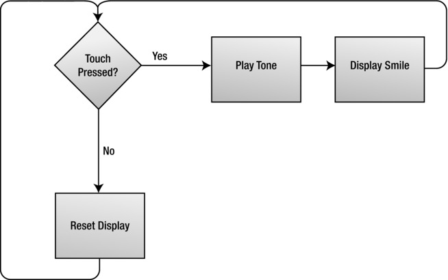
Figure 6-4. Flow chart showing logic used by the sample Switch block program
The previous example showed how to deal with simple on or off (pressed or not pressed) states, but you can also evaluate numeric values or ranges. For example, you can test whether a value is greater than or less than a given input value.
In Figure 6-5, you can see a program that is evaluating a raw numeric value coming in from a Light sensor and playing one of two different sound tones based whether the value is higher or lower than 50.
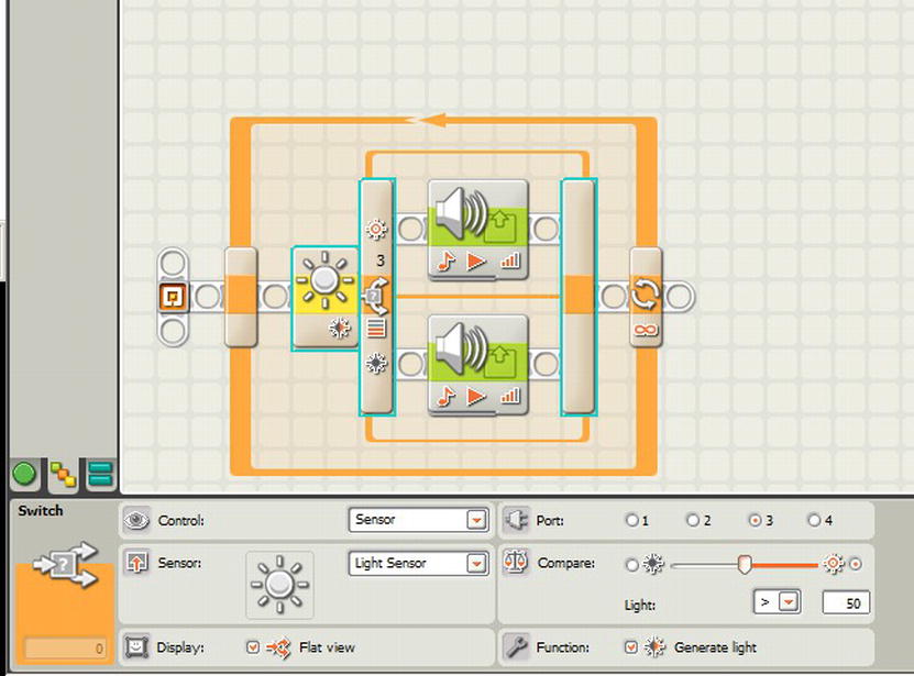
Figure 6-5. NXT-G program showing the evaluation of a Light sensor value
A simple Yes/No switch is easy to follow, but many times the decisions are a bit more complicated and require more than two options. On the Switch block, there is a property called Display. The default “Flat view” value is checked. If you uncheck this property, the Switch block will change and you will no longer see the pair of sequence bars but instead a series of tabs across the top of the block, as seen in Figure 6-6.

Figure 6-6. Tabbed view Switch block with Flat view unchecked
Now since the Touch sensor only has two states, pressed or not pressed, there are only two tabs. If you use the same sample program described earlier, and uncheck the Display property, you will notice as you click between the two tables that the blocks on the sequence bar will toggle between the values that were set up when Flat view was enabled. Figures 6-7 and 6-8 show this.

Figure 6-7. Logic on the True beam
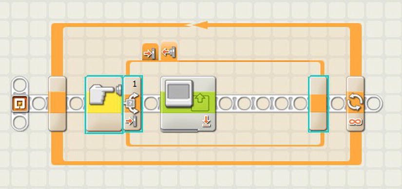
Figure 6-8. Logic on the False beam
Sometimes you may need to evaluate more than just two values, and this is why the tabs come in handy. Say for example you wanted to read the intensity value from a Color sensor and play different tones based on each color read by the sensor. If you simply set the Switch block to use a Color sensor, you’ll see that you only get the two options, True or False, based on the color range (see Figure 6-9).
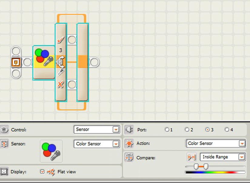
Figure 6-9. Switch block set to evaluate Color sensor
Note The LEGO MINDSTORMS Color sensor ships with the retail version of the MINDSTORMS kit, but are available for individual purchase as well. Currently, the LEGO Color sensor is allowed for use in FLL events. Check with your event rules to see if the Color sensor is allowed.
But what if you want to play a different tone for each color? You will have to change the Switch block to Control from “Sensor” to “Value”. You’ll notice that in the Properties panel, there is now a list of Conditions. For each condition in the list, a new tab will be added to the Switch block.
The Color sensor has six number values that are associated with detected colors:
- 1 = Black
- 2 = Blue
- 3 = Green
- 4 = Yellow
- 5 = Red
- 6 = White
So you will need to add six conditions to the list to create a tab for each of the detectable colors. To add items to the Conditions list, simply select the Plus button next to the list (see Figure 6-10).
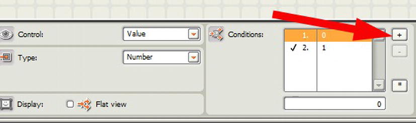
Figure 6-10. Adding items to the Conditions list
In the list, the column on the left contains the condition numbers, and the column on the right contains the value that it will be comparing. So for the Color sensor values, you will need to add the values as ranging from 1 to 6. You can leave a zero value for the default in case no color is detected. In Figure 6-11, you can see that there are seven total conditions in the list: values 1 to 6 are color values and 0 is the default condition.

Figure 6-11. Conditions added and tabs increased
Note To set a value in the Conditions list as the default condition, simply highlight it in the list and select the Asterisk button. A check mark will appear in the left column next to the condition. The default condition will be the tab that is followed in the Switch block when none of the other conditions are met.
Note By default, the size of the Switch block may be too small to show all seven tabs. Selecting the sequence bar inside the Switch block and dragging to the right will expand the size of the Switch block, allowing you to see all the tabs.
Now that the conditions are configured on the Switch block, an input value needs to be connected via a data wire. Add a Color sensor block and run a data wire from the Detected Color Data Plug to the Value Data Plug on the Switch block. It should look like Figure 6-12 when set up.

Figure 6-12. Color sensor block wired to Switch block
The next step will be to add some logic to the tabs. Since we want to play different tones based on the color detected, a Sound block should be added to each of the tabs, except the 0 tab since you would not want to play a sound when no color is detected. The tabs should now look like Figure 6-13.

Figure 6-13. Sound block added to the Conditions tab
Be sure to add and set a Sound block on each tab. As you click between the different tabs, you will notice that the sequence bar updates according to the logic associated with that tab.
Note When working a large number of tabs, you will find that the room for error increases because it’s easy to forget about a value or logic hidden on one of the tabs.
For this program to work, it will need to be wrapped in a Loop block so that the Switch block can continue to evaluate the Color sensor block value over and over again; otherwise, it will evaluate the sensor value once, and then end the program (see Figure 6-14).
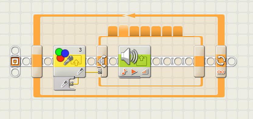
Figure 6-14. Loop block wrapped around the Color sensor logic
If you want to make the program a little more interesting, you could add a display within each tab as well. You could have it play a tone and also display the color’s name. So the color red would play an “A” note and display the word “RED” on the NXT screen (see Figure 6-15).

Figure 6-15. Adding a Display block to show the name of the color detected
ROBOT HAVING TO THINK FOR ITSELF
Once during a FLL Body Forward game, there was a series of five panels that represented bad and good cells. The panels had black on one side and white on the other. The idea was that you needed to flip black panels to white, but the panels were reset to a random pattern for each match, so there was no way to pre-program a robot to adjust the panels correctly. The robot’s program had to be smart enough to evaluate each panel and decide if it needed to be flipped or not.
This was a mission with a big point task, but since it required the use of some conditional logic, many teams ignored the task and left the high-point mission alone. With a simple understanding of Switch blocks, a robot’s program could make decisions based on its environment and get some easy points.
With the Switch block Control property set to Value, you can now evaluate multiple value types from various sources. This gives the Switch block a lot of power when it comes to making choices that affect how your robot will respond to different situations.
Combining the Variable block with the Switch block can become a very powerful tool when you want your robot to think for itself. Say your robot is performing a mission that requires it to change its speed as it approaches a series of parallel black stripes on the game surface. As the number of stripes you pass increases, the speed of the robot needs to slow down and then come to a complete stop once it reaches stripe number 4. But if you don’t know what the exact distance is, or maybe it changes every time, you will need a program that can keep track of the number of stripes you have passed and vary the robot’s speed based on that value.
So by using a Light sensor, a variable to store the counted lines, and a Switch block, you can allow your robot to determine on its own where and when it needs to adjust its speed.
First, create a variable called LineCount with a data type of Number (see Figure 6-16).

Figure 6-16. LineCount variable created
On the sequence beam, set the initial value of the LineCount variable by writing a 0 to the variable with a Variable block, as in Figure 6-17.
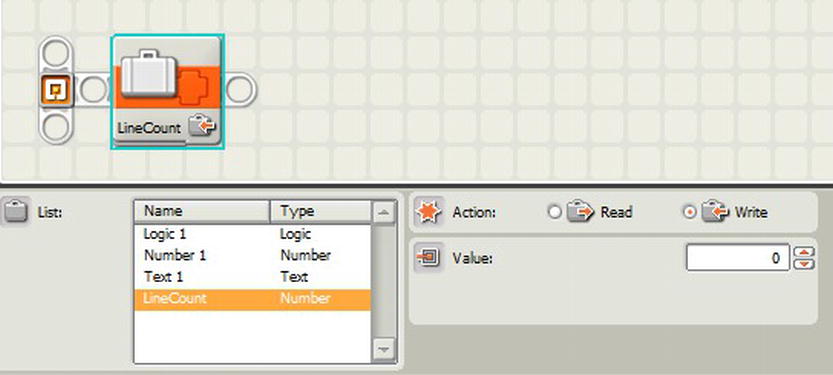
Figure 6-17. Initializing the LineCount variable
Then you will add a Move block to start the robot in motion. Follow this with a Loop block that contains a Wait block set for the Light sensor. Your current code should contain what you see in Figure 6-18.
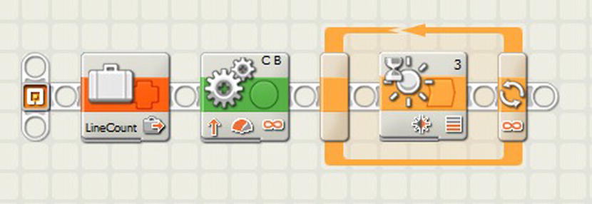
Figure 6-18. Sample code with the Loop block and Light sensor
After the Wait block, you want to increment the LineCount variable by a value of 1. The exiting of the Wait tells you that a black line was seen and that you need to increase the line count to account for the line. In Figure 6-19, you can see that a Variable block value is passed into the Math block, where 1 is added to the current value and then resaved into the Variable block preceding the Math block.
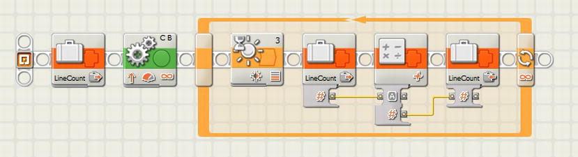
Figure 6-19. Incrementing of the LineCount variable
Before the code looks for another black line, the LineCount variable is evaluated by a Switch block. The Switch block is looking for the number of lines that have been detected. The tabs are set to follow the following values:
| Line Count | Motor Power |
| 1 | 90 |
| 2 | 50 |
| 3 | 30 |
| 4 | stop |
Each tab will contain a Variable block that writes the power value associated with the LineCount condition to a variable called MotorPwr. In Figure 6-20, you can see the tab configuration when the LineCount is equal to three.
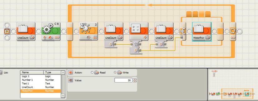
Figure 6-20. Switch block setting MotorPwr to 30
At the end of the Switch block, there would be a Move block with the MotorPwr value being passed in as the current value for the robot’s motor power (see Figure 6-21).

Figure 6-21. MotorPwr value being assigned to the power property of the Move block
The Loop block could be set to break out of the loop after the fourth black line is detected as well, so that the LineCount variable will serve two purposes (see Figure 6-22).
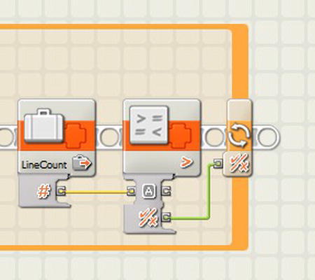
Figure 6-22. Using LineCount to break out of the Loop block
If you have thick black lines, you will have to add some extra logic to the code so that you can detect the starting edge of the black line and the ending edge of the black line. The logic would be as follows:
- Move Unlimited.
- Wait for Black.
- Move Unlimited.
- Wait for White.
This approach would work well inside a MyBlock that you create to handle black and white edge detection.
Sometimes there is the need to make decisions inside decisions. To do this, you can insert a Switch block inside other Switch blocks; this is called nesting. The sequence beam inside the Switch block acts just the same as the normal sequence beam—so anything you can do on one, you can do on the other. Figure 6-23 shows multiple Switch blocks nested together.
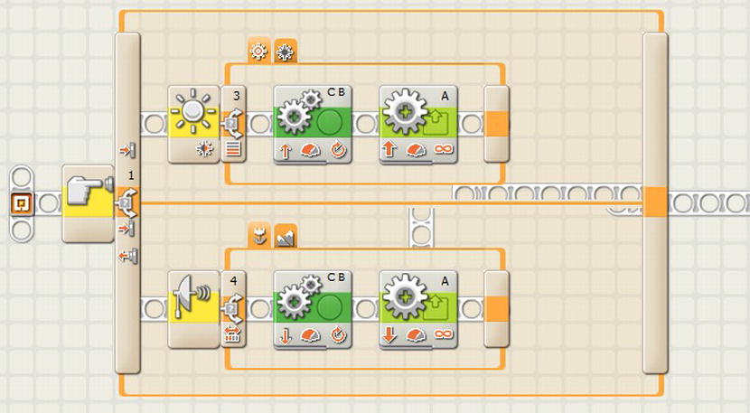
Figure 6-23. Nested Switch blocks
You will notice that multiple Switch blocks can get very confusing to read, and it is tough to follow the program flow. The situation in Figure 6-23 is a good example of when a MyBlock can help with the readability of a program.
One of the more overlooked blocks in NXT-G is the Logic block. This block allows you to compare two logic values (True/False or Yes/No) in various configurations. The Switch block does a simple comparison of a single condition. The Logic block allows you to make multiple comparisons. For example, the Switch block can answer a question such as “Is the Touch sensor on port 1 pressed?,” but if you wanted to answer a more complex question such as “Are both Touch sensors on ports 1 and 2 pressed?,” you’d need to use a Logic block to make this comparison.
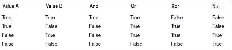
The Logic block has four Operation values:
- Or: If either one of the values is True, then this operation will return a True. Only if both values are False will this operation return a False.
- And: If both values are True, then a True is returned. If any of the values are False, then a False is returned.
- Xor (Exclusive Or): Works similar to the Or, but requires both values to be unique in order for a True to be returned.
- Not: Only checks the Value A being passed to the block, and returns the opposite. So a True returns a False, and a False returns a True.
The Logic block allows for two logical data type values. These can either be input via data wires or set in the Properties panel for the block.
Table 6-1 gives a complete breakdown of how the different operations work based on the input values.
Table 6-1. Logic Block Value Comparison Table
A good program example would be, let’s say, if your robot has two Touch sensors mounted on its rear bumper and you want to know when the robot has squared up to a wall on the game table. If you only check one sensor, your robot might not be completely squared. But you know that when both sensors are pressed, the robot is completely perpendicular to the wall—and you’re ready to move on to the next step in your mission.
The program for this would be very hard and messy to write if you didn’t have a Logic block—you’d have to have a series of nested Switch blocks, as seen in Figure 6-24. But if you use the Logic block, the code will be much cleaner, as seen in Figure 6-25.
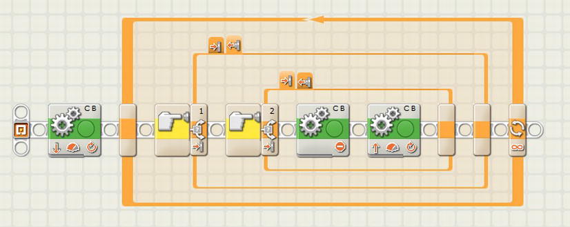
Figure 6-24. Nested Switch blocks detecting two Touch sensors pressed
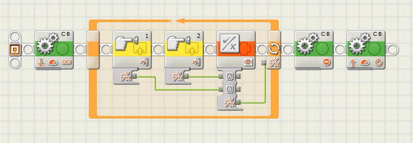
Figure 6-25. Logic block simplifying the detection of two Touch sensors pressed
The code logic in Figure 6-25 is easy to read: the robot moves backward toward the wall. Once both Touch sensors are pressed, the program will exit the loop, and then the robot will stop and then move forward.
The Compare block is used to compare two number values. It outputs True or False depending on the condition chosen in the Options panel. For example, you could compare the output from the Ultrasonic sensor to a minimum distance you wish to maintain between the robot and the wall.
The Compare block has three Operation values:
- Greater Than (>): If the Input A value is greater than Input B, the Compare block will return True; otherwise, the value of False will be returned.
- Less Than (<): If the Input A value is less than Input B, the Compare block will return True; otherwise, the value of False will be returned.
- Equal (=): If Input A is the same as Input B, the value of True will be returned.
Figure 6-26 shows a sample program that uses the Compare block with an Ultrasonic sensor to cause the robot to reverse when it gets too close to a wall.
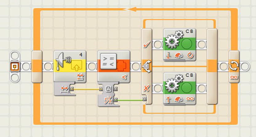
Figure 6-26. A Compare block sample program that will reverse the robot when it approaches a wall
There are alternatives to the Compare block. Many of the other blocks, including the Loop block, Switch block, and the Wait blocks have the same compare functionality included inside of them already. The example shown in Figure 6-26 could have been written using the Ultrasonic sensor compare function built into the Switch block, as seen in Figure 6-27.
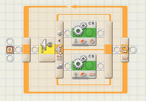
Figure 6-27. A Switch block using an Ultrasonic sensor sample program that will reverse the robot when it approaches a wall
The Range block will evaluate a number value and check if it falls inside or outside a given range of numbers. The range values can be hard-coded or wired into the block. Most of the time, the range values are preset in your program while the test value is input via a data wire from another block or variable.
The Operations property of the Range block gives you the following options:
- Inside Range: If the test value is between Value A and Value B, or is equal to either of the values, then the block will return a value of True. This is called an inclusive comparison.
- Outside Range: If the test value is outside the range of Value A and Value B, and does not equal either of the values, then a value of True will be returned. This is called an exclusive comparison.
The example in Figure 6-28 shows the Range block used to see if a Light sensor block has found a gray line. Such a line would have a light range between 1 and 100, so the range values on the Range block are set to 45 through 65, and the Operation property is set to “inside range”. If True, the program will play a simple tone with the Sound block.

Figure 6-28. A Range block looking for gray lines plays a tone when found within the range
The Range block can come in handy when conditional decisions are not as simple as “Is the value greater than 50?” but are more like “Is the value greater than 80 but less than 30?”. Being able to test a range of values comes in very handy in dealing with light intensities. This is demonstrated in more detail in the chapter on light values.
Summary
Mastering the use of these conditional blocks will allow our robot to make smart choices when it’s on the game field, giving it the ability to adapt to changes and overcome any unknowns it may run into. Testing and experimenting with the different conditional blocks will give you a better understanding of how each of them can add better decision making to your programs. The ability to display a good understanding of such blocks to a technical judge at an event can help you and your team stand out from teams that are using hard-coded logic in their code.